ANTES DE INICIAR
Lea estas instrucciones completa
y cuidadosamente.
•IMPORTANTE —Guarde estas
instrucciones para uso del inspector local.
•IMPORTANTE —Observe todos
los códigos y órdenes de ley.
• Nota al instalador – Asegúrese de dejar estas
instrucciones con el consumidor.
• Nota al consumidor – Conserve estas
instrucciones para referencia futura.
• Nivel de destreza – La instalación de este
aparato requiere habilidades mecánicas
y eléctricas básicas.
• Tiempo de ejecución – 1 hora
•La instalación adecuada es responsabilidad
del instalador.
•La garantía no cubre fallas producidas
por la instalación inadecuada del producto.
Consulte el Manual del propietario para
obtener información sobre la garantía.
IMPORTANTE:
• Use este horno únicamente para los fines para
los que está destinado.
• Nunca use el horno como calefacción o para
calentar una habitación. El uso prolongado
del horno sin la ventilación adecuada puede
ser peligroso.
¿Preguntas? Llame al 800.GE.CARES (800.432.2737) o bien visite nuestra página Web: GEAppliances.com
Instrucciones
de instalación
Profile Advantium
™
120 Hornos
empotrados SpeedCook
PSB1000 PSB1001
PRECAUCIÓN:
Para su seguridad personal, retire el fusible
doméstico o el disyuntor antes de comenzar la
instalación, para evitar lesiones severas o fatales.
PRECAUCIÓN:
Para su seguridad personal, la superficie de
montaje debe poder sostener la carga del gabinete,
además del peso adicional de las 75 libras del
producto, más las cargas adicionales del horno
de hasta 50 libras o un peso total de 125 libras.
PRECAUCIÓN:
Para su seguridad personal, este producto no puede
ser instalado en arreglos de alacena, como por
ejemplo, islas, penínsulas o debajo de superficies
de trabajo.
ÍNDICE
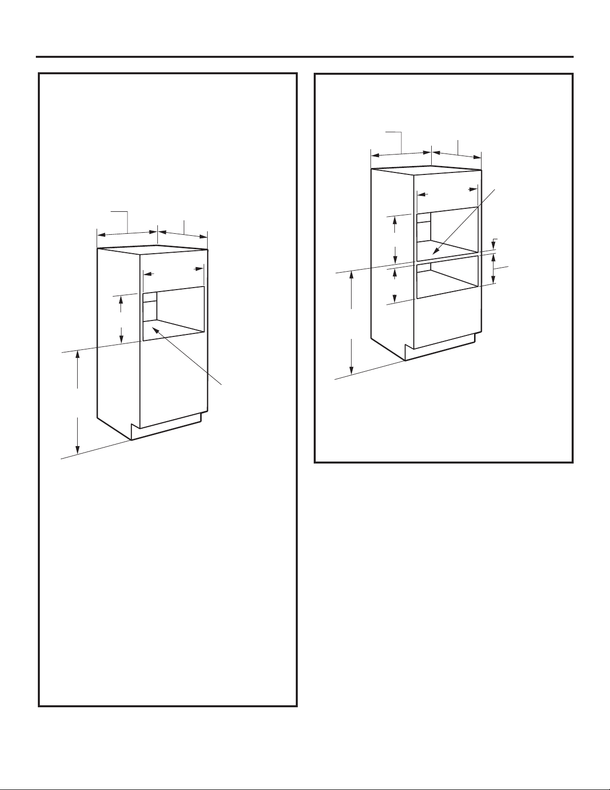
Información sobre el diseño
Modelos disponibles ............................................................ 2
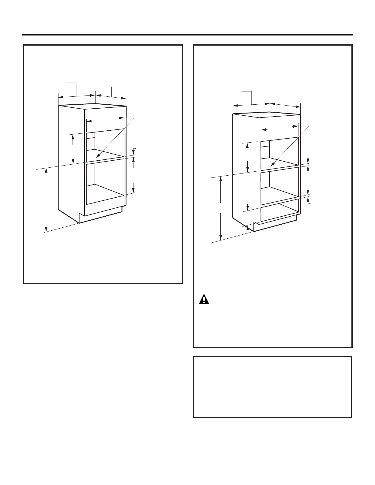
Dimensiones del producto y espacio libre ................ 2
Herramientas necesarias .................................................. 2
Partes incluidas ...................................................................... 2
Planificación anticipada .................................................... 3
Preparación para la instalación
Requisitos eléctricos ............................................................ 4
Prepare la abertura.......................................................... 5, 6
Retire el embalaje.................................................................. 6
Instalación
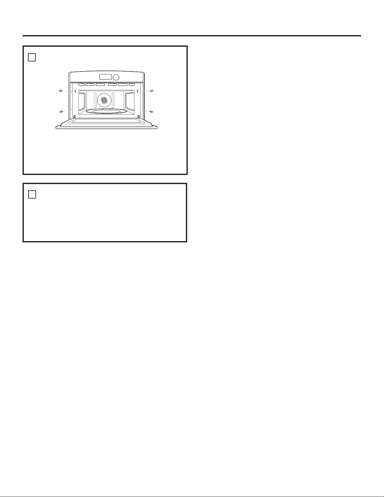
Paso 1, deslice el horno dentro del corte .................. 7
Paso 2, instale el recorte inferior.................................... 7
Paso 3, instale los tornillos de montaje ...................... 8
Paso 4, finalice la instalación .......................................... 8
MFL59060902 49-40607 02-09 JR