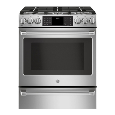
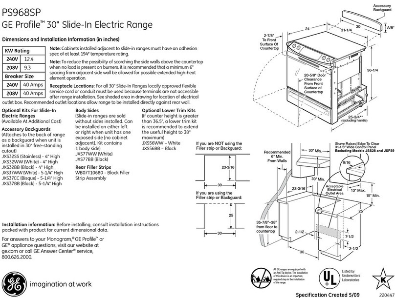
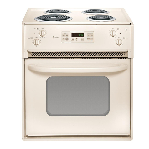
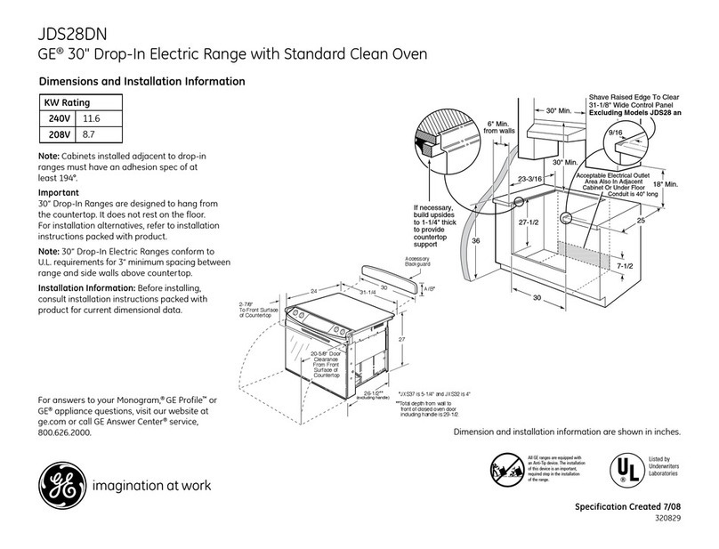
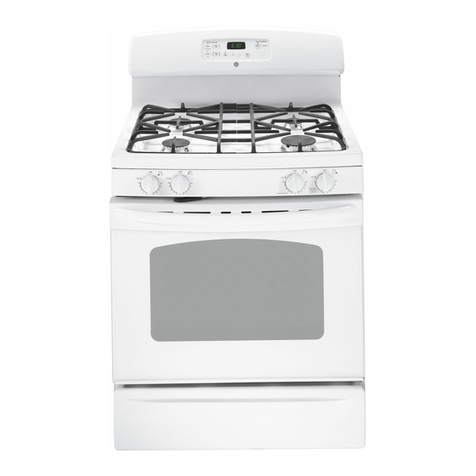
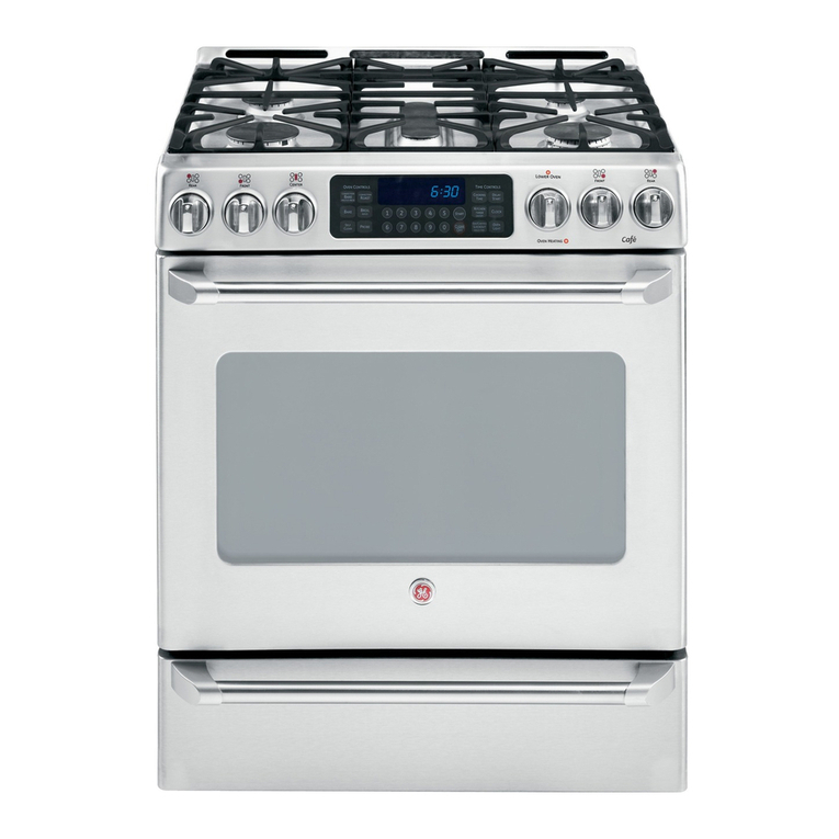
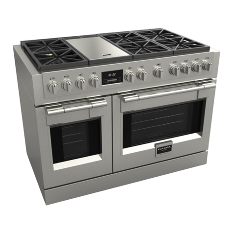
GE PHS925ST1SS How to use

GE Appliances
General Electric Company
Louisville, Kentucky 40225
31-9219
PHS925ST1SS
PS978ST1SS
Technical Service Guide
December 2011
GE Appliances
Profile 30-in.
Slide-in Induction
and Radiant Ranges

– 2 –
IMPORTANT SAFETY NOTICE
The information in this service guide is intended for use by
individuals possessing adequate backgrounds of electrical,
electronic, and mechanical experience. Any attempt to repair a
major appliance may result in personal injury and property
damage. The manufacturer or seller cannot be responsible for the
interpretation of this information, nor can it assume any liability in
connection with its use.
WARNING
To avoid personal injury, disconnect power before servicing
this product. If electrical power is required for diagnosis or test
purposes, disconnect the power immediately after performing the
necessary checks.
RECONNECT ALL GROUNDING DEVICES
If grounding wires, screws, straps, clips, nuts, or washers used to
complete a path to ground are removed for service, they must be
returned to their original position and properly fastened.
!
GE Appliances
Technical Service Guide
Copyright © 2011
All rights reserved. This service guide may not be reproduced in whole or in part
in any form without written permission from the General Electric Company.

– 3 –
Table of Contents
Aluminum Plate ................................................................................................................................................................66
Bake Element......................................................................................................................................................................48
Bake Thermal Switch ......................................................................................................................................................65
Blower Assembly ..............................................................................................................................................................64
Bridge Board ......................................................................................................................................................................66
Broil Element.......................................................................................................................................................................44
Circuit Boards Connector Locator Views...............................................................................................................16
Clean Thermal Switch.....................................................................................................................................................65
Component Locator Views........................................................................................................................................... 7
Control Panel .....................................................................................................................................................................29
Convection Element.........................................................................................................................................................46
Convection Fan Assembly............................................................................................................................................47
Convection Fan Cover ....................................................................................................................................................46
Cooktop Assembly ..........................................................................................................................................................30
Cooktop Components - PS978 ..................................................................................................................................73
Cooktop Components - PSH925 ...............................................................................................................................66
Cooktop Elements ............................................................................................................................................................67
Cooling Fan and FAD (Fan Apparency Device)....................................................................................................62
Daughter Relay Module (DRM) ..................................................................................................................................42
Diagnostics and Service Information......................................................................................................................75
Door Lock Assembly .......................................................................................................................................................56
Door Switch ........................................................................................................................................................................56
Filter Board ..........................................................................................................................................................................72
Generator Boards.............................................................................................................................................................71
Glass Touch Panel ...........................................................................................................................................................30
High Limit Thermostat ...................................................................................................................................................62
Hot Surface Indicator Light Assembly....................................................................................................................74
Induction Module .............................................................................................................................................................70
Introduction......................................................................................................................................................................... 4
Left Side Panel ...................................................................................................................................................................33
LINbus Connectors...........................................................................................................................................................69
Main Logic Board .............................................................................................................................................................29
Meat Probe and Outlet ..................................................................................................................................................51
Nomenclature .................................................................................................................................................................... 6
Oven Components ..........................................................................................................................................................41
Oven Door Assembly ......................................................................................................................................................21
Oven Door Hinge Receiver ...........................................................................................................................................40
Oven Light Assembly ......................................................................................................................................................54
Oven Temperature Sensor............................................................................................................................................44
Radiant Heating Elements............................................................................................................................................73
Range Components.........................................................................................................................................................21
Rear Cover .........................................................................................................................................................................32
Relay Power Supply Module (RPSM) .......................................................................................................................41
Right Side Panel ................................................................................................................................................................37
Schematics and Wiring Diagrams............................................................................................................................82
Smoke Eliminator/Vent Tube.......................................................................................................................................52
Thermal Cut Out................................................................................................................................................................70
Thermal Cut Out (TCO) Switch.....................................................................................................................................64
Upper Oven Liner .............................................................................................................................................................60
Warming Drawer Assembly .......................................................................................................................................28
Warming Drawer Element............................................................................................................................................63
Warranty ..............................................................................................................................................................................86
– 4 –
Introduction
The Profile 30-in. Slide-In Induction Range with convection oven and warming drawer features electronic
oven and induction element controls. The induction elements provide unmatched cooking performance and
flexibility. Induction technology heats only the pan and its contents and offers energy efficiency by reducing
wasted heat when compared to radiant and gas cooktops.
The Profile 30-in. Slide-in Induction Range has the following new features:
• Innovative technology―delivers the responsiveness of a gas cooktop.
• Superior performance―induction technology heats only the pan and
its contents, providing an incredibly fast boil time.
• Remarkable versatility―this induction cooktop offers the choice of
19 different power levels, including a 3700-watt, 11" element for large
cookware , warming capability, and a low-heat simmer setting for
delicate sauces.
• Cooler cooktop surface―since there is not a traditional thermal
heating element, the induction cooktop stays cooler than conventional
radiant cooktops.
• Below cooktop venting―dissipates heat, permitting less depth to the
burner box.
• Easy cleanability―cooktop cleaning is easier since spills and splatters do not burn on the cooktop.
• Electronically controlled oven heating
elements―provide precise cooking control with
fast preheating.
• Convection mode uses reverse-air convection
technology―a bidirectional fan that works with
a dedicated third heating element to promote
even heat circulation.
• Performance compensation for 208-volt
installation―boosts power as needed in
multifamily dwellings.
• Cooktop locked out during self clean
• Hidden oven bake element―concealed
beneath the oven floor, allows quick and easy
ash removal following the self-clean cycle.
• Two nickel-plated sliding extension racks
Model PHS925
(Continued next page)

– 5 –
GE's Profile 30-in. Slide-In Radiant Range utilizes 2 ovens with convection cooking in the lower oven. This
range features electronic oven and surface unit controls that combine modern digital technology with ease
of operation. The superior style and performance parallel many commercial ranges.
The Profile 30-in. Slide-in Radiant Range has the following new features:
• Electronically controlled oven heating elements―provide precise cooking control with fast preheating.
• Convection mode uses reverse-air convection technology―a bidirectional fan that works with a
dedicated third heating element to
promote even heat circulation.
• Performance compensation for 208-
volt installation―boosts power as
needed in multifamily dwellings.
• 6.6 cu. ft. total capacity
• Cooktop locked out during self-clean
• New motorized self-clean door latch
• Recessed convection, low-profile broil
elements, and hidden upper and lower
oven bake elements
• Full-extension racks
Model PS785

– 6 –
Brand
P = Profile
P H S 9 2 5 S T 1 S S
Nomenclature
Model Number
Feature Pack
Designates features–the higher
the number, the more features
Product Color
SS = Stainless Steel
Indicator for Engineering
and Product Service Only
Model Year Designator
Model/Door Color
S = Stainless
Configuration
H = Induction
30" Slide-In
Nomenclature
Mini-Manual
The nomenclature plate is located behind
the warming drawer panel on PHS925, and
behind the lower oven door on PS978.
The mini-manual is taped to the left rear
corner of the left body side panel.
Serial Number
The first two characters of the serial number
identify the month and year of manufacture.
Example: ZV123456S = December, 2011
Z - DEC
A - JAN
D - FEB
F - MAR
G - APR
H - MAY
L - JUN
M - JUL
R - AUG
S - SEP
T - OCT
V - NOV
2011 - V
2010 - T
2009 - S
2008 - R
2007 - M
2006 - L
2005 - H
2004 - G
2003 - F
2002 - D
2001 - A
2000 - Z
The letter designating
the year repeats every
12 years.
Example:
V - 2011
V - 1999
V - 1987

– 7 –
Component Locator Views
(Continued next page)
Front View - PHS925
Front View - PS978
Induction Cooktop
Control Panel
Control Panel
Radiant Cooktop
Oven
Warming Drawer
Upper Oven
Lower Oven

– 8 –
Oven and Warming Drawer - Front View - PHS925
Shown with oven door and warming drawer removed
(Continued next page)
Hidden Bake Element
Broil Element
Meat Probe Outlet
Light
Oven Temperature Sensor
Door Lock
Door Switch
Convection Fan and Element
Warming Drawer Element

– 9 –
Upper and Lower Oven - Front View - PS978
Hidden Bake Element
Broil Element
Meat Probe Outlet
Light
Door Lock
Door Switch
Light
Door Lock
Hidden Bake Element
Broil Element
Door Switch
Smoke Eliminator
Light
Oven Temperature Sensor
Convection Fan and Element
Shown with oven doors removed
(Continued next page)

– 10 – (Continued next page)
Main Top - PHS925
Control Panel - PHS925
Display Board
Display Board Main Logic Board
Fan Apparency Device (FAD)
Hot Surface Indicator Light Assembly
Cooling Fan
Induction Module
Hi Limit Thermostat

– 11 –
Main Top - PS978
Control Panel - PS978
Display Board
Display Board
Clean Thermal Switch
Bake Thermal Switch
(Continued next page)
Main Logic Board

– 12 –
Cooktop Induction Elements - PHS925
Warming Element Induction Element
Induction Element
Induction Element
Induction Element
Left Generator Board Right Generator Board
Induction Module - PHS925
(Continued next page)
Bridge Board
Filter Board
Cooling Fan

– 13 –
Cooktop Radiant Elements - PS978
Warming Zone Element
Hot Surface Indicator Light Assembly
Right Rear Element
Left Front Element
Left Rear Element
Dual 5 & 8 Inch
240 Volt
1100 Watts
2400 Watts
"Power Boil"
12-Inch Tri-Ring
240 Volt
3000 Watts
6" - 1050 Watts
9" - 900 Watts
12" - 1050 Watts
8 Inch
240 Volt
2000 Watts Warming
240 Volt
120 Watts
6 Inch
240 Volt
1500 Watts
Tri-Ring Element
(Continued next page)

– 14 –
Rear View - PHS925
Note: The oven bake element terminals are located behind the left side panel.
Convection Fan Motor
Oven Temperature Sensor
Convection Element
Broil Element
Warming Drawer Element
Convection Fan
Motor Capacitor
Daughter Relay Module (DRM)
(RPSM) Relay
Power Supply
Module
(Continued next page)

– 15 –
Rear View - PS978
Oven Vent Tube
Upper Oven Door
Lock Assembly
Lower Oven Door
Lock Assembly
TCO
Convection Element
Convection
Fan Motor
Convection Fan
Motor Capacitor
Upper Oven
Broil Element
Lower Oven
Broil Element
Daughter Relay
Module 2 (DRM 2)
RPSM (Relay Power
Supply Module) Main
Board
Daughter Relay Module 1 (DRM 1)
Lower Oven Temperature Sensor
RPSM (Relay Power
Supply Module) AUX
Board
Upper Oven
Temperature
Sensor
Note: The upper and lower oven bake element terminals are located behind the left side panel.

– 16 –
Circuit Boards Connector Locator Views
Relay Power Supply Module - PHS925
J21
J7
J16
J17
(Continued next page)
J7 - Door Lock Motor, Cooling Fan, Jumper
Wire K8 to K1, Warming Drawer Element,
Neutral, Oven Light, Convection Fan Motor
Direction
J10 - Ground
J11 - Neutral Standby
J14 - L1
J15 - RPSM to DRM Communication
J16 - Oven Lock Switch, Oven Unlock Switch, FAD
J17 - Communication Cable (LINbus)
J20 - 240 VAC
J21 - Bad Line Monitor
K1 - Convection Fan Motor Direction
K3 - Broil/Bake Element Selector Relay
K4 - Oven Light
K5 - Cooling Fan
K7 - Bake/Convection Element Selector Relay
K8 - Convection Fan Motor
K10 - Convection Element Relay
K11 - Warming Drawer Element
K13 - Door Lock Motor
K14 - Double Line Break Relay
K1
K4
K5
K8
K11
K13
K3
K7
K10
K14
J10
J20
J14
J11
J15

– 17 –
Daughter Relay Module - PHS925
J15 - RPSM to DRM Communication
J23 and J24 - Warming Zone Connections
K17 - Warming Zone
J23
J24
K17
J15
Main Logic Board - PHS925 and PS978
J821
J501 J241
J851
J841
J201 - Model Selector
J241 - LINbus
J501 - Oven Sensor, Meat Probe (PHS925), Upper Oven Sensor (PS978)
J502 - Lower Oven Temperature Sensor, Meat Probe (PS978)
J851 - Oven Touch Panel Board
J821 - Left Side Touch Panel Board
J841 - Right Side Touch Panel Board
J201
J502
(Continued next page)

– 18 – (Continued next page)
Relay Power Supply Module MAIN - PS978
J7 - Blower, Convection Fan, Door Lock Motor
J10 - Cabinet Ground
J11 - Neutral
J14 - L1
J15 - Communications
J16 - Lock Switches
J17 - Communications
J20 - L1 and L2
J21 - Neutral
K1 - Convection Fan Motor Direction
K3 - Lower Broil, Lower Bake, and Convection
K4 - Both Oven Lights
K5 - Blower
K7 - Lower Bake and Convection Elements
K8 - Convection Fan Motor Power
K10 - Convection Element
K11 - Not Used
K13 - Upper Door Lock Motor
K14 - Double Line Break for Lower Bake,
(Upper), Oven Lights, Door Switches
Elements
Lower Broil, Convection, and Lower Broil
Boost Elements.
J7
J14
J21
K1
K4
K5
K8
K11
K13
K3
K7
K10
K14
J10
J11 J16
J17 J15
J20
Relay Jumper Wire
Relay Jumper Wire

– 19 –
Relay Power Supply Module AUX - PS978
J7
K10
K14 J17
J15
J6
J5
J3
J2
K1
K4
K5
K8
K11
K13
K2
K6
J14
J2 - RF Inner Element
J3 - L1
J5 - LR Element
J6 - L1
J7 - RF Center, RF Outer, CR, LF Inner, and LF Outer
Elements
J14 - L1
J15 - Communications
J17 - Communications
K1 - LF Inner Element
K2 - RF Inner Element
K4 - LF Outer Element
K5 - CR Element
K6 - LR Element
K8 - RF Center Element
K10 - Double Line Break for RF Element
K11 - RR Element
K13 - RF Outer Element
K14 - Double Line Break for LF Element
Elements
(Continued next page)

– 20 –
Daughter Relay Module 1 - PS978
J23
J24
K12 J15
Daughter Relay Module 2 - PS978
J15 - Communications
K3 - Double Line Break - RR
K7 - Double Line Break - LR J15
K1
K7
K3
J6
K17
J6 - Convection Fan, L1, and Lower Door Lock Motor
J15 - Communications
J23 - L1
J24 - Convection Fan
K1 - Outer Broil (Lower)
K3 - Upper Bake and Upper Broil Elements
K7 - Double Line Break for Upper Bake, Upper Broil,
and Upper Broil Boost Elements
K12 - Lower Door Lock Motor
K17 - Outer Broil (Upper)
K18 - Upper Bake Element
and Upper Broil Boost Elements
K7
K3
Other manuals for PHS925ST1SS
2
This manual suits for next models
1
Table of contents
Other GE Range manuals