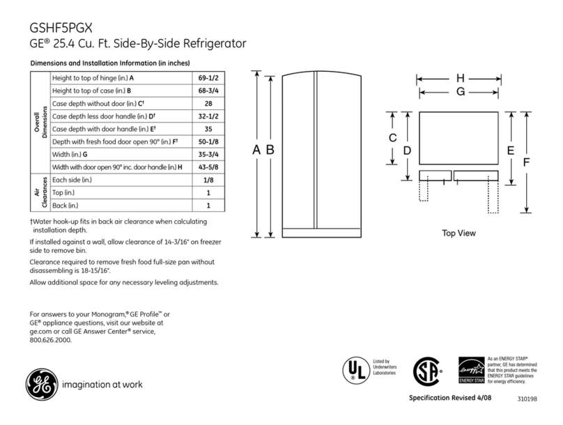
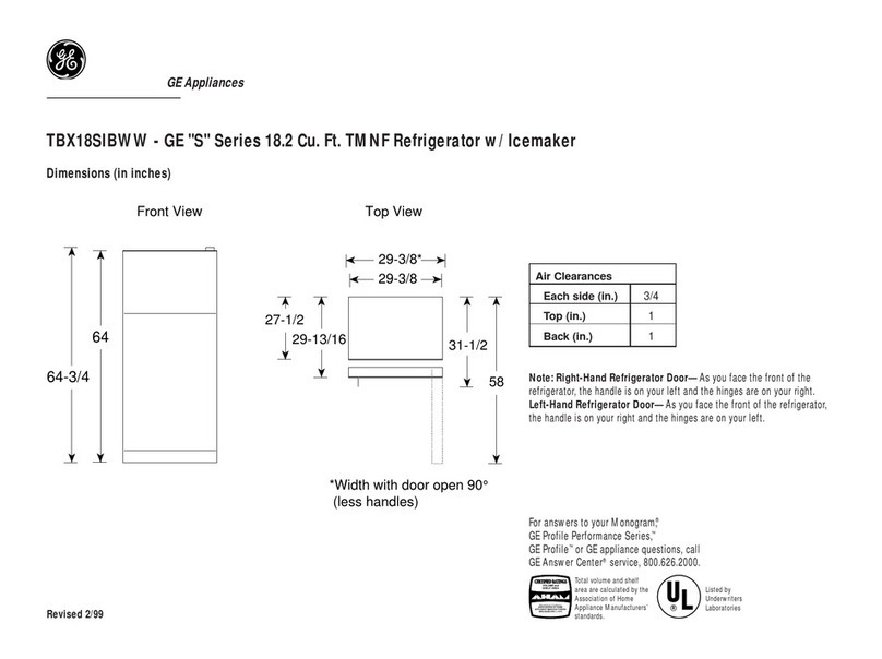
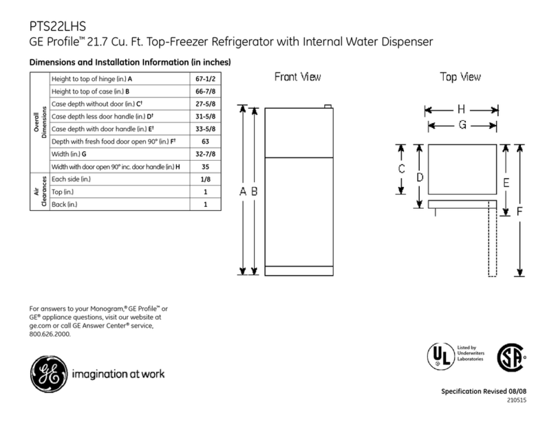
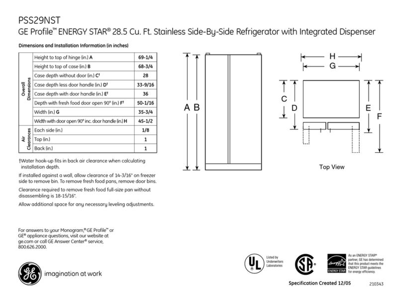
GE GBS22**P How to use

SEARS
3EPT.731A
TECHNICALFLASH
DISTRICTMANAGER
CENTRALMANAGER
BRANCH MANAGER
CALL CENTRE MANAGER
PARTS
MANAGER T.
F. 46-106
JUNE
2OO4
CLAUDE BABINEAU_ DEPARTMENT 73IA
DIVISION 46
SOURCE C978
ERVICEMANUA
DIVISION
46
G.E.
REFRIGERATORS
2OO3
ELBCTRONIC
BOTTOM-MOUNT

GE
Consumer
&lndustrial
TECHNICAL
SERVICE
GUIDE
2003
Electron
ic Bottom-Mount
Refrigerators
MODEL
SERIES:
GBS22_
_P
GBS20__P
PDS22__P
PDS2O P
-=:
PUB# 31-9112 1tM

IMPORTANTSAFETY NOTICE
The information
in this service
guide is intended
for use by
individuals
possessing
adequatebackgrounds
of electrical,
electronic,and mechanical
experience.Any attemptto repaira
majorappliancemay resultin personal
injuryand property
damage.
Themanufacturer
orsellercannot
be responsible
forthe
interpretation
ofthisinformation,
norcanit assume
anyliabilityin
connection
withib use.
WARNING
To
avoid
personal
injurydisconnect
polver
beforeseMcing
this
product.
lf elestrical
poweris required
for diagnosis
or test
purposes,
disconnectthe power
immediately
afterperforming
the
necessarychecks.
RECONNECTALL GROUNDINGDEVICES
lf grounding
wires,screws,
Sfraps,
clips,nuts,orwashersused
to completea pathto ground
areremoved
for service,they must
beretumed
totheiroriginal
position
and
prcperlyfastened.
GE Consumer& lndustial
TechnialServloeGuide
Copynght@2004
All rightsreserved.
Thisservice
gufule
maynotbe reproduced
inwholeor in
partin anyform withoutwrittenpermission
fiorntte GenenalElecfic Comparry.
-2-

Table
of Contents
-3-

Doors
Theswingdirectionofthefreshfood
door
and
the
freezer
doorcanbereversed
onallmodels
except
stainlesssteel.
Stainlesssteelmodelsmust
beordered
asleftor
right
doorswing.
Removal
and Replacement
FreshFoodDoor
1. Lifi
the
treshfoodcompartment
doorhandle
firmly
upwardandoffofthe2doormounting
screws.
2. Reversetheabove
procedure
toreinstiall.
Note:Thedoorhandlecanbe
installed
inconectly.
Make
surethecurvedsideofthe
handle
is
towardtheoutsideedgeofthedoor.
FreezerDoor
1. Install2 doormountingscrewsonthetreezer
compartment
door.
2. lnsertthedoorhandleontothedoormount
screwsand
pullthe
handlefirmlytothe
left.
Note:Thedoor
handlecanbeinstalled
inconectly.
Make
sure
thehandleiscurved
upward
andislockedin
place.
Aproperly
installed
handlewillbecenteredonthedoor.
-4-

Troubleshooting
Tips- HandleInstallation
Handletoohardb
instrlUHandletequircs
excesivetorceto
itlr;fg,l
Mormting bolts too tight- Remove
the handle.Loosenthe mounting bola
sltghtly sothat the handle will snapinto place
wheninstalled.
Defective normting bracket or
bolts. Remove
handle.Checkfor defective
mounting
bracketsor bols. If defective,replace.
Install
handle according to Installation Instructions.
Larcehandle/l{andle
rmkes
ratilingnoise
at
fficlnretrt
Loosenormtingbolts If the handleinstallsproperly (slides
on and
locks/snapsinto place)but isloose,removethe
handleand tighten the mounting bola. Use
a
lomm socket
andratchetor wrench.Do not usea
screwdriverasit will not provide enough torque
for proper tightening. Reinstall handle according
to InsrallationInstructionsincluded wi& the
handle.
Freezerhandle is installed
baclmtards. Removehandle.Checkfor correct mounting
brackets
on the handle.There isaright bracket
(R) andaleft bracket(L). The handle hasthe
word 'RIGHT" printed in the bracket cavity.
The
"R'bracket shouldbeinstalledin the bracket
cavitymarked "RIGI{T". The "L" bracket should
beinsr^lledon theoppositeside.Reinstallhandle
according to Installation Instructions.
FreshFoodhandle is mormtedupside
dorrn or incorrectly relative to the
curve ofthe FreshFood door.
Make certain that the arrow label on the handle
ispointing at the centerof the unit. Toveri$, the
handle should look straight from a distance (not
slantedto the side).
-5-

ELECTRICAL
SPECIFICATIONS
Temperature
Control
(Position
5)...............
........32
-
4"F
DetrostConhol...
60hrs
@
40
minswith
nodooropening
OvertemperatureThermostat.............
140-110"F
DefrostThermistor.. ..--..-....70'F
ElectricalRating:115V.
AC,
60H2.................1
- 5Amp.
Maximum
CunentLeakage..... ........0.5
mA
Maximum
GroundPath[email protected].
14Ohms
EnergyConsumption.......507
k\rVh/yrfor
20culft
models
EnergyConsumption.......520
kWh/yrfor
22cuftmodels
NOLOADPERFORITIANCE
Control
Position:5€
AndAmbient
of;.......... .....
90'F
Fresh
Food,
"F..... .---...32
- 42
FrozenFood,
"F..... .......
-5- 5
Percent
RunningTime........... .........
45- 65
REFRIGERANONSYSTETTI
Minimum
CompressorGapacityVacuum......
........
22in.
Minimum
EqualizedPressure
@ 70"F 38 PS|G
@ 90"F...... 49 PStc
Reftigerant-R- 134a.. 4.06o2-
Compressor................ 690BTU/hr
INSTALLANON
Clearance
must
be
provided
attop,sides
andrear
ofthe
refrigerator
for
aircirculation.
ATTOP...... .1 inch
ATSIDES.. 0.125
inch
AT REAR... 1 inch
Theevaporatorfanforcesairthrough
the
evaporator
intothefteezer
compartment.
Airfromtheevaporator
isalso
forcedthrough
the
electronicdamperto
thetop
ofthe
air
tunnel,
throughthefreshfoodcompartment,andretums
totheevaporator.
Thefresh
food
compartment
receives
chilled
air
throughanelectronicdamperatthebottom,rear
oftheftesh
foodcompartment.Thedamperis
controlledbythe
main
controlboard.When
open,
thedamperallows
chilled
air
ftomthefreezer
to
move
into
thefresh
foodcompartment.
Airretums
from
theftesh
foodcompartment
tothe
freezercompartment
viatwoventslocated
tothe
left
and
right
of
the
airtunnel.
r coLD
AtR
*= MIXEDAIR
r r r flfl REIURNTO
EVAPOMTOR
\1
.-&
\ FRESH
FOOD'
\. \
i-$
-
FREEZERt,
!>
AIRFLOW
-6-

ModelNumber
V-NOV
Z-DEC
L.
JUN
M.JUL 1999
-V
R.
AUG 1998
-
T
s-sEP 1997-S
T-OCT 1996-R
2O0O
-Z ExamPle:
Serial Number
Thefirst
twocharactersoftheserialnumber
identifythemonth
and
year
ofmanufacture.
Example: AG123456S
=
January2004
A. JAN 2005-H Theletter
D- FEB 2004
- G designatingthe
F- MAR 2003- F year
repeats
every
G
-ApR 2OO2
_D 1?years.
H
-
MAY 2OO1
-A
T- 1974
T
-1986
T
-1998
Thenomenclaftlre
plate
islocatedonthe
upperleftwall
of
the
fresh
food
connpartment.
1995
-
M
1994
- L
i{TERICIR'SHELIGS
H=UPGMDEGT SS
K=SPI!+ROOFG|.ASS
M= SPILIL'rPf{OOF/SUDEOUTGLASS
S =STAINIESS STEELDOORS
EITERbRCOLOR
WW=WHTTE/VI/HITE
Ss=
SrANLESS,SfAINLESS
CC
=BISOUE/BISOUE
BB=BLACKtsl-ACK
-7-

Hectronic Gontrol Panel
Thetenperaturecontrolsarepreset
inthe
factoryat37"F
fortherefrigerator
clmpartment
andOoF
forthefreezer
compartnenL
Allow24
hours
forthe
temperature
ta
stahilizet0the
pres
et
re
com
mend
edsetti
n
gs.
Thetemperature
controls
candisplaybothhe SEf
tenperatureaswellasthe
actual
temperature
inthe
refrigerator
and
freezer.
Theactual
tenperature
nayvary
slighflyfron
theSEfrcnperaturebased
0nusageandoperatingenvirlnment
C
h
a
ngingtheTempe
nta
re
To
changetheEflrpqaane,press and rclcasethc
WBMBoT fiOl0Bpad. Thc SEf[ghtwill come
on and the displaywill showthe settcmpcrature.
To drange the tcanperature,tap eithcr the
WAfrMBor C0lD8paduntjl thedesired
temperahJreisdisplayed.Rcfrigerator temperatures
c:n be a{usted bcmeen 34'F and 47'F and the
frcczcr temperahrres canbe adjusted betwccn
4"Fand +8'F.
Once the dcsircd temperaturc hasbeen set,
the tcrnpcrature displaywiil r€turn to the actual
refrigerator and freezer tcmpcratures after 5
seconds.Scveraladjr:stmens nraybe required.
Eachtimeyou adjrrst
controls,allow 24 hours for thc
rcfrigerator to reach the tempcrahrrc you haveseu
To
turn6e cooling qrsi/et,
fr, ttp the WABMB pad
for either the refrigerator or the freezer until the
displayshom Otr. Totum ,hemit hack on,pressthe
C0UBpad for either the refrigerator or frcczcr.
Thc Sff[ghtwill illuminate on the sideyou
selectcd.Tlren pressthe C0o.ffipad again (on the
sidcvihere the SEllight isillnnrinated) and it will
go to thc prcsctpoins of OoFforthefreezerand
illoF for thc refrigerator. Setting cithcr or both
controls to OfFstopscooling in both the fi'eezer
and rcfrigcrator comparbrcns, but docs not shut
offdeccicai power to thc refrigerator.
Knob
(mcwlGontrol'Panel
lnitially,setthe
refrigerator
contrll
at5and
thefreezerczntrolat5and
allow
24
hours
forthetemperature
tostabilize.
Several
adjustnentsnaybe
required.Adjustthecontrllsone
increment
atatime,
and
allow
24hoursaftereach
adjUstnentfor
therefrigerat1rto
reachthe
temperature
yTu
have
set.
-8-
FreshFoodSection
Machine
Gompartment
#
#
s,
i:is
#,
-9-

Knob (Encoder) " .
Electronic
and
mechanical
control
panels
are
removedin
thesamemanner.
Removaland Replacement
1. Remove
thefreshfoodlight
cover.
2. Remove
the2screwsthatholdtherear
ofthe
controlhousing
tothelinerceiling.
3. There
are3posts
insertedintotheliner
ceiling
holding
thefrontofthe
control
in
place.
Firmly
pullthe
controlhousingdownattheftont
edge
toreleasetheposts.
Pullthehousing
towards
thefront
toreleasethetrabsintheback.
Note:Thefoam
maybeholdingthe
posts
and
tabsintheliner.
4. Unplug
thefesh food
light
connector
fromthe
compartmentceiling.
Thefreshfoodlighthousingisheldinplace
by
4tabs.Pressthetabs
toremove
thehousing.
Unplug
theconnectorfromthecontrolboard.
Press
the
tabonthedoor
switch
andpush
the
switchthroughthe
holein
thecontrol
panel
housing.
6.
7.
- 10-

AirFlow
Tower
andDamper: '
The
air
flow
tower
contains
anintemal
damper.
The
damper
andtower
arereplaced
asone
unit.
Removal
and Replacement
1. Remove
the
2screws
onthetop
andbottom
of
thecenter
shelfbracket.
Remove
thebracket.
2. Removethe
screw
from
thebottomofthe
air
flow
tower.
Leanthetowerforward
toaccess
the
connector
atthebottom
ofthetower.
Water Filter
Onice
makermodels,thewater
filterislocated
in
theupper,right
comerofthefreshfood
compartment.Thewater
filtershould
bechanged
every6months.
To
access
thewaterfilter,
press
thetabon
the
front
of
thewaterfilter
cover
andallowthecover
to
drop
down.
Water
Filter
Part
# GSWF
3. Unplugtheconnector;
then
removethe
airflow
tower.
Turnthewater
filtercounterclockwise
toremove
andclockwisetoinstall.
Remove Install
Note:lf
anewfilter
isnot
available,afilterbypass
mustbe
installed
tosupplyunfilteredwater
tothe
icemaker.
Filterbypass
part
#WR02X11613
-11-

.lcemaker
Ready
Models
The
accessoryicemaker
canbepurchased
through
parts,parl#lM6orasasalesaccessory
part#
lM4Athrough
adealer.Theicemaker
must
be
installed
with
thefilltubeshippedwith
the
refrigerator.
The
slotinthefilltubemust
be
on
top
ofthetube.
Thewaterfill
tubeispackaged
with
theuse
and
care
manual
in
aplastic
bag
in
thevegetable
drawer.
The
filltube
part
numberisWR02X11712.
-,fr9snFood
andFreezerThermistors
Thermistor
Values
Temperature
Degrees
(F) Resislancein
KiloOhms Temperature
Degrees
(C)
-40 166.8kO -40
-31 120.5kO -35
-22 88 kO -30
-13 65kO -25
448.4 kO -20
536.4K) -15
14 27.6kO -10
23 21U,O -5
32 16.3ko 0
41 12.7t& 5
50 10ko 10
59 7.8
kO 15
68 6.2kO 20
T7 5ko 25
86 4ko 30
95 3.2
kO 35
1U 2.6kO 40
113 2.2ko, 45
122 1.8
kO 50
55 1.5kO 40
60 1.2k4 -35
Thefreshfoodthermistor
islocated
onthe
ceiling
of
thefreshfoodcompartmentbehindthelight
assembly.
-
Thefreezerthermistor
islocated
ontherear
ofthe
righthandwallinthefreezersection.
Note: Freshfood
and
freezerthermistorsare
removed
inthesamemanner.
Toremove
thethermistorcover,
insert
aflat
blade
screwdriver
underthe
frontofthecover
and
genfly
lift
thecover.Squeezeandliftthecoverfromthe
boftomuntil
itreleasesfromthecompartmentwall.
- 12-

Note:
Someofthefoaminsulation
mayneed
tobe
removed
toexpose
thethermistor
and
wire.
i{.
Thernristor
Whenreplacing
thethermistor,
cutthethermistor
wires
andsplicethenew
thermistor
usingbell
connectors
asshown.
Always
use
RTV102
siliconesealanttosealthe
endofthe
connector
frommoisture.
Note:
The
thermistormust
beinside
the
thermistor
coverbutisnotrequired
tobeinserted
back
into
theinsulation
orinside
the
cabinetframe.
Evaporator Fan
The
evaporatorfanislocated
abovetheevaporator
behindthe
rear
panel
ofthe
treezer
compartment.
The
evaporator
fan
isheldinplace
by
2screws.
To
accessthefan,remove
thedrawers,shelves,
and
icemaker
(if
installed)
fromthefreezer
compartment.Removetheback
panel.
Thefan,motor,
and
mount
comeout
asoneunit.
ShownwithBack
Panel
Removed
EvaporatorThermistor
Theevaporator
thermistor
islocated
ontopofthe
evaporatorbehindtherear
panel
ofthelreezer
compartment.Thethermistorisheld
inplace
by
a
tiestrap.
To
accessthethermistor,removethedrawers,
shelves,andicemaker
(if
installed)from
the
lreezer
compartment.
Remove
theback
panel.
Shown
with Back
PanelRemoved
Whenreplacing
thethermistor,cutthethermistor
wires
andsplicethe
new
thermistorusingbell
connectors
asshown.
Always
use
RTV102
siliconesealanttosealtheendoftheconnector
frommoisture.
Use
a newtiestraptosecure
the
thermistortotheevaporatortubing.
ti"=.1
t ":, ":
i#.,
':
. :,:
r". ..,'-
. t'^
-13-

Evaporator Thermostat
The
defrost
heateriscontrolled
bytheevaporator
thermistor
andnormally
tumsoffat70'F.lf
the
evaporator
thermistor
fails,
theevaporator
thermostat
will
turnoff
thedefrost
heater
at 140"F
andwill
reset
at110"F.
The
evaporator
thermostat
islocated
onthe
top,
left
sideofthe
evaporator
behind
theback
panel
of
thefreezer
compartment.
To
access
thethermostat,
remove
thedrawers,
shelves,
and
icemaker
(if
installed)
from
the
freezer
compartment.
Remove
the
back
panel.
Shownwith Back
PanelRemoved
The
thermostatisheld
in
place
by
aspringtab.
To
remove
it,
squeeze
the
tab.
Note:
Theresistance
ofthethermostat
and
defrost
heater
canbetaken
byremoving
the
access
panel
locatedintheupperleft
section
oftheevaporator
cover.Removethe
screwand
pullthe
cover
forward
toexposethetwo-wire
connector.
Unplug
the
connector
and
read
theresistance
between
the
twoterminals.
Sincethe
thermostat
andheater
are
in
series,thereading
shouldbeapproximately
320.
Whenreplacing
the
thermostat,
cutthethermostat
wiresand
splicethenew
thermostat
usingbell
connectors
asshown.Always
useRTV102
siliconesealanttosealtheend
ofthe
connector
frommoisture.
-14-

Fresh
FoddAifti
FreshFoodLightThermostat
\* The
fesh foodlight
thermostat
intemlpts
power
to
thefresh
foodlightswhen
the
temperature
reaches
175"F.
Power
isrestored
when
the
thermostat
temperature
cools
to155'F.
The
thermostat
islocated
ontheback
ofthefresh
food
light
housing.
To
access
thethermostiat,
remove
thecontrol
panel
(see
ControlPanel).
The
thermostat
isheld
inplace
by2 screws.
:reezerLightThermostat
The
freeze
rflight
thermostat
intemr
pts
power
to
thefreezer
lights
when
the
temperature
ofthedisk
reaches
175'F. Power
isrestored
when
the
thermostat
temperature
cools
to 155"F.
The
thermostat
islocated
behind
the
freezerlight
housing.
To
acoess
thethermostat,
remove
thefteezer
light
cover
andhousing.
The
housing
is
heldinplace
by
5 screws.
Note:To
gain
better
access
tothethermostat,
pull
the
housing
down
untilthere
isenough
room
to
remove
thethermostat.
\ffhenreplacing
thethermostiat,
cutthethermostat
wires
andsplice
the
new
thermostat
usingbell
connectors
asshown.Always
useRTV102
silicone
sealantto
sealthe
endofthe
connector
frommoisture.
-15-

Removal
and Replacement
1. Openthefreezer
drawer
untilitstops.
2. Thebottom
basket
rests
onaframe
inside
the
lreezer
drawer.
Toremove
it,liftthebasket
ftom
thebackand
slideittoward
the
freezer
compartment.
3. Remove
thesinglePhillips-head
screwon
eachside
of
the
rail.
Note:Donot
remove
thehex-head
screwsfrom
the
rail
assemblies.
The
tabsonthesideof
thedrawer
rails
fitinto
thefront
slotsofthe
guide
rails.
Lift
the
drawer
bythehandletoseparatethedrawer
rails
ftom
the
guide
rails.
Set
the
drawer
ona non-scratching
surface.
Remove
themiddle
basket,top
basket,ice
tray
shelf,dnd
ice
bin.
The
centerrail
assemblyisheld
in
place
by
a
molded
channelin
thetreezer
ceilingand
notchesin
themetal
supportrails.
Remove
the
centerrailassembly
bypressing
down
onthe
metal
support
railswhile
rotating
the
bottom
edgeof
the
centerrailassembly.
Toremove
themetalsupportrails,
press
the
tabs
onthe
plastic
supporthousing.
Removethe
3Phillips
screwsthat
hold
the
plastic
supporthousing
in
place.
5.
6.
7.
8.
4.
o
IXt
t{OTnmow
terheadccnua

10.Pullthe
front
edge
ofthe
plastic
support
housing
awayfrom
the
sidewall.Pull
the
housing
forward
todisengage
therear
tabs.
Note: The
plastic
housing
may
betight
against
the
sidewall,
andthetabs
may
be
foamed
in
place.
Someforce
may
berequired
toremove
it.
11.
Toremove
the
guide
rails
tromthe
plastic
supporthousing,
lift
the
tab
on
the
back
side
of
thehousing
with
asmallflathead
screwdriver.
FreezerDrawerShim
lfthedrawerisnotsealing
correctly
andthegasket
is
not
damaged,
the
dooralignment
can
be
adjusted.
Remove
thePhillips
screwsholding
therail
connector
tothe
drawerfront.
Usingthenecessary
number
ofstainlesssteel
washers,
shimthe
drawer
toprovide
the
correct
alignment.
The
door
gaskets
areftttedtightly
intothedoor
channel.
They
shouldnot
beremoved
unlessthey
need
tobereplaced.
Note:When
replacing
agasket,
awideblade
screw
drivermay
benecessary
toremove
the
gasket.
-17-

--'--'..T:-- -:'' -" r.'-.:' -:-::..*.? :"'-' i :-.' ::- ::;'i--i.a.'i-;l:.-
Gontr.ol
Diagnpstbs _,
.,,_-l_1,.-..--,.i;,',:ir..;:=.
A diagnostic
aid
can
beassembled
which
consists
ofa control
board,
membrane
andwiring
hamess.
The
parts
required
areWR55X10120,
WR55X1
0068
and
WX05X14999.
The
control
diagnostics
allow
the
technician
to
functionally
testindividual
components
to
aid
in
troubleshooting.
Ontheelectronic
bottom
mount
models,
the
diagnostics
areperformed
byremoving
the
existing
temperature
control
board
and
plugging
in
thediagnostic
aidorbyaccessing
themain
board
ontheback
of
thereftigeratorand
plugging
into
the
J4connector.
Note:Refrigerators
with
anelectronic
temperature
controlmust
have
thecontrol
disconnected
before
attempting
thediagnostics
testfrom
themain
controlboard.
1. Enterthe
diagnosticmode
by
pressing
both
thefeezer temperature
(cor-oen
and
wnnuen)
pads
andtherefrigerator
temperature
(cor-oen
and
wnnuen)
pads
simultaneously.
Note:Allfour
pads
mustbeheldfor
approximately
3seconds.
Blinking
"0's"
inbothdisplaysindicate
therefrigerator
has
enteredthetestmode.
3. Press
andrelease
anypad
other
than
the
temperature
pads
toactivethetestmode.
4. Enterthe
displaynumbers
asshown
in
the
diagnostics
chartonthenext
page
forthetest
desired.
5. Press
andrelease
any
pad
otherthanthe
temperature
pads
toactivethetestmode.
Note:Selectedmodelshavelimited
testcapability.
See
theCOMMENTS
columnintheDiagnostics
Chart
onthenext
page
forclarification.
- 18-

FREEZER
DISPLAY FRESHFOOD
DISPI-AY DIAGNOSTICS RESULTS COMMENTS
0cEncoder
Test As the knobis rotated
the
d'splaywillshowthe
corresponding
setting
Onlyfor models
with
temperature
controlknobs
07Control
and
Sensor
System
Test Checkseachthermistor
and displays
"P" for pass
and "0"for fail SeeNote 1 below
fordisplay
order
10Dampers
Test Opens
eachdamper,
pauses
briefly
andthen
closes. lncludes
Custom
Cool
dampersifapplicable
1FanTest Runseachfian
in sequence
for 10
seconds
each.
12100%
RunTime Sealedsystemon 100%ofthe
time. Timesoutafter t hour.
13Prechill
Test Starts
Prechill
mode.
Unit
retums
tonormal
onits
own.
,| 4DefrostTest Toggles
ontheDefrost
cycle.
See
Note2 below Must
press
againtotum
heaters
off. SeeNote
2
15Main
ConfolReset Causes
asystemreset
16ExitDiagnostic
Mode Causesatemperature
controlboardreset
17Degrees
C'/Fo Changes
ftomF'to C' orC'
toF"on
temperature
display SeeNote
3 belour
Note
1. #1 - SingleFresh
Food
Thermistor #3- Custom
Cool #4- Evaporator #5- Freezer
Thermistortestresultsare:
P= Pass 0=Fail S=Shortto
5VDC B=Bad
amplifier(replace
main
control)
Note
2. You
must
enter
thedefrosttest
again
totoggle
thedefrost
heater
offattheendofthetest. Theheater
will
not
come
oniftheevaporator
thermistor
iswarm.
Note
3. Press
FF
temperatrirepad
(warmer/colder)
totoggle.Usingtheservice
testboard,
you
can
change
the
temperature
display
fromFahrenheit
toCentigrade
ontherefrigerator
display,
butthecustomer
will
beunableto
change
itback
without
using
aservice
testboard.
Refer
toService
Guide
31-9072for
additionalinformation
Gondenser
Fan Noise
Symptom:
Loud
airflow
noise
coming
from
the
condenser
fancompartment.
Problem:
The
plenum
is
bent
outofposition
due
to
thescrew
tabbeing
tightened
atan
angle.
Solution:
Release
the
tension
offthe
plenum
by
loosening
the
screw
tab.
Straighten
the
plenum
to
the
proper
position
aroundthe
fan
blade.
Tighten
thescrew
sothetabisstraight.
Photo
Shown
withPlenum
intheBentPosition
-19-
This manual suits for next models
3
Table of contents
Other GE Refrigerator manuals

GE
GE 20 User manual

GE
GE GSS20IEM User manual

GE
GE Profile 24 CustomStyle Operating instructions

GE
GE Profile PFSF2MIX Manual

GE
GE Profile PSF26NGW User manual

GE
GE PSC23NGS Manual

GE
GE RHM 15 Operating instructions

GE
GE Monogram ZISS360NXSS User manual

GE
GE PFCS1NFCSS Assembly instructions

GE
GE GTH18HCCBB Assembly instructions
Popular Refrigerator manuals by other brands

Saba
Saba DP4806NFWDIX manual

Küppersbusch
Küppersbusch IKE 167-6 operating instructions

KitchenAid
KitchenAid KitchenAid Counter Depth Side by Side... Use and care guide

arcelik
arcelik 8844 SBS NF manual

FOGAL
FOGAL Alaska Energy Series Manual for the user

True Manufacturing Company
True Manufacturing Company TGU-2 installation manual