Aboutcrisperremoval
Not all features are on all models.
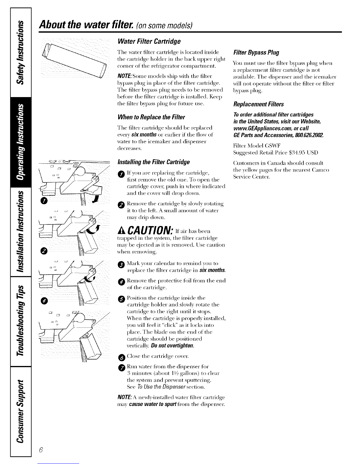
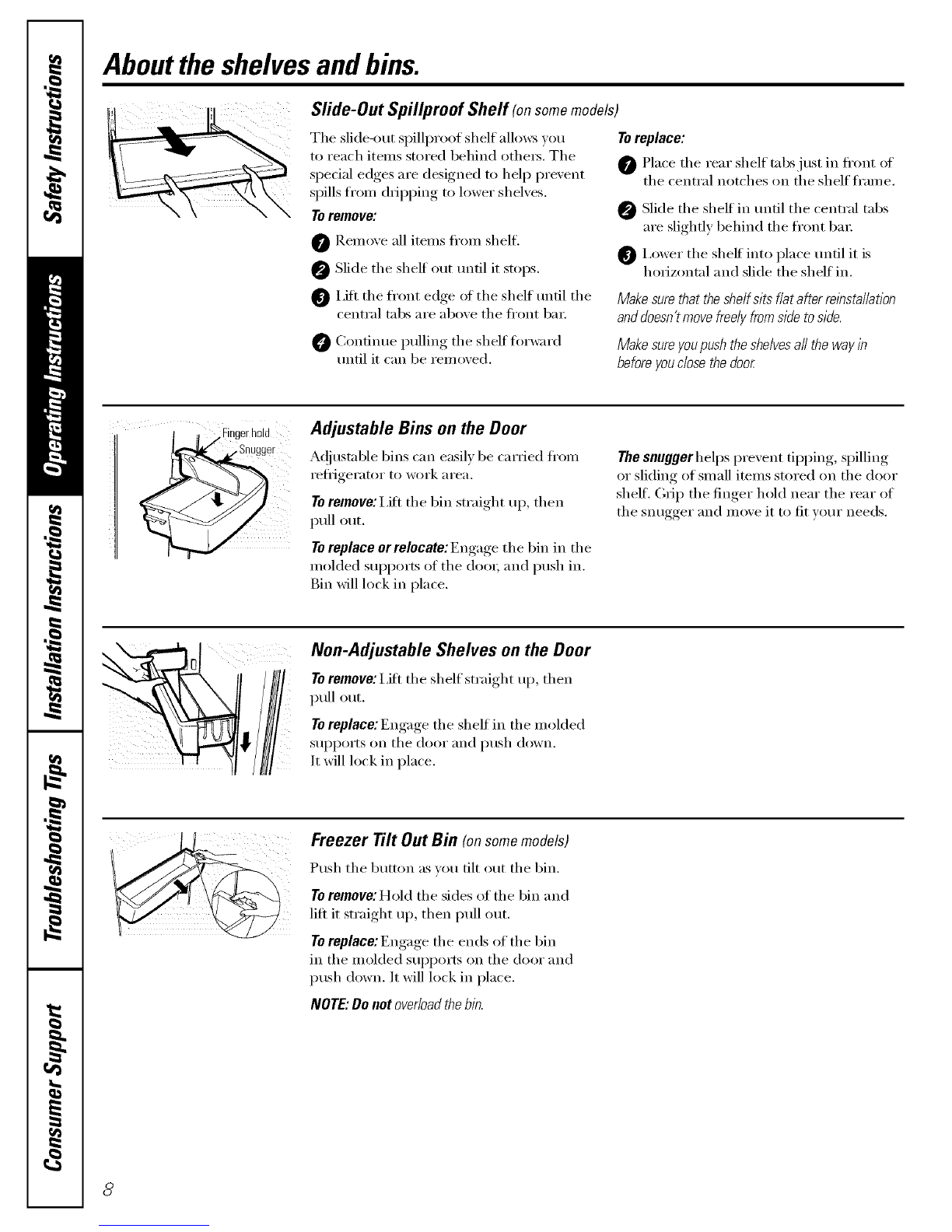
Crisper Removal
To Remove:
These drawex_ can be remo_,ed easil)by
lifting up slightly while pulling tile drawer
past the stop location.
When the door cannot be fully opened,
rein ore th e dm wet fi_rth est from the door
first. Make sm'e the drawer closest to the
(loot" is fifllv closed. There is a latch at the
front (ff tile center slide rail. Push down on
the latch and slide the center slide rail, to
which the drawer is attached, away fl'om
the door Remove fl_e drawe_:
Abouttheautomaticicemaker.
A newly-installed refrigerator may take 12-24 hours to begin making ice,
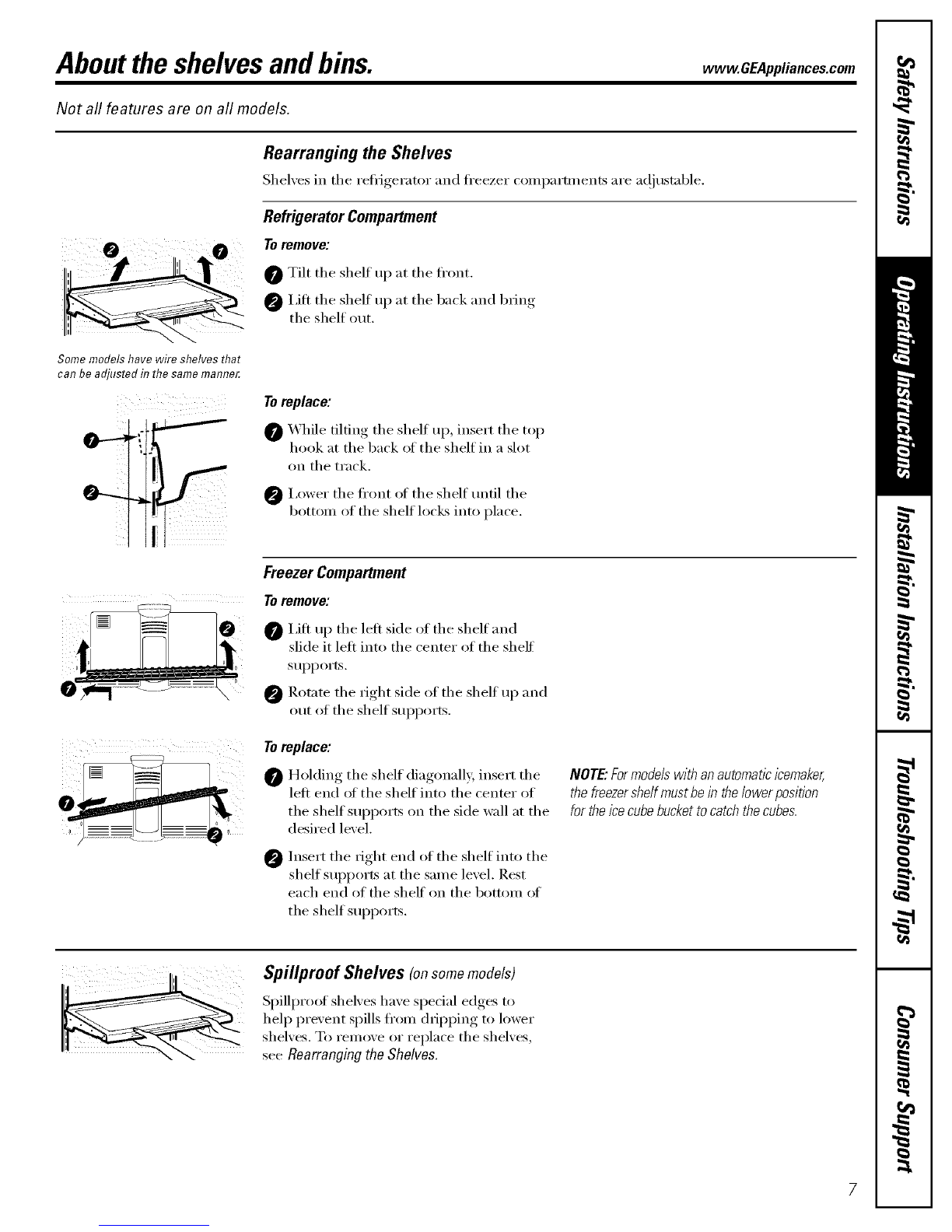
Power
Switch Icemaker
PowerLight
Powerswitch model
! i
FeelerArmin (up)position
theON (down)
position
Feeler arm model
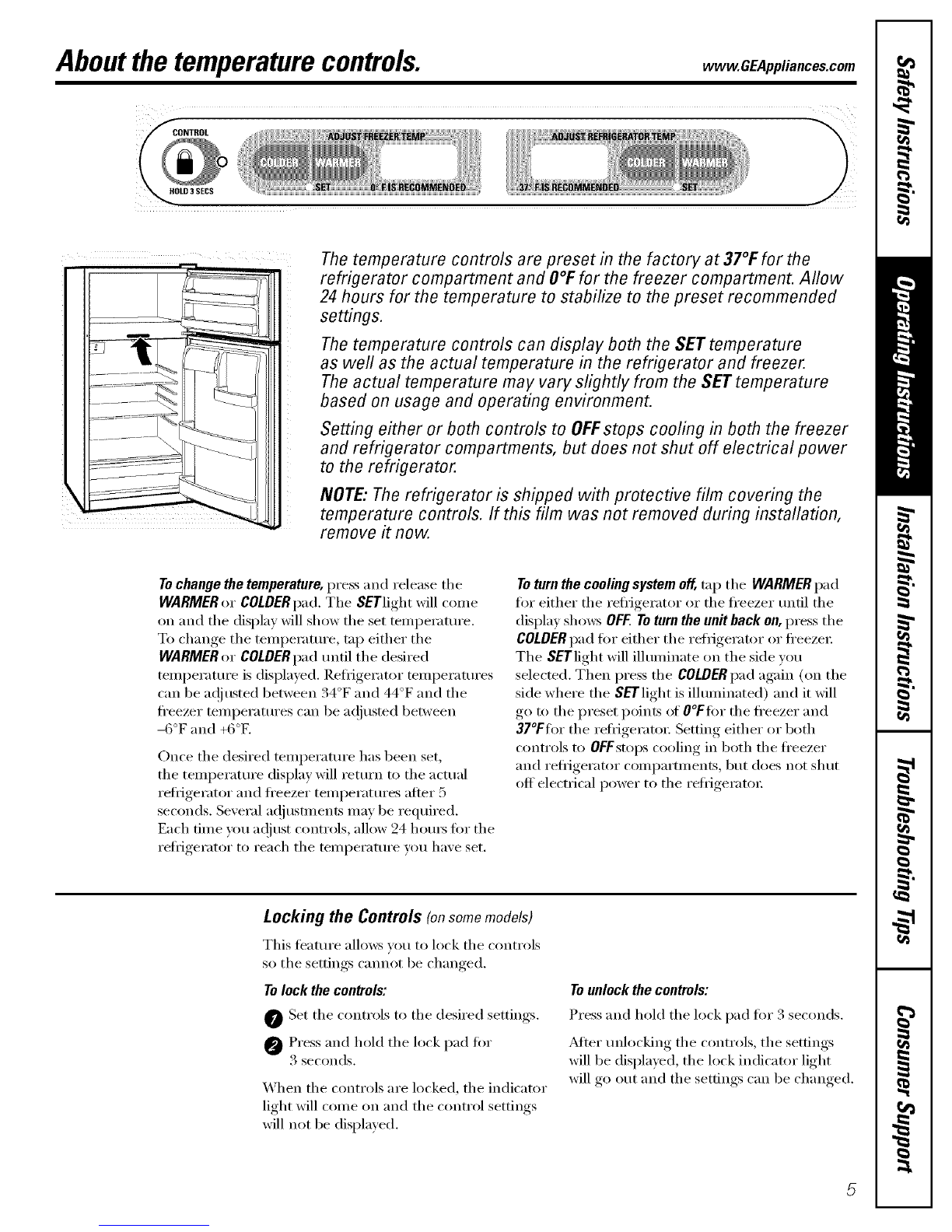
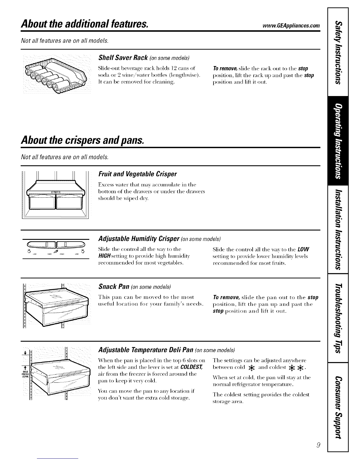
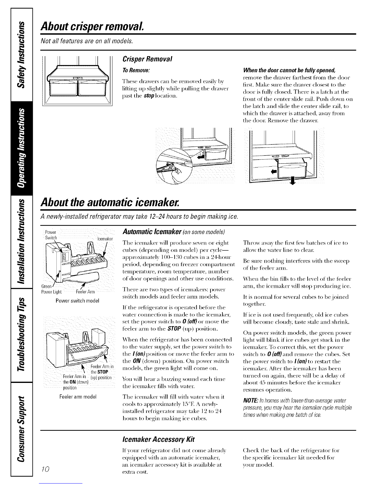
Automatic Icemaker (on some models)
The icemaker will produce seven or eight
cubes (depending on model) per cycle--
approMmately 100-130 cubes in a 24-horn"
period, depending on fl'eezer compartment
teiili)ei'attli'e _ i'ooi/] teiili)ei'attli'e _ ntli/lber
of door openings and other use conditions.
There are two t)pes of icemake_: power
switch models and feeler am_ models.
If tile refl{gerator is operated befiwe tile
water connection is made to the icemaket;
set tile power switch to 0 (off) or move tile
teeler am_ to tile STOP(up) position.
When tile reliJgerator has been connected
to the water sui)i)ly, set the power switch to
tile I (on)position or move tile feeler am/ to
the 0N (down) position. On power switch
models, the green light will come on.
You will hear a buzzing so/md each dine
tile icemaker fills with water;
The icemaker will fill Mth water when it
cools to approximately 15°E A newly-
installed refrigerator may take 12 to 24
hom_ to begin making ice cubes.
Throxx a'_av tile first tex_ batches of ice to
allow the water line to clea_:
Be sure nothing intetTeres with tile sweep
of tile feeler amL
_]/en tile bin fills to tile level of tile teeler
amL tile icemaker will stop producing ice.
It is nomml for several cubes to be joined
together:
If ice is not used fl'equenfl> old ice cubes
will become cloud> taste stale and shrink.
On power switch models, tile green power
light will blink if ice cubes get stuck in the
icemaket: To correct this, set tile power
switch to 0(Off) and remove tile cubes. Set
the power switch to I(on) to restart the
icemake_; _dter tile icemaker has been
turned on again, there will be a delay ot
about 45 minutes bet0re tile icemaker
I'eStlllleS ol)eI_ltion.
NOTE:Inhomeswithlower-than-averagewater
pressure,youmayheartheicemakercyclemultiple
timeswhenmaklbgonebatchofice.
10
Icemaker Accessory Kit
If yore" refl_igerator did not come ah'eadv
equipl)ed with an automatic icemake_;
an icemaker accessory kit is a_ filable at
extra cost.
Check tile back of tile refl{gerator fi)r
tile specific icemaker kit needed fin.
VO//I" II/odd.