manuals.online logo
Brands
  1. Home
  2. •
  3. Brands
  4. •
  5. GE
  6. •
  7. Smoke Alarm
  8. •
  9. GE TX-6212-03-1 Assembly instructions

GE TX-6212-03-1 Assembly instructions

GE
Securit
y
TX-6212-03-1 Wireless Smoke
Detector Installation Sheet
1
2
3
4
5
6
© 2010 UTC Fire & Security. All rights reserved.
1 of 4
P/N 55370151 • REV 1.0 • ISS 19OCT10
2 of 4 P/N 55370151 • REV 1.0 • ISS 19OCT10
Description
The TX-6212-03-1 is a LearnMode wireless smoke detector
designed for use in a security system with a compatible control
panel. The detector is designed to comply with
EN14604:2005/AC:2008.
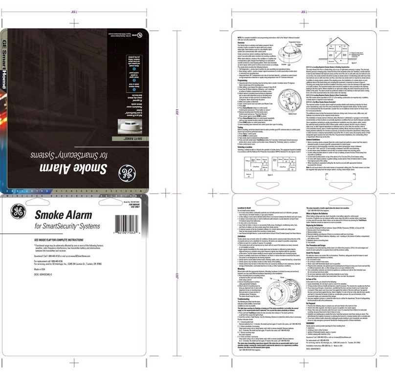
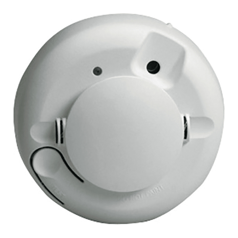
The detector has a status LED (Figure 1, item 1), a Silence/Test
button (Figure 1, item 2), and a built-in sounder for alarm
indication.
The status LED flashes every eight seconds to indicate normal
status (no alarm). When smoke is detected, the status LED
changes from flashing to on, the built-in sounder is activated, and
an alarm signal is sent to the control panel.
The detector sends a supervisory signal to the control panel every
64 minutes to confirm its status.
The detector also includes the following features:
• A tamper switch that triggers a tamper signal transmission
when the detector is removed from its mounting base
• Self-diagnostics to monitor detector sensitivity and
operational status
• A replaceable optical chamber for easy maintenance
Installation
Caution: Refer to your control panel documentation for detailed
information on the corresponding communications, configuration,
and test requirements.
Where to install a smoke detector
Regulations for smoke detector installation vary from region to
region. For more information, contact your fire service or local
authority having jurisdiction.
In addition to local regulations, use the following installation
guidelines to optimize performance and reduce the chance of
false alarms from the detector:
• Install ceiling-mounted detectors in the center of a room or
hallway at least 10 cm (4 in.) from any walls or partitions.
• Install wall-mounted detectors so that the top of the detector
is 15 to 30 cm (6 to 12 in.) below the ceiling.
• Install all detectors within 30 m (98 ft) of the control panel
• Install detectors away from air conditioners, fans, and any
other devices that may interfere with smoke entering the
detector.
• Install detectors on a firm permanent surface away from
large metallic objects.
• Ensure that the environmental conditions (temperature,
relative humidity) comply with those indicated in the technical
specifications.
Verify communication
Communication between the detector and the control panel
should be verified prior to installation.
To verify communication:
1. Put the control panel into the corresponding test mode.
2. From the proposed installation location, press and hold the
detector Silence/Test button for four seconds, and then
release it. After a short delay the status LED is activated (on)
and the detector transmits a test alarm signal to the control
panel.
3. Check that the signal is received by the control panel and
that the signal strength is adequate. If not, relocate the
detector and perform the test again.
4. When adequate communication is confirmed, exit the test
mode.
Installation
To install the detector:
1. Remove the detector from the mounting base by turning the
detector counterclockwise about 15 degrees (Figure 2).
2. Slide the battery cover (Figure 3, item 1) away from the
detector to unsnap it and lift it off. Insert two 3V lithium
CR123A batteries observing the correct polarity (as indicated
in the battery compartment).
Note: the detector cannot be attached correctly to the
mounting base if the batteries are not installed.
3. Remove the red plastic cover from the detector. The detector
is shipped with the cover for protection against dust on
construction sites.
4. Using the two screws and anchors provided, mount the base
in the required location.
5. To attach the detector to the mounting base, line up the
alignment tab on the detector (Figure 4, item 1) with the
alignment arrow on the mounting base (Figure 4, item 2) and
insert the detector into the base and turn clockwise
approximately 15 degrees. The detector should snap firmly
into place.
6. Verify that the detector communicates with the control panel
and test the detector as described in Testing the detector, on
page 3.
Operation
Status LED indications
The status LED indications are as follows:
LED indication Status Description
Flashing Normal The status LED flashes every eight
seconds to indicate normal status
On Alarm Alarm (smoke has been detected)
Off Fault Maintenance is required. Check the
control panel for further
information.
The Silence/Test button
The Silence/Test button operations are as follows:
Operation Description
Silence the low
battery alert
Press the button for one second to silence the
audible low battery alert (the alert resumes after
24 hours if the batteries are not replaced).
Sensitivity and Alarm
test
Press the button for four seconds to perform a
sensitivity test and to send a test alarm signal to
the control panel
Operation Description
Remote monitoring
station alarm test
Press the button for fifteen seconds to send a fire
alarm signal to the remote monitoring station.
Important: To avoid a fire department dispatch,
contact the remote monitoring station or put the
control panel into the corresponding test mode
before performing this test.
Testing the detector
Siren and signal integrity test
Test each detector to verify that siren and signal integrity
responses are adequate.
Note: Refer to your control panel documentation for detailed
information on system response.
To test the siren and signal integrity:
1. Put the control panel into the corresponding test mode.
2. Press and hold the detector Silence/Test button for four
seconds, and then release it. After a short delay the status
LED is activated (on) and the detector transmits a test signal
to the control panel.
3. Listen for the appropriate response from system sirens to
determine signal integrity from the detector to the panel.
4. Exit the test mode at the control panel.
Smoke test
Caution: To avoid a fire department dispatch, contact the remote
monitoring station or put the control panel into the corresponding
test mode before performing this test.
Smoke detectors should be tested annually using canned smoke.
Follow the instructions on the can.
During the test, the status LED is on and the detector sounds a
continuous tone. The detector automatically resets when smoke is
no longer present.
A detector that fails to activate with the smoke test may require
cleaning. If the detector still fails to activate after cleaning, return
the unit for service.
Sensitivity test
To start the sensitivity test, press and hold the Silence/Test button
for four seconds, and then release it. The status LED flashes one to
nine times to indicate the test results (shown below).
Flashes Description
1 Self-diagnostics failure. Return the detector for service or
replacement.
2 to 3 The detector is becoming insensitive. Clean the optical
chamber and repeat the test. If the error persists, replace the
detector.
4 to 7 The detector is within the normal sensitivity range
8 to 9 The detector is becoming too sensitive. Verify that the optical
chamber is installed correctly. Clean the optical chamber
and repeat the test.
Maintenance
Replacing the batteries
The detector is powered by two 3V lithium CR123A batteries.
When batteries are low, the detector status LED is off and an
audible alert sounds every 45 seconds until the batteries are
exhausted. Replace both batteries immediately.
Note: The low battery alert can be silenced for 24 hours by
pressing the Silence/Test button.
Always test the detector after replacing the batteries.
Cleaning the detector
Clean the detector with a dry or damp cloth to keep it free from
dust and dirt. Clean the detector interior at least once a year and
replace the optical chamber as described below.
Replacing the optical chamber
To replace the optical chamber:
1. Remove the detector from the mounting base.
2. Remove the batteries.
3. Slide a flat-bladed screwdriver into the slot on the detector
cap and gently push down to pry the cap off (Figure 5).
4. Squeeze the existing optical chamber where indicated and
pull it up and away from the detector and discard (Figure 6).
5. Blow out or use a soft-bristled brush to remove dust and dirt
from the smoke chamber base.
6. Align the new optical chamber with the base and snap down
into place.
7. Replace the detector cap and turn clockwise approximately
15 degrees until it snaps into place.
8. Install the batteries and the battery cover.
9. Attach the detector to the mounting base.
10. Test the detector as described earlier in this document.
Specifications
Current consumption (nominal)
Standby
Alarm
Test
35 uA
70 mA
2 mA
Batteries 2 x 3 V lithium CR123A
Estimated battery life 4 to 6 years
Low battery indication Audible alert every 45 seconds
Sensitivity 0.14 +/- 0.04 dB/m
Drift compensation adjustment 1.64%/m (0.5%/ft.) max.
Sounder 85 dBA at 3 m (continuous tone)
Supervisory signal Every 64 minutes
RF frequency 868 MHz
Typical RF output 12 mW
RFI immunity Complies to EN14604:2005/AC:2008
Modulation type AM
Transmitter ID Preprogrammed. 1 million codes
P/N 55370151 • REV 1.0 • ISS 19OCT10 3 of 4
Environmental
Operating temperature
Storage temperature
Relative humidity
4 to 38°C (40 to 100°F)
−34 to +60°C (−30 to 140°F)
10 to 90% noncondensing
Dimensions (W x H)
Detector
Mounting base
14.2 x 6.1 cm (5.6 x 2.4 in.)
13.7 x 1.17 cm (5.4 x 0.46 in.)
Regulatory information
Certification
CPD certificate 1134-CPD-039
Compliant to EN14604:2005/AC:2008
Year of manufacture The first two digits of the product serial
number (located on the product
identification label) are the year of
manufacture.
European Union directives 1999/5/EC (R&TTE directive): Hereby, UTC
Fire & Security declares that this device is
in compliance with the essential
requirements and other relevant
provisions of Directive 1999/5/EC.
Manufacturer UTC Fire & Security
Shanghai UTC Fire & Security Electronics,
1st Floor No. 2 Building No. 211 Qinqiao
Road, Jinqiao Export Processing Zone,
Pudong New Area 201206, Shanghai,
China.
Authorized EU manufacturing
representative:
UTC Fire & Security B.V.
Kelvinstraat 7, 6003 DH Weert,
Netherlands.
Contact information
For contact information, see www.utcfireandsecurity.com.
4 of 4 P/N 55370151 • REV 1.0 • ISS 19OCT10

Other GE Smoke Alarm manuals

GE FHSD720C User manual

GE

GE FHSD720C User manual

GE ESL 700 Series User manual

GE

GE ESL 700 Series User manual

GE 60-992-900 User manual

GE

GE 60-992-900 User manual

GE Z630-3 Assembly instructions

GE

GE Z630-3 Assembly instructions

GE 429CT User manual

GE

GE 429CT User manual

GE ESL 570N User manual

GE

GE ESL 570N User manual

GE 782136710441 User manual

GE

GE 782136710441 User manual

GE ESL 560N Series User manual

GE

GE ESL 560N Series User manual

GE TX-6010-01-1 User manual

GE

GE TX-6010-01-1 User manual

GE ADTGC-HDVM Assembly instructions

GE

GE ADTGC-HDVM Assembly instructions

Popular Smoke Alarm manuals by other brands

Abus RM40Li user manual

Abus

Abus RM40Li user manual

jablotron SD-283ST quick start guide

jablotron

jablotron SD-283ST quick start guide

Carrier KIDDE 900-CUAR-V user guide

Carrier

Carrier KIDDE 900-CUAR-V user guide

Bellman & Symfon BE1480 manual

Bellman & Symfon

Bellman & Symfon BE1480 manual

Bosch MAGIC.SENS series product manual

Bosch

Bosch MAGIC.SENS series product manual

SmokeCloak VALI series quick start guide

SmokeCloak

SmokeCloak VALI series quick start guide

AJAX FireProtect quick start guide

AJAX

AJAX FireProtect quick start guide

Gentex 9000 SERIES installation instructions

Gentex

Gentex 9000 SERIES installation instructions

nedis WIFIDS20WT user manual

nedis

nedis WIFIDS20WT user manual

AJAX FireProtect user manual

AJAX

AJAX FireProtect user manual

Det-Tronics X9800 instructions

Det-Tronics

Det-Tronics X9800 instructions

System Sensor D2-AUS Installation and maintenance instructions

System Sensor

System Sensor D2-AUS Installation and maintenance instructions

Apollo AlarmSense manual

Apollo

Apollo AlarmSense manual

family first FFP9VH user manual

family first

family first FFP9VH user manual

SPECAVTOMATIKA DOKA Instruction

SPECAVTOMATIKA

SPECAVTOMATIKA DOKA Instruction

x-sense XS01-WR user manual

x-sense

x-sense XS01-WR user manual

Bacharach True-Spot 21-7012 Instructions and parts list

Bacharach

Bacharach True-Spot 21-7012 Instructions and parts list

brennenstuhl RM C 9010 operating instructions

brennenstuhl

brennenstuhl RM C 9010 operating instructions

manuals.online logo
manuals.online logoBrands
  • About & Mission
  • Contact us
  • Privacy Policy
  • Terms and Conditions

Copyright 2025 Manuals.Online. All Rights Reserved.