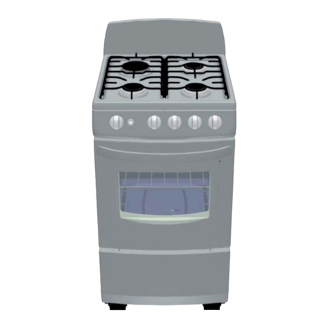
GE JGBS14PCD Installation guide

– 1 –
GE Appliances
General Electric Company
Louisville, Kentucky 40225
GE Appliances
GE Cordless Gas Range
Models: JGBS14PCD RGB518PCD
TB05-12
Training Bulletin
December 2012
INTRODUCTION
In compliance with Department of Energy requirements,
GE has introduced 2 cordless battery-powered ignition
30-in. free-standing gas ranges:
GE model JGBS14PCD
Hotpoint model RGB518PCD
RANGE FEATURES
• Standing gas pilots have been replaced with
electronic spark ignitors.
• Surface burners use spark ignition similar to previous
models.
• Ovens use a pilot burner and thermocouple
configuration.
• Oven thermostat controls both oven burner and oven
pilot operation.
• Gas is used only when surface burners or oven are
turned on.
• AC voltage not required or used for range operation.
• The ignitors are powered by a 9-volt battery.
• The battery is conveniently located in a
compartment on the front of the range behind the
broiler door.
• GE models include a low battery indicator light
located on the left side of the control panel.
GE model
JGBS14PCD
Hotpoint model
RGB518PCD

– 2 –
THERMOCOUPLE ―HOW IT WORKS
The thermocouple is an electronic device that senses if
the pilot flame is the proper size and hot enough to ignite
natural gas or propane fuel to the burner.
Note: The thermocouple is a part of the pilot assembly.
To replace the thermocouple, order a pilot assembly.
The thermocouple (technically called a thermocouple
junction) is a device that contains two metal wires
welded at the ends, forming a sensor, and placed inside
a protective metal case. The thermocouple sensor is
found at the end near the pilot burner and is designed
to be placed in the hottest part of the pilot flame. The
other end is connected to the oven thermostat. As the
thermocouple heats up, it produces a small amount of
electricity (3 to 20 millivolts) that is applied to a small
electromagnetic valve in the oven thermostat. The
energized electromagnetic valve will keep the pilot gas
valve open.
TO LIGHT THE OVEN:
1. Turn thermostat knob to the Pilot position.
MINI-MANUAL AND LP CONVERSION KIT:
The Mini-manual and the LP conversion kit are attached
to the back of the range near the gas inlet pipe with a
1/4-in. hex-head screw.
1. Push the thermostat knob in completely and hold it
in for 10 seconds. This 10-second period allows gas
to be supplied and ignited at the pilot burner and
heat applied to the thermocouple.
2. Turn the thermostat knob to the desired temperature.
This allows gas to be supplied to the oven burner and
ignited.
3. Open the oven door and check for burner flame.
3. Lift the back of the oven bottom then remove the
bottom from the oven cavity.
4. Locate the oven burner pilot at the left rear of the
oven burner.
5. Hold a lit match to the oven burner pilot. Turn the
oven control knob to the Pilot position and push it in
completely.
6. After the pilot is lit, continue to hold in firmly on the
knob for 10 seconds before releasing.
7. Pilot should remain lit, if not, repeat steps 5 and 6.
8. Replace oven bottom, racks, and door.
9. Turn knob to the desired temperature setting. Oven
will operate normally.
10. Turn oven control knob to Off when finished baking.
Note: The oven may be lit with a match and operated
normally even if the battery is too weak to activate the
spark system.
To match-lite the oven burner:
1. Remove the oven door and oven racks.
2. Remove the two 1/4-in. hex-head screws at the back
of the oven bottom.
Thermocouple
Pilot Burner
Pilot Assembly

– 3 –
BATTERY-POWERED IGNITION
The range is equipped with a 9-volt battery. The battery
supplies power to the spark module that operates the
spark ignitors.
The battery is located in a compartment on the front left
corner of the range behind the broiler door.
Depending on usage, battery life is estimated to be 12 to
18 months.
To replace the battery:
1. Open the broiler door.
2. Insert a flat blade screwdriver or coin in the slot at
the bottom edge of the battery tray.
3. Lift and pull out the battery tray from the receptacle.
When to replace the battery:
• When the amount of time between sparks exceeds
1 second.
• When the green battery indicator light (GE models)
fails to glow during sparking.
• When inspection of the battery shows leakage.
Note: If battery leakage has damaged the battery tray
receptacle terminals, replace the receptacle.
Broiler Door
To replace the battery tray receptacle:
1. Remove the battery tray. (See To replace the
battery, follow steps 1 through 3.)
2. Remove the 2 Phillips-head screws from the front of
the battery tray receptacle.
3. Pull the receptacle out and disconnect the wire
harness.
4. Insert a new battery in the battery tray.
5. Slide the battery tray back into the receptacle.
Important: Replace with standard 9-volt alkaline battery.
Follow all state and local requirements for disposing of
the old battery.
Slot
Coin
Once the pilot gas valve is open, turning the thermostat
knob to a temperature setting will allow gas to be
supplied to the oven burner. Oven temperature can then
be regulated by the thermostat. If the thermocouple
does not sense enough heat from the pilot flame (such
as when the pilot is out), then the thermostat shuts off
the gas supply to both the pilot and oven burners.

– 4 –
THERMOSTAT
The oven thermostat utilizes a thermocouple to sense
the presence of the pilot flame and a capillary to sense
oven temperature.
To replace the oven thermostat:
1. Turn off the gas supply to the range.
2. Open oven door and remove the capillary from clips
on the back wall of the oven cavity.
3. Lift main top to the open position and remove the
knobs.
4. Remove three 1/4-in. hex-head screws from the
bottom of the control panel.
SPARK MODULE
The spark module, similar in appearance to previous
models, is now powered by the 9-volt battery.
The module is attached to the inside of the module cover
with two 1/4-in. hex-head screws. It is necessary to
remove two 1/4-in. hex-head screws and module cover
to access the module.
5. Remove the 2 Phillips-head screws from the front of
the control panel.
6. Pull the control panel off the range.
7. Using a small flat blade screwdriver, remove the
C-clip and pull the spark ignition switch off the
thermostat shaft.
8. Remove the 5/8-in. hex nut that attaches the oven
burner gas tube.
9. Remove the 3/8-in. hex nut that attaches the pilot
gas tube.
10. Remove the 5/16-in. hex nut that attaches the
thermocouple.
11. Remove the Phillips-head screw (5/16-in. hex nut)
from the thermostat bracket.
12. Lower the thermostat from the gas manifold pipe
and remove the capillary from the range.
Module Cover
C-clip
Spark Ignition Switch
Thermocouple
Oven Burner Tube
Pilot Tube
Spark Module
This manual suits for next models
1
Other GE Stove manuals
Popular Stove manuals by other brands

Vogelzang International
Vogelzang International BK100E owner's manual

Super Ego
Super Ego SEH003300 quick start guide

Monaco
Monaco 134 06 02 Technical manual

Palazzetti
Palazzetti ECOFIRE IDRO HAMMER PRODUCT TECHNICAL DETAILS

MCZ
MCZ DECO' AIR 8 M1 Use and installation manual

Solution
Solution SLE42s instruction manual

Navigator Stove Works
Navigator Stove Works NSW4 Installation and operating instructions

COMPANION
COMPANION COMP202 owner's manual

FRANCO BELGE
FRANCO BELGE Normandie 174 10 44 Technical manual

Primus
Primus 3279 GRAVITY II EF Instructions for use

ADURO
ADURO P1 series Cleaning instructions

Ravelli
Ravelli Chronos Use and maintenance manual