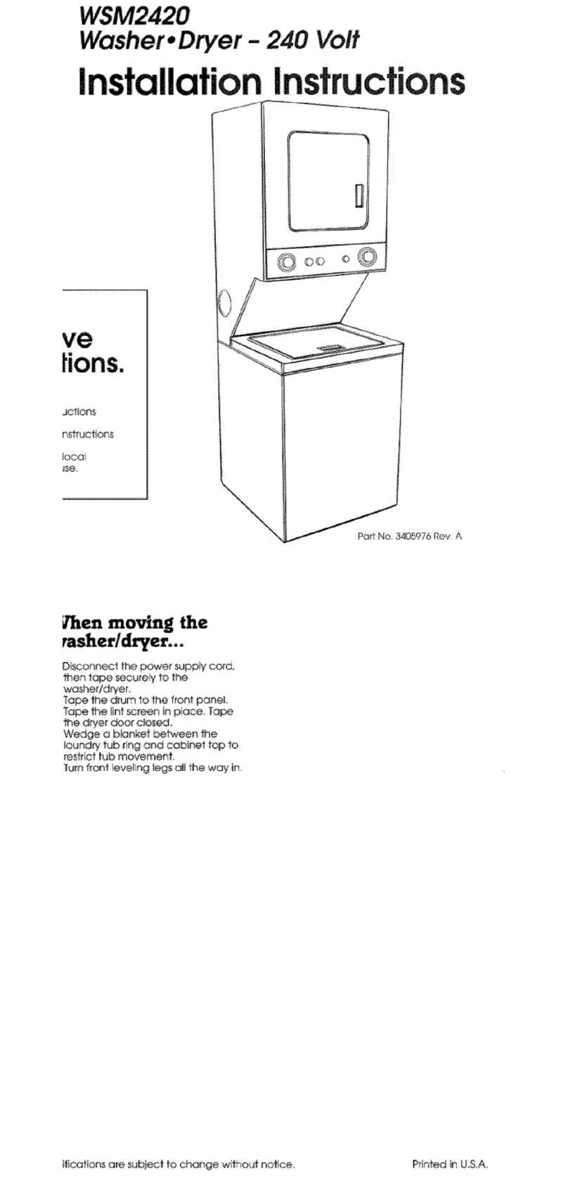
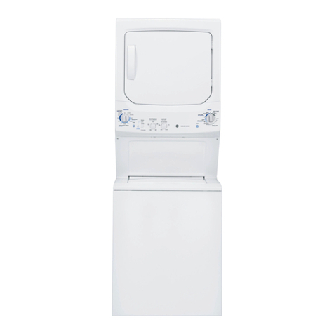
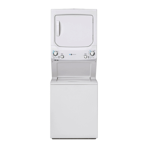
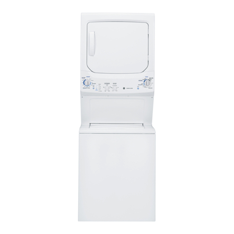
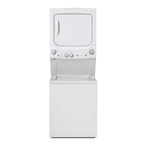
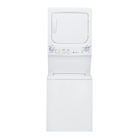
GE Spacemaker WSM2780R User manual

TECHNICIAN
MANUAL
GEAS 061156

WASHER
INDEX
PAGE:
1.
WASHER TOP PANEL
2. SNUBBER RING
3. WASHER COMPONENTS AND PARTS
4.
TUB SPLASH COVER REMOVAL OR REPLACEMENT
5. TUB SPLASH COVER GASKET
6.
INNER WASH BASKET
7.
TRUNNIONIWATER SEAL
8.
OUTER TUB ASSEMBLY
9.
STABILIZING SPRINGS
10.
WATER PUMP ASSEMBLY
11.
DRIVE MOTOR WATER SHIELD
12. WASHER DRIVE MOTORIBELT
13. DRIVE MOTOR BELT IDLER ARY
14.
WATER INLET HOSE AND NOZZLE
15. LID AND EINGES
16. WASHER BASE
17.
DRAIN HOSE CHECK VALVE
18.
DRAIN HOSE CONNECTOR
19.
DRIVE MOTORIELECTRICAL
20. DRIVE MOTORITESTING
21. CAPACITOR
22. TESTING CAPACITOR
23. WASHER TIMER TESTING
24. CONSOLE AND CONTROLS
25.
WATER LEVEL PRESSURE SWITCH
26. TESTING WATER LEVEL PRESSURE CONTROL SWITCH
27. REPLACE WATER LEVEL PRESSURE CONTROL SWITCH
28. WATER TEMPERATURE SELECTOR SWITCH
29. WATER INLET MIXING VALVEIOPERATION
30. TEST WATER VALVE
31.
LID SWITCH AND LOCK ASSEMBLY
32.
LID SWITCH LID LOCK TESTING
a
GEAS 061157

WASHER FEATURES/REQUIREMENTS
FEATURES
-
REO
U-IIREM
ENS
--
-
CAPACITY
.....
2.7
CU. FT.
...
WASH CYCLE SELECTIONS.
3
REGULAR
PERMANENT PRESS
DELICATE
WASH/RINSE TEMPERATURE SELECTIONS
...
3
SELECTIOtjs TEMPERATURES
HOT
............
HOT
/
COLD
W
A
R
M
.
.........
.
W
A
R
M
'
/
C
O
L
D
COLD
...........
COLD
/
COLD
NOTE: WARM MIX RATE
...
50% HOT. 50% COLD
WATER LEVEL SELECTIONS
...
3
SMALL (WATER IN TUB 5.2
"
TO 6.4
"
)
MEDIUM (WATER IN TUB 8.4
"
TO 10.0
"
)
LARGE (WATER IN TUB 11.9
"
TO 13.5
"
)
CONTROLS
ROTARY TIME..PUSH TO SET; PULL TO START
WASH
/
RINSE TEMPERATURES..ROTARY SWITCH
WATER LEVEL
...
ROTARY PRESSURE SWITCH
WATER SUPPLY
HOT
&
COLD FAUCETS
-
Must be
within
42
"
of appliance water
inlet hose connections and
must
be
3/4"
garden hose
type.
WATER PRESSURE
Must be
10
-
120 PSI
with a
maximum unbalance (hot vs.
cold) of
10 PSI.
WATER TEMPERATURE
Water heater must set to
deliver
140
-
150
F
IN THE
WASHER
when
HOT
wash is
selected.
SHUT
-
OFF VALVES
Both hot and cold shut
-
off
valves should be supplied.
DRAIN HEIGHT
33
"
MIPiIMUM.
96
"
MAXIMUM
WASH
/
SPIN SPEEDS STANDPIPE DIAMETER
WASH SPEED..71/77 AGITATOR STROKES
/
MIN
1
"
MINIMUM
with
an
air gap
SPIN SPEED..610/630 RPM
around the drain hose.
DRIVE MOTOR DRAIN RATE
1/2 HP
@
120 VOLTS
The drain or standpipe mrrst
be
capable of accepting
16
LINT FILTER
GALS/MIN.
FULL WIDTH INNER DOOR
(POLYESTER SCREW) (REMOVABLE)
SIPHON BREAK KIT
WH49X228
Siphon Break Kit must
be used along with the
furnished hose. coup1
i
ng and
clamps
if
the standpipe is
less than
33
"
high.
ELECTRICAL
120/240
or
120/208
volt single
phase,
60HZ
individual branch
circuit protected by
30
amp
time
-
delay fuses or circuit
breaker.
GEAS 061158

The WSM2700 and 2780 are unitized
washers with gas or electric dryer
assembled as a high/low appliance
with the dryer at top. Controls for
the washer and dryer are located at
bottom of dryer front with the dryer
controls on the left and washer
controls at the right. Each
operates as a separate appliance and
may be operated simultaneously.
WAR
RANTV
FULL ONE YEAR
-
WARRANTY:
All
parts and labor for in
-
home
service for one year after original
date of purchase.
LIMITED ADDITIONAL FOUR
-
YEAR WARRANTY:
Any part of the washer transmission
that fails within, in the second
through the fifth year from original
date of purchase, will be furnished
free of charge. Service trip and
labor charges are not warranted.
Refer to back cover of SPACEMAKER
LAUNDRY
Use and Care book for
complete warranty information.
PRODUCT RATING PLATE
The product rating plate containing
aqency approvals is located on top
of the appliance near the left front
corner,
A
second model and serial
lah~lis locatsd on the inner face
of
tho dryer door for the
convenience of
tho
coiis\rmer and
scrv
i
c~.
PRODUCT
CUT
-
A
-
WAY
VIEVJ
27"
LAUNDRY
CENTER
GEAS 061159

WASHER
TOP
PANEL
The top is secured to the washer
cabinet from the inside. The washer
lid and hinge assembly mounts to
the washer top through grommets, and
the lid is counterbalanced by a coil
spring and a spring steel retainer.
THE
A.
PANEL MAY BE
REMOVED AS FOLLOWS:
Remove two screws securing the
dryer front service access
panel.
Remove the washer front service
panel.
Remove two screws securing the
washer top panel and lid
assembly to the cabinet front
sides.
Remove two screws securing the
right rear corner washer top
panel hinge support
Disconnect the washer lid lock
switch terminal connector.
WASHER
UD
Remove the waher top panel and
1id assembly.
Remove two screws and gasket
securing hinge to lid.
Remove lid hinge from washer top
WASHER
TOP
panel and grommet.
Remove lid hinge cam (RH).
Remove lid assembly.
Remove one screw securing
(RH)
hinge spring, and one screw
1.
securing (RH) hinge support.
Remove lid hinge grommets.
Remove two screws securing lid
strike and lid rubber bumpers.
Remove bleach cup dispenser, and
screw securing 1id lock.
Remove two screws securing 1id
lock.
Reverse this procedure to
reassemble.
GEAS 061160

SNUBBER
RING
The snubber ring assembly is made of
a polypropylene ring with teflon
strips secured to the upper and
lower edges. The top edge of the
ring is identified by an arrow
molded into the outer surface. The
snubber ring fits between the raised
dome base of the tub and
transmission assembly.
TO
REMOVE
OR
REPLACE SNUBBER RING
A. Remove the washer front service
panel.
B. Remove the washer top panel and
lid assembly.
C.
Disconnect the front vertical
and horizontal springs from the
base pan.
D.
Place a
2
"
x
4
"
block under
drive motor section of leg and
dome assembly, carefully pry up
the washer tub and transmission
assembly off base.
E.
Using a wire with a hook end
reach under and pull out snubber
ring.
F
Install new snubber ring with
arrow pointing up.
G.
Reverse procedure to reassemble
GEAS 061161

WASHER COMPONENTS AND PARTS
I
AGITATOR AND CAP
The polypropylene agitator and cap
are centered in the inner wash
basket. The cap is threaded into
the agitator drive block and can be
removed by turning counter
clockwise. The agitator can be
lifted off the drive blaock after
the cap is removed. The drive block
is splined and the agitator fits
tight to the block. Upward pressure
will be needed to free the agitator
from the drive block.
TO
REMOVE
OR
REPLACE AGITATOR AND
CAP
:
A. Raise washer lid.
B.
Remove agitator cap by turning
counter clockwise.
C.
Lift out agitator.
D. Install new agitator and/or cap.
E.
Reverse procedure to reassemble.
)
DRIVE BLOCK
The drive block is fastened to the
agitator drive shaft with a stud
bolt.
It
drives the agitator and
provides a means of adjusting the
clearance between the lower edge of
the agitator and tub. The drive
block height is adjusted with shims
3/16
"
minimum, 5/16
"
maximum. A
drive block puller is required to
remove the drive block.
TUB SPLASH COVER
The polypropylene tub splash cover,
which prevents water from splashing
over the top, has a molded rear 1ip
to prevent splash from the
fill
hose
and nozzle assembly. The splash
cover includes a bleach cup drain
area. A sealing gasket in a groove
around the circumference of the
s~lashcover snaps over the outer
tub assembly
-
AGITATOR CAP
TUB SPLASH
5
COVER
-
-
-
GASKET
-L
P,
AGITATOR
-
-
L-
GEAS 061162
TUB
SPLASH COVER REMOVAL OR REPLACEMENT
A. Remove the dryer front service
panel.
B. Remove the washer front service
panel.
C. Remove the washer top panel and
1id assembly.
D.
Release the water level pressure
control tube from the retainer
of the tub splash cover.
E.
Use a flat bladed screwdriver to
pry outward the twelve locking
tabs securing the splash cover
to the outer tub assembly.
F.
Remove tub splash cover and
gasket seal assembly.
G.
Install new tub splash cover;
make sure the sealing gasket is
in
place before snapping cover
into place.
NOTE: THE TUB SPLASH COVER CAN BE
INSTALLED INCORRECTLY. POSITION THE
BLEACH CUP DRAIN AREA DIRECTLY
OVER
THE WASHER DRIVE MOTOR ASSEMBLY AND
MAKE SURE ALL MOUNTING TABS ARE
SNAPPED SECURELY
OR
A LEAK DURING
WILL OCCUR DURING THE SPIN CYCLE.
SECURING THE THREE REAR MOUNTING
TABS FIRST IS RECOMMENDED.
H. Reverse procedure to reassemble.
TUB
SPLASH
COVER
TUB SPLASH
COVER
MOUNTING
TABS
(12)
GEAS 061163

TUB
SPLASH COVER GASKET
1
A sealing gasket (plastic rubber),
in a groove around the circumference
of the splash cover, snaps over the
outer tub assembly for a water tight
seal.
TO REMOVE OR REPLACE TUB SPLASH
COVER GASKET:
A. Remove washer and dryer front
service panel.
B
Remove washer top panel and lid
assembly.
C.
Release the water level pressure
control tube from the retainer
of the tub splash cover.
D.
Use a flat bladed screwdriver to
pry outward the twelve locking
tabs securing the splash cover
to the outter tub assembly.
E.
Remove tub splash cover.
F.
Install new cover and gasket.
G.
Reverse procedure to reassemble
/
CAP
-
w\:.-"
?/A
COVER
GEAS 061164

INNER
WASH BASKET
INNER
The inner wash basket is made of
polypropylene, perforated at the
bottom and sides to separate lint
and soild from the clothes during
agitation, and to extract the water
during spin. The inner wash basket
has a built
-
in upper weight ring
(liquid filled). The inner wash
basket is su
pp
orted by the trunnion,
and is held in place by five bolts.
The trunnion is fastened to the spin
shaft with a lockplate. The
lockplate is located in a milled
area on the spin shaft and is
fastened to the trunnion with two
hex head bolts.
TO
REMOVE
OR REPLACE INNER WASH
BASKET:
A. Remove dryer and washer front
service panel
.
B.
Remove washer top panel and lid
C.
Release the water level pressure
control tube from splash cover.
D.
Remove tub splash cover.
E.
Remove cap and agitator.
F.
Remove
5
3/8"
hex bolts securing
the inner wash basket to the
trunnion.
G.
Slide inner wash basket up and
off the transmission shaft.
H.
Install new inner basket.
I.
Reverse procedure to reassemble.
WASH BASKET
LINT FILTER
The inner wash basket has a self
cleaning lint filter incorporated in
the base of the inner wash basket.
It
is not necessary to clean the
filter, the filter is rinsed clean
during the spin cycle.
TUBE
UPPER
SPIN
BEARING
Inner Wash Basker Mounting Details
GEAS 061165

TRUNNION
The trunnion supports the inner wash
1
basket, and is mounted to the spin
shaft by a locking plate.
TO REMOVE OR REPLACE TRUNNION:
Remove washer and dryer front
service panel
.
Remove washer top panel and lid
assembly.
Release the water level pressure
control tube from the splash
cover.
Remove tub splash cover.
Remove cap and agitator.
Remove
5
3/8"
hex bolts securing
the inner wash basket to
trunnion.
Slide inner wash basket up and
off the transmission shaft.
Loosen two
1/2"
hex bolts
securing trunnion 1ockplate to
milled flat of the spin shaft.
Remove trunnion.
Install new trunnion and apply
loctite.
Reverse procedure to reassemble.
WATER SEAL ASSEMBLY
The water seal assembly sits
underneath the trunnion and inside
the upper bearing housing of the
transmission.
It
seals the water
inside the outer tub. The assembly
consist of a rubber and bronze seal,
and a carbon mating seal surface
mounted on a spring loaded rubber
bellows. The be1lows seal is
pressed into the upper bearing
housing mounted within the outer
tub.
A
slinger washer completes the
assernbl
y.
INNER WASH BASKET !NHER WASH BASKET MOUNTING
BOLTS
MOUNTINGBOLTS TRUNNION LOCK
PLATE
Inner Wash Basket and
Trunn~on
UPPER SPIN TUBE UPPER SEAL
OUTER TUB BRONZE BEARING WATER SEAL
ASSEMBLY
Water
Seal
Assemolv
GEAS 061166

r
TO
REMOVE
OR
REPLACE WATER SEAL
ASM.
A. Remove washer/dryer front
service panel
B.
Remove washer top panel and lid.
C.
Release water level pressure
control tube from the splash
cover.
D. Remove tub splash cover.
E.
Remove cap and agitator.
F.
Remove trunnion and inner
basket.
G.
Remove bronze washer from spin
shaft. Do not lubricate seal,
rep1ace.
OUTER
TUB
ASSEMBLY
The outer tub and air dome is made
of polypropylene and is mounted to
the leg
-
and
-
dome assembly. The
drain hose (tub to pump) and upper
spin bearing are installed onto the
outer tub. The air dome on the tub
side provides the connection for the
pressure switch hose.
TO
REMOVE
OR
REPLACE OUTER TUB
ASM.
A.
Remove washer/dryer front
service panel
B. Remove the washer top panel/lid.
C.
Release water pressure control
tube from the splash cover.
D. Remove tub splash cover.
E.
Remove cap and agitator.
F.
Remove the
5
3/8"
hex bolts
securing the inner wash basket
to trunnion.
G.
Loosen two
1/2"
hex bolts
securing trunnion 1ock plate to
milled flat of the spin shaft.
H.
Remove trunnion.
I.
Remove washer drive be1
t.
J.
Remove outer tub to pump clamp
and hose.
K.
Loosen allen set screw and
remove transmission drive
pulley.
-8-
1
GEAS 061167

Remove two
3/8"
hex bolts
securing transmission to leg and
dome assembly.
Remove threed
1/2"
hex bolts
securing the outer wash tub to
the leg and dome asm.
Li
ft
washer transmission and
outer tub assembly from leg and
dome assembly.
Remove bronze washer from spin
shaft.
Remove water seal, slinger from
bearing housing and slide up and
off spin shaft.
Lift outer wash tub up and off
transmission shaft.
Remove two screws securing upper
spin bearing to the bottom of
the outer wash tub.
Remove outer tub
-
to
-
pump hose
(seal with adhesive upon
reassembly).
Instal
1 to complete assembly.
STABILIZING SPRINGS
.
Each vertical stabilizing spring
hooks into an adjustable tab formed
in the washer base pan and to the
upper end of the leg and dome
assembly. These three springs keep
the washer tub centered during
operation and hold the washer
mechanism against the snubber ring.
The red stained spring must be
installed opposite the washer drive
motor and pump assembly.
Each horizontal stabilizer spring
hooks into the leg
-
and
-
dome and a
raised tab on the washer base pan.
These three springs aid in keeping
the mechanism stable and centered on
I
the crown of the washer base pan.
-1ORfZONl
AL
SPRING
4ERTlCAL
SPRING
AajL--.J:NT
Stabilizer
Sprin~j
GEAS 061168

TO ADJUST VERTICAL STABILIZER
SPRINGS.
When the washer is in the spin
cycle, the tub splash cover (sub
top) should be centered in the
cabinet.
If
off center, adjust each
vertical spring as required.
Excessive out of balance loads may
cause the washer splash cover (sub
top) to strike the cabinet.
Pressure of the leg
-
and
-
dome against
the snubber can be increased or
decreased by equally adjusting the
tension of the vertical springs.
i
Use a pair of vice grip pliers to
adjust springs.
/
WATER
PUMP ASSEMBLY
The water pump
(
a one piece seal
asm.) is mounted avove a water
shield on top of the washer drive
motor by two spring clips
NOTE: Should the washer outer wash
tub be full or partially full of
water, and the washer drive motor is
inoperative, remove the inlet drain
hose clamp. Insert a small bladed
screwdriver along side the drain
inlet hose allowing small flow of
water into water shield. Place a
pan under the overflow to catch
water
INTERIOR
DRAIN
HOSE
\
GEAS 061169

TO REMOVE OR REPLACE PUMP
A. Remove the washer front service
panel.
B.
Remove the drain hose, inlet and
outlet hoses, and clamps from
the water pump assembly. Note:
to gain working space to remove
the water pump, remove the front
outer wash tub to leg
-
and
-
dome
front mounting bolt,
lift
up on
outer wash tub assembly, and
reinstal1 bolt into leg
-
and
-
dome
assembly bolt home.
C.
Remove two spring mounting clips
securing water pump assembly to
washer drive motor. Note: Upon
reassembly, be sure electrical
leads do not become pinched
under spring clips.
D. Lift pump up and off washer
drive motor shaft.
E. Install new water pump assembly.
F.
Reverse procedure to reassemble.
I
DRIVE MOTOR WATER SHIELD
0
The water pump is mounted above the
polypropylene water shield on top of
the washer drive motor by two spring
clips. The drive motor water shield
has molded legs that
fit
into holes
in the drive motor upper end plate.
TO REMOVE
OR
REPLACE DRIVE MOTOR
WATER SHIELD:
A. Remove washer front panel.
B.
Remove drain hose, inlet and
outlet hoses and clamps.
C.
Remove two spring mounting clips
securing water pump to drive
motor.
D. Remove the washer drive motor
shaft slinger.
E.
Lift pump up and off washer
drive motor shaft.
F.
Remove the drive motor water
shield.
G.
Install new shield.
H.
Reverse procedure to reassemble.
DRIVE
MOTOR
GEAS 061170

WASHER DRIVE MOTOR
The washer drive motor is a two
speed, 1/2 h.p., capacitor start,
reversible motor rated at 120 volts,
60 hertz. The connections to the
motor are quick disconnect type
terminal blaocks. The washer drive
motor is mounted to the leg
-
and
-
dome
assembly and drives the transmission
by a pulley mounted on its shaft, a
I
drive belt, and belt idler arm
M
O
T
O
R
SW~CH
D
R
I
V
E
M
O
T
O
R
assembly.
\
TO
REMOVE
OR
REPLACE WASHER DRIVE
MOTOR
:
A.
Remove washer front panel.
B.
Remove the drain hose, inlet and
outlet hoses, and clamps from
the water pump assembly.
C.
Remove two spring mounting clips
securing water pump assembly to
washer drive motor.
D. Lift pump up and off washer
drive motor shaft.
E.
Remove drive motor belt (roll
off).
F.
isc connect
washer drive motor,
electrical terminal connector
blocks
.
G
Remove four hex nuts securing
the washer drive motor.
H. Remove the washer drive motor
I.
Install new drive motor.
WASHER DRIVE MOTOR BELT
The washer drive motor belt is used
to transmit power from the washer
drive motor to the wash and spin
basket. An idler arm pulley
maintains proper drive belt tension.
TO
REMOVE
OR
REPLACE WASHER DRIVE
MOTOR BELT:
A.
Remove the washer service panel.
B.
Remove the drive motor belt
(roll off).
C.
Install new washer drive motor.
D. Reverse procedure to reassemble.
Y
WIRING CONNECTOR BLOCKS
Washer
Drive
Motor
GEAS 061171

WASHER DRIVE
MOTOR BELT
IDLER
ARM
The washer drive motor belt is used
to transmit power from the washer
drive motor to the wash and spin
basket. The idler arm pulley
maintains proper drive belt tension.
The drive system provides positive
drive in agitation (clockwise
rotation), and variable speed drive
in spin (counterclockwise rotation).
This dual drive function is a result
of the direction of the drive. In
agitation, the direction of pull is
from pulley to pulley. This causes
the belt to ride tight in the pulley
and provide positive drive. In
spin, the direction of pull is
across the spring 1oaded idler
pulley. The idler arm
"
senses
"
the
load and controls belt tension to
provide a gradual increase in speed
as water is extracted. With an
extreme out of balance load, the tub
will
spin at reduced speed during
the spin cycle. This permits the
washer to complete the full cycle.
TO REMOVE
OR
REPLACE WASHER
DRIVE
MOTOR BELT IDLER
ARM:
A.
Remove washer front panel.
B.
Remove drive motor be1
t
(roll
off).
C.
Remove "C" clip retainer
securing idler arm assembly to
1et
-
and
-
dome.
D. Install new washer drive motor
be1
t
idler arm.
E.
Place idler arm tension spring
into 3rd hole from motor.
F.
Reverse orocedure to reassemble.
WASHER
DRIVE
MOTOR
DRIVE
BELT
IDLER
ARM
TENSION
SPRING
LEG
-
AND
-
DOME
ldler Arm Ad~ustrnent
IDLER
ARM
TENSION
ADJUSTMENT
SPRING
RETAINING
RING
WASHER
PIVOT
SLEEVE
ldler
Arm
Details
GEAS 061172

ADJUST DRIVE BELT IDLER
ARM
TENSION
A. Check pump out wattage. Wattage
must be within specifications
recommended with
f
ull water 1oad
B.
Tighten spring to increase
wattage. Loosen spring to
decrease wattage.
C.
Fill inner wash basket with
water to high level (maximum)
and advance timer to spin cycle.
Warning: Do not restrict lid
lock arm when manually
depressing or damage to 1id
switch bi
-
metal element
will
occur and affect lock and unlock
time.
D. Start spin cycle:
If
water
begins pumping out before the
spin basket starts to spin, the
belt tension is too loose.
Tighten the spring two holes for
a new belt and one for an
existing belt. Recheck by
starting spin cycle again.
PROPER ADJUSTMENT
OF
THE IDLER ARM
TENSION
IS
NECESSARY FOR TROUBLE
FREE OPERATION OF THIS DRIVE SYSTEM.
WATER INLET HOSE AND NOZZLE
The water inlet hose and
polypropylene nozzle provide an
anit
-
syphon device for the incoming
water supply. Water flows from the
water inlet valve through the inlet
hose, inlet nozzle, and then into
the inner wash basket. The water
inlet nozzle is attached to the
dryer bottom pan.
A.
Remove washer/dryer front
service panel
.
B.
Remove the washer top panel and
1
id.
C.
Loosen screw securing water
inlet valve shield.
D Remove water inlet valve shield
by pulling up.
E.
Remove water inlet
fill
valve
clamp and hose.
F.
Remove screw securing water
inlet nozzle to the dryer base.
GEAS 061173

BLEACH DISPENSER CUP
The white polypropylene bleach cup
snaps into the washe top panel and
is for LIQUID BLEACH ONLY.
TO
REMOVE
OR
REPLACE DISPENSER CUP:
A.
Remove bleach dispenser cup by
prying up or pushing up from the
bottom.
B. Install new cup by snapping into
place.
LID AND HINGES
The washer lid is constructed of
heavy gauge steel finished in a
powdered paint coat. The hinge,
hinge cam, door lock strike, and
rubber bumpers are mounted to the
1id.
TO
REMOVE
OR
REPLACE LID/HINGES:
Remove dryer front access panel.
Washer front service panel.
Disconnect washer lid lock
switch terminal connector.
Remove the washer top panel and
lid assembly.
Release the washer 1 id
counterbalance hinge spring.
Remove two screws and gasket
securing (LH) hinge to 1id.
Remove lid hinge from washer top
panel and grommet.
Remove lid (RH) hinge cam, lid
assembly, lid hinge grommets,
two screws securing 1id strike,
and rubber bumpers.
Reverse procedure to reassemble.
(Note: Lubricate
(RH)
hinge cam
spring
.
GEAS 061174

WASHER BASE
The base pan assembly which serves
as the support for the entire
washer/dryer is constructed of heavy
gauge metal embossed for strength.
The base assembly is supported by
leveling legs, one on each front
corner with rubber inserts. The
rear is supported by self
-
leveling
leg assembly welded to the base pan.
The raised portion at the center of
INNER
W
A
S
H
the base provides a support surface
BASKET
for the snubber ring and stabilizes
the tub and transmission during
spin.
WASHER UNIT AND BASE REMOVAL:
.
,
A.
Remove front service panels.
B. Remove washer top panel and lid.
C.
Remove water level pressure
fill
.
,
switch tube at the water level
pressure control switch.
D. Release motor electrical plug
connectors.
OrnRW1
TUB
E.
Remove drain hose and clamp from
connector.
F.
Remove
9
screws securing washer
cabinet to base. (support
cabinet sides with a
2
"
x
2
"
MOUNTING
board).
G.
Slide washer unit and base away
from cabinet; be careful not to
damage floor.
WASHER BASE ASSEMBLY
WASHER BASE
PAN
TO REMOVE OR REPLACE WASHER BASE
Inner
Wash
Basket
Mounr~ng
Deta~ls
PAN
:
A. Remove washer unit and base pan
assembly.
B.
Release three vertical and three
horizontal counter balance
springs. NOTE: The horizontal
spring with the red paint
marking is mounted opposite the
drive motor.
C.
Remove washer transmission,
inner wash basket, and outer tub
assembly from base pan.
D.
Remove snubber ring.
E.
Install new base pan assembly.
GEAS 061175
This manual suits for next models
3
Table of contents
Other GE Washer Dryer manuals

GE
GE Unitized Electric Washer/Dryer User manual

GE
GE GTUP240 User manual

GE
GE GUD24 User manual

GE
GE GUD37ES User manual

GE
GE Spacemaker GTUP240EMWW User manual

GE
GE GUD27GSSM2WW User manual

GE
GE Unitized Spacemaker GTUP240EM Service manual

GE
GE Unitized Spacemaker GTUP270EM Service manual

GE
GE MCL2040PPDG User manual

GE
GE Spacemaker WSM2400L User manual

GE
GE GTUN275EMWW User manual

GE
GE GUD24GSSM0WW User manual

GE
GE GTUN275GMWW User manual

GE
GE Unitized Spacemaker WSM2480DWW User instructions

GE
GE GUD27GSSMWWGE User manual

GE
GE GTUN275GMWW User manual

GE
GE LTG5243DQ6 User manual

GE
GE GTUP270GM3WW User manual

GE
GE GUD37 User manual

GE
GE Unitized Spacemaker WSM2420D User guide