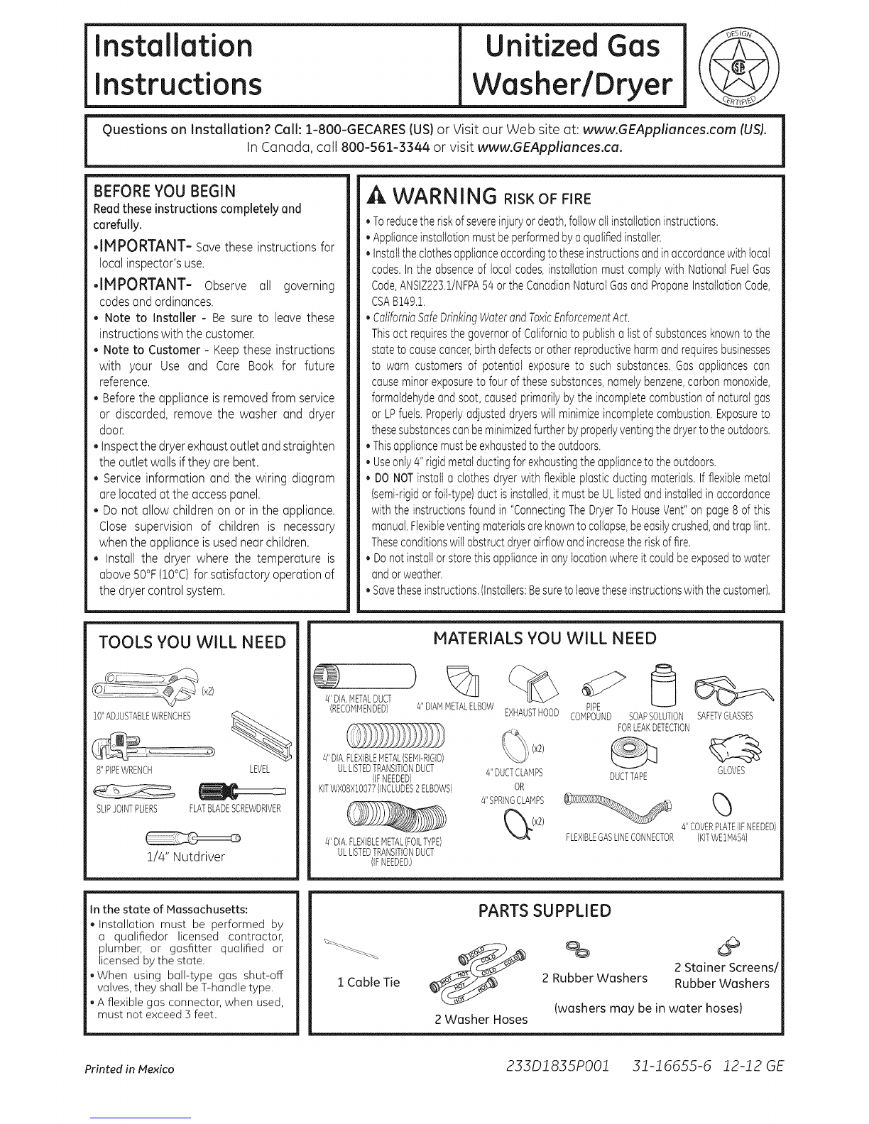
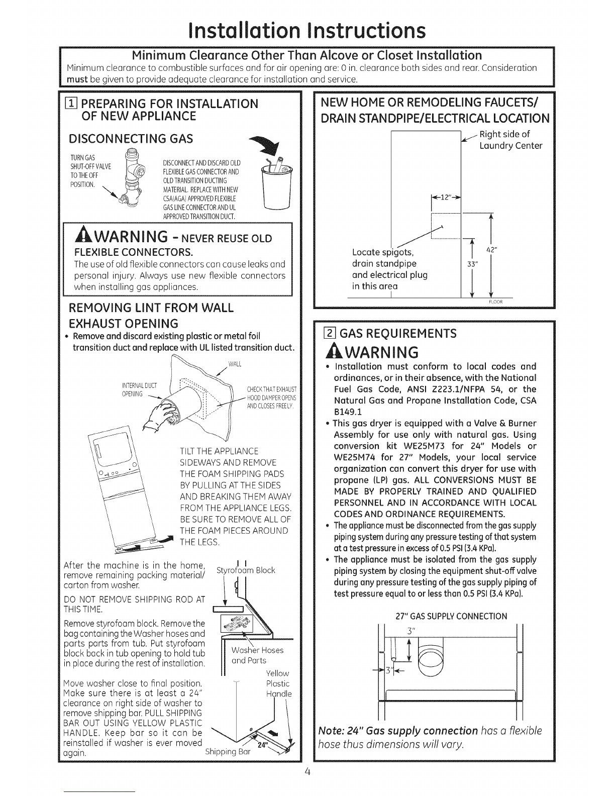
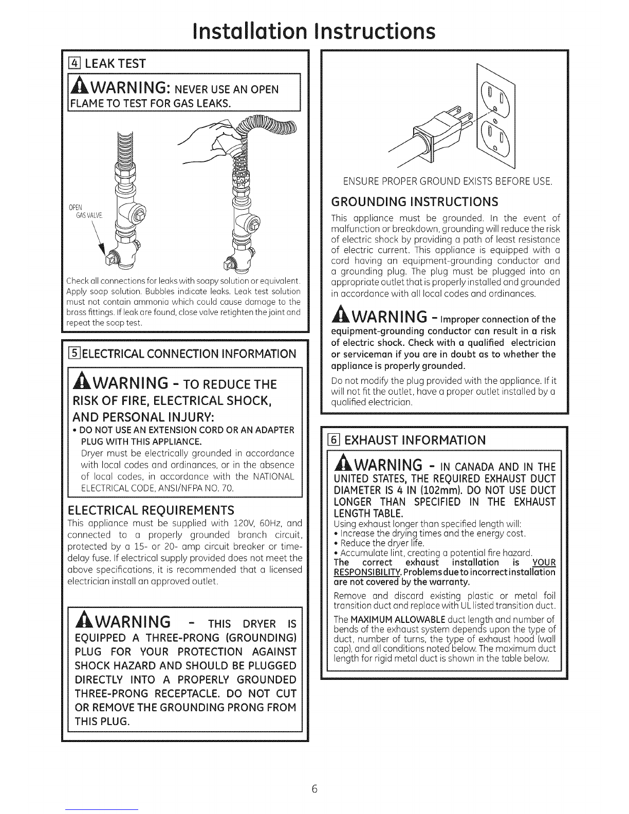
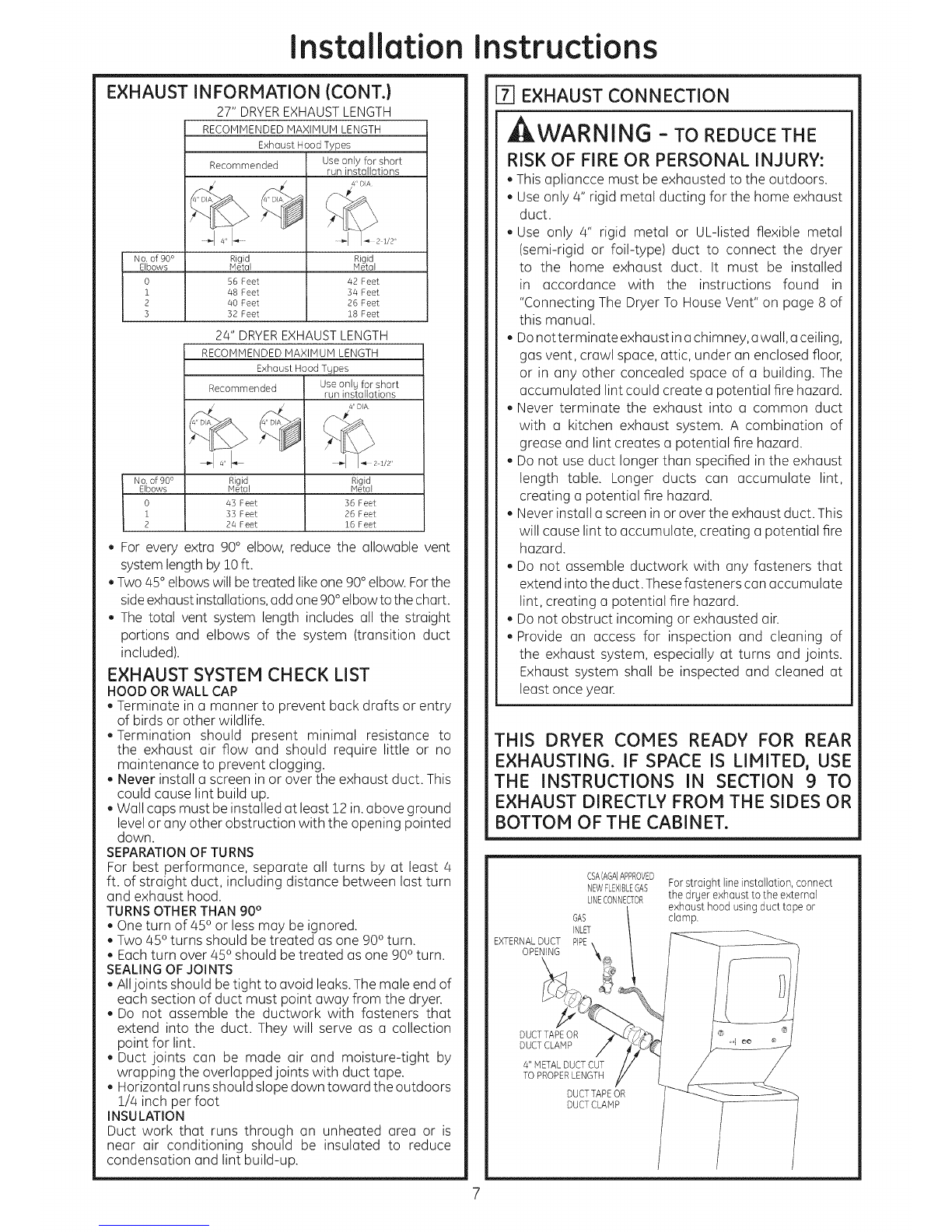
Installation instructions
Use only for short
run installations
No. of 900 Rigid Rigid
Elbows Metal Metal
O 56 Feet 42 Feet
i 48 Feet 34 Feet
2 40 Feet 26 Feet
3 32 Feet 18 Feet
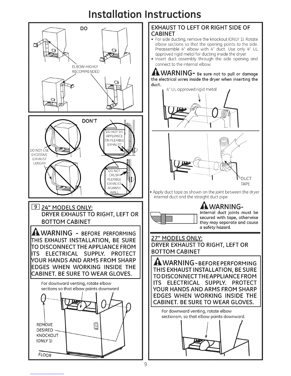
24" DRYEREXHAUSTLENGTH
RECOMMENDED MAXIMUM LENGTH
Exhaust Hood Types
Recommended Use only for short
run installations
No. of 900 Rigid Rigid
Elbows Metal Metal
O 45 Feet 56 Feet
i 53 Feet 26 Feet
2 24 Feet 16 Feet
EXHAUST INFORMATION (CONT.)
27" DRYEREXHAUSTLENGTH
RECOMMENDED MAXIMUM LENGTH
Exhaust Hood Types
Recommended
, For every extra 90° elbow, reduce the allowable vent
system length by 10ft.
, Two 45°elbows will be treated likeone 90°elbow. Forthe
sideexhaust installations,add one 90°elbow to the chart.
, The total vent system length includes all the straight
portions and elbows of the system (transition duct
included).
EXHAUST SYSTEM CHECK LIST
HOOD ORWALL CAP
, Terminate in a manner to prevent back drafts or entry
of birds or other wildlife.
, Termination should present minimal resistance to
the exhaust air flow and should require little or no
maintenance to prevent clogging.
, Never install u screen in or over the exhaust duct. This
could cause lint build up.
, Wall cups must be installed at least 12 in.above ground
level or any other obstruction with the opening pointed
down.
SEPARATIONOFTURNS
For best performance, separate all turns by at least 4
ft. of straight duct, including distance between lust turn
and exhaust hood.
TURNS OTHERTHAN 90°
, One turn of 450 or less may be ignored.
, Two 450 turns should be treated us one 900 turn.
, Each turn over 450 should be treated as one 900 turn.
SEALINGOFJOINTS
, Alljoints should be tight to avoid leaks.The mule end of
each section of duct must point away from the dryer.
, Do not assemble the ductwork with fasteners that
extend into the duct. They will serve as a collection
point for lint.
, Duct joints can be made air and moisture-tight by
wrapping the overlapped joints with duct tape.
, Horizontal runs should slope down toward the outdoors
1/4 inch per foot
INSULATION
Duct work that runs through an unheated urea or is
near air conditioning should be insulated to reduce
condensation and lint build-up.
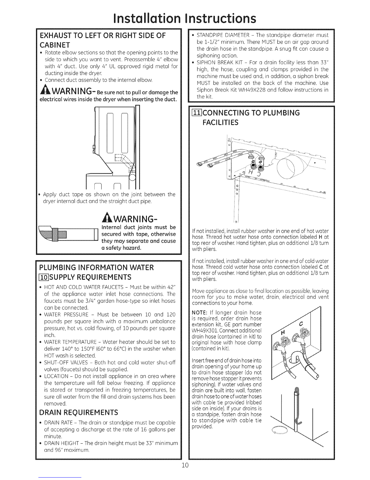
P-JEXHAUST CONNECTION
, WARNING - TO REDUCE THE
RISK OF FIRE OR PERSONAL INJURY:
, This apliancce must be exhausted to the outdoors.
, Use only 4" rigid metal ducting for the home exhaust
duct.
, Use only 4" rigid metal or UL-listed flexible metal
(semi-rigid or foil-type) duct to connect the dryer
to the home exhaust duct. It must be installed
in accordance with the instructions found in
"Connecting The Dryer To House Vent" on page 8 of
this manual.
, Donot terminate exhaust inu chimney, uwall, uceiling,
gas vent, crawl space, attic, under an enclosed floor,
or in any other concealed space of u building. The
accumulated lint could create a potential fire hazard.
, Never terminate the exhaust into a common duct
with u kitchen exhaust system. A combination of
grease and lint creates mpotential fire hazard.
, Do not use duct longer than specified in the exhaust
length table. Longer ducts can accumulate lint,
creating u potential fire hazard.
, Never install u screen in or over the exhaust duct. This
will cause lint to accumulate, creating mpotential fire
hazard.
, Do not assemble ductwork with any fasteners that
extend into the duct. Thesefasteners can accumulate
lint, creating mpotential fire hazard.
, Do not obstruct incoming or exhausted air.
, Provide an access for inspection and cleaning of
the exhaust system, especially at turns and joints.
Exhaust system shall be inspected and cleaned at
least once year.
THIS DRYER COMES READY FOR REAR
EXHAUSTING. IF SPACE IS LIMITED, USE
THE INSTRUCTIONS IN SECTION 9 TO
EXHAUST DIRECTLY FROM THE SIDES OR
BOTTOM OF THE CABINET.
EXTERNALDUCT
OPENING
CSA(AGA}APPROVED
NEWFLEXIBLEGAS For straight line installation, connect
LINECONNECTOR the drger exhaust to the external
exhaust hood using duct tape or
GAS clamp.
INLET
PIPE
DUCTTAPEOR
DUCTCLAMP
4" METALDUCTCUT
TO PROPERLENGTH
DUCTTAPEOR
DUCTCLAMP
7