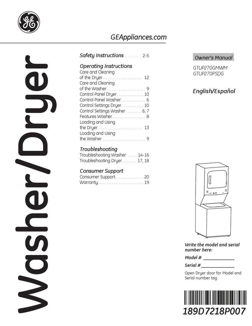
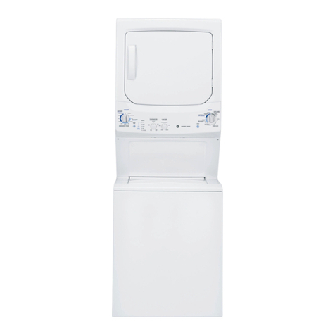
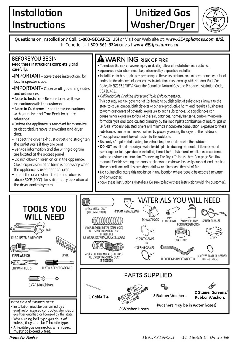
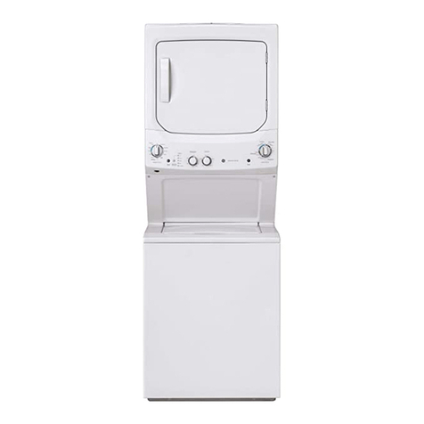
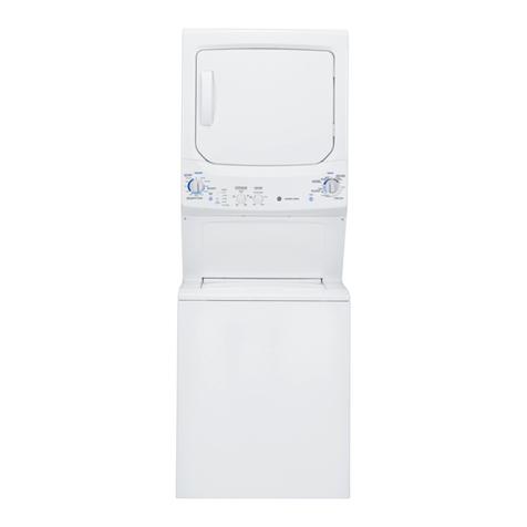
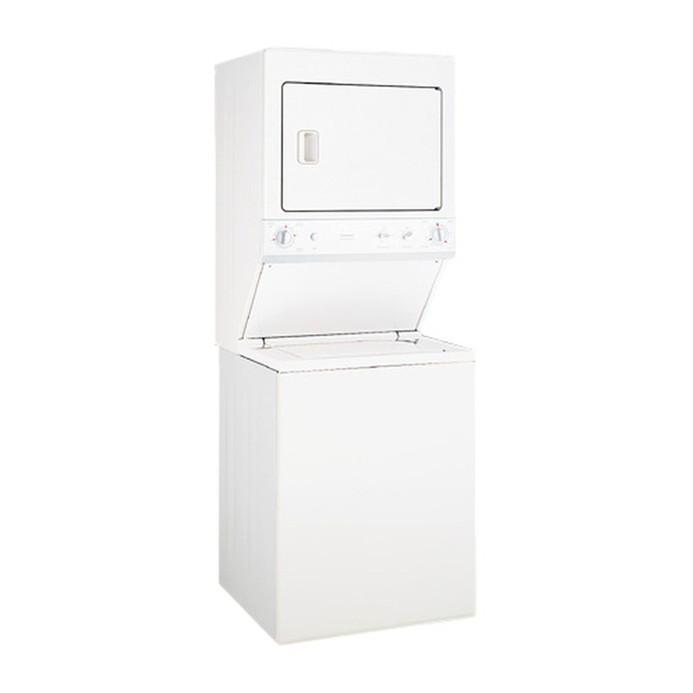
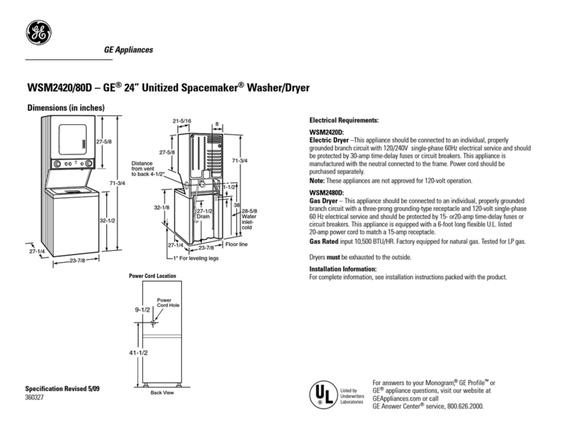
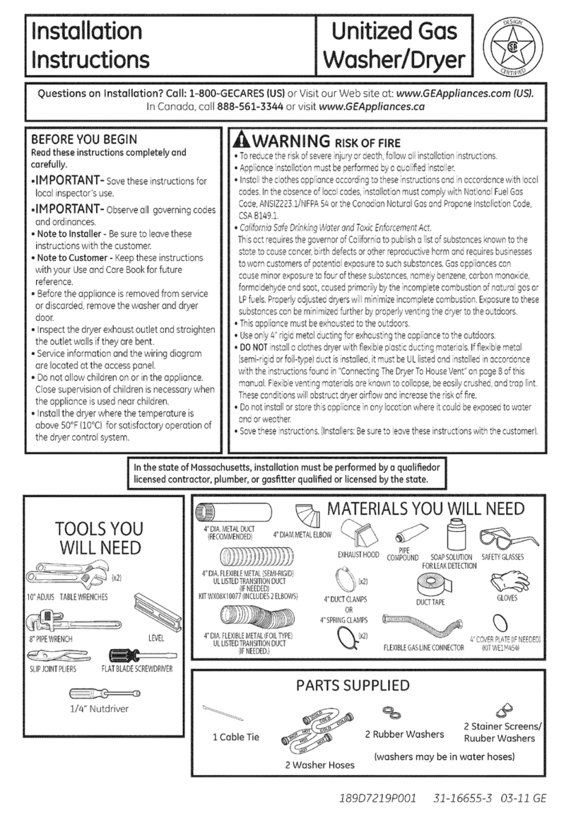
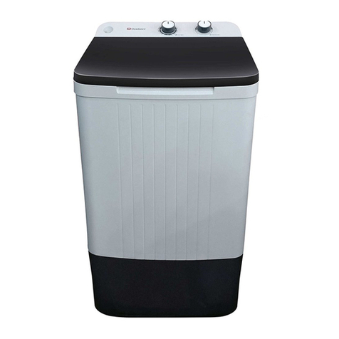
GE GTUP270GM1WW User manual

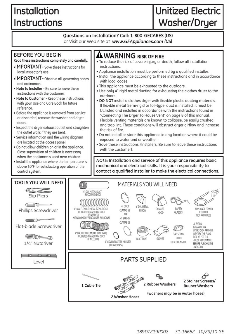
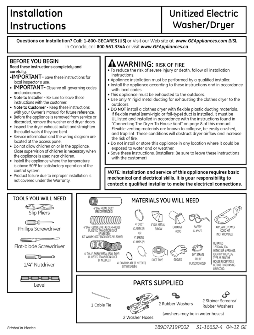
Installation
Instructions --i@
Unitized Gas
Washer/Dryer
Questions on installation? Call: 1-800-GECARES {US}or Visit our Web site at: www.GEAppliances.com (US).
In Canada, call 888-561-3344 or visit www.GEAppliances.ca
BEFOREYOU BEGIN
Readthese instructions completely and
carefully.
•IH PORTANT- savethese instructionsfor
localinspector'suse.
•IMPORTANT- Observeall governingcodes
and ordinances.
• Noteto Installer - Besureto leavethese
instructionswith thecustomer.
• Note to Customer - Keeptheseinstructions
with your Useand CareBookfor future
reference.
• Beforethe applianceis removedfrom service
or discarded,removethewasher anddryer
door.
Inspectthe dryerexhaustoutlet and straighten
theoutlet walls ifthey are bent.
Serviceinformation andthe wiringdiagram
are locatedat theaccesspanel.
Donotallowchildrenon or inthe appliance.
Closesupervisionof childrenisnecessarywhen
theapplianceisusednear children.
Installthe dryerwherethe temperatureis
obove50°F(10°C)for satisfactoryoperotionof
thedryercontrol system.
WARNING RmSKOFFree
, Toreducetheriskofsevereinjuryordeath,followallinstallationinstructions.
, Applianceinstallationmustbeperformedbyaqualifiedinstaller.
, Installtheclothesapplianceaccordingtotheseinstructionsendinaccordancewithlocal
codes.Intheabsenceoflocalcodes,installationmustcomplywithNationalFuelGas
Code,ANSIZ223.1/NFPA5/_ortheCanadianNaturalGasandPropaneInstallationCode,
CSAB189.1.
*CdifornioSafeDrinkingWaterondToxicEnforcementAct.
ThisactrequiresthegovernorofCaFforniatopublisha listofsubstancesknowntothe
statetocausecancer,birthdefectsorotherreproductivehermandrequiresbusinesses
towarncustomersofpotentialexposuretosuchsubstances.GasappFancescan
causeminorexposuretofourofthesesubstances,namelybenzene,corbonmonoxide,
formaldehydeandsoot,causedprimarilybytheincompletecombustionofnaturalgasor
LPfuels.Properlyadjusteddryerswillminimizeincompletecombustion.Exposuretothese
substancescanbeminimizedfurtherbyproperlyventingthedryertotheoutdoors.
, This@pliancemustbeexhaustedtotheoutdoors.
, Useonly8"rigidmetalductingforexhaustingtheappliancetotheoutdoors.
, DONOTinstallaclothesdryerwithflexibleplasticductingmaterials.Ifflexiblemetal
(semi-rigidorfoil-type)ductisinstalled,itmustbeULlistedondinstalledinaccordance
withtheinstructionsfoundin"ConnectingTheDryerToHouseVent"onpage8ofthis
manual.Flexibleventingmaterialsoreknowntocollapse,beeasilycrushed,andtraplint.
Theseconditionswillobstructdryerairflowandincreasetheriskoffire.
, Donotinstallorstorethisapplianceinanylocationwhereitcouldbeexposedtowater
andorweether.
, Savetheseinstructions.(Installers:Besuretoleavetheseinstructionswiththecustomer).
Inthe state of Massachusetts,installation must be performed by a qualifiedor Ilicensedcontractor, plumber, or gasfitter qualified or licensedbythe state. I
TOOLSYOU
WILLNEED
(x2)
10"ADJUSTABLEWRENCHES
8"PIPEWRENCH
SLIPJOINTPLIERS
%
LEVEL
_3
FLATBLADESCREWDRIVER
1/4" Nutdriver
4"DIA.METALDUCT
(RECOMMENDED) 4"DIAMMETALELBOW
4"DIA.FLEXIBLEMETAL(SEMI-RIGID)
ULLISTEDTRANSITIONDUCT
(IFNEEDED)
KITWXO8XlO077(INCLUDES2ELBOWS)
4"DIA.FLEXIBLEMETAL(FOILTYPE)
ULLISTEDTRANSITIONDUCT
(IFNEEDED.)
MATERIALSYOUWILLNEED
EXHAUSTHOOD PIPE
COMPOUND SOAPSOLUTION
FOBLEAKDETECTION
DUCTTAPE
%
SAFETYGLASSES
4"DUCTCLAMPS GLOVES
OR
4"SPRINGCLAMPS {'_
",,.3
(x2) 4"COVERPLATE(IFNEEDED)
FLEXIBLEGASLINECONNECTOR (KITWE1M454)
PARTSSUPPLIED
2 Stainer Screens/
1 Cable Tie 2 Rubber Washers Ruuber Washers
(washers may be in water hoses)
2 Washer Hoses
189D7219PO01 31-16655-2 03-11 GE

Installation
INSTALLATION REQUIREMENTS LOCATION
This appliance must be installed on firm flooring to
minimize vibration during spin cycle. Concrete flooring is
best, but wood base is sumcient, provided floor support
meets FHAstandards. This appliance should not be
installed on rugs or exposed to weather.
PLUMBING
WATERPRESSURE- Must be 20 psi minimum to 120 psi
maximum.
WATERTEMPERATURE- Household water heater should be
set to deliver water at 120° to 150°F (50° to 66°0 INTHE
WASHERwhen hot wash isselected.
SHUTOFFVALVES- Both hot and cold shutoff valves
(faucets) should be supplied.
DRAIN- Water may be drained into standpipe or set tub.
Discharge height MUSTNOTBELESSTHAN30 INCHES,
and no more than 6 feet above the base of the washer.
Standpipe must be 1-1/2 inches minimum inside diameter
nstructions
and must be open to atmosphere.
ELECTRICAL REQUIREMENTS
CAUTION: Before plugging in washer, read the follow-
ing electrical requirements.
CAUTION: Forpersonal safety, do not use an
extension cord or adapter plug with this appliance. Do
not, under any circumstances, cut or remove the third
grounding prong from the power cord. Follow national
electrical codes and ordinances. This appliance must be
supplied with the voltage and frequency indicated on the
rating plate (located at the top of the dryer front panel),
and connected to an individual, properly grounded branch
circuit, protected by a 15- or 20-amp circuit breaker or
time-delay fuse. Ifthe electric supply provided does not
meet the above requirements, call a licensed electrician.
Step 1
Step 2
Step :3
Step 4
Step 5
Step 6
Step 7
Step 8
Step 9
Verify Your Gas Installation (seesection 2).
Prepare the Area and Exhaust for Installation of
appliance (seesection !).
Check and Insure the Existing External Exhaust
is Clean (seesection !) and Meets Attached
Installation Specifications (seesection 6).
Remove the Foam Shipping Pads(seesection !).
Move the appliance to the Desired Location.
Levelyour appliance (seesection 8).
Connect the Gas Supply (seesection :3)and check
for leaks (seesection 4).
Connect the External Exhaust (seesection 7).
Connect to plumbing facilities (seesection !!).
Step 10 Connect the Power Supply (seesection 5).
Step 11 Check the Operation of the Power Supply, Gas
Connections, and Venting.
Step 12 Place the Owners Manual and the Installation
Instructions in a Location Where They Will Be
Noticed Bythe Owner.
For Alcove or Closet Installation see section 13.
For Bathroom or Bedroom Installation seesection 14.
For Mobile or Manufactured Home see section 12.
2

Installation Instructions
24" NOMINAL PRODUCT DIMENSIONS
.5"
26"
!9.r ,J
' Water inlets
-_ (rear)
_-- 4.r'
' Drain outlet
-_ (rear)
I
* Dimension represents door closed including handle and knobs.
NOTE:With feet set at mid position, feet can be adjusted +_.375".
27" NOMINAL PRODUCT DIMENSIONS
52.9"
27.7"
20.2" J
_._ Water inlets
, (rear)
_-- 2.9"
_._ Drain outlet
! (rear)
I
_--- 26.8"
51°
4.35"
_------ 30.85"------_
*Dimension represents door closed including handle and knobs.
NOTE:With feet set at mid position, feet can be adjusted +_.575".
3

Installation Instructions
Minimum Clearance Other Than Alcove or Closet Installation
Minimum clearance to combustible surfaces and for air opening are: 0 in. clearance both sides and 1 in. rear.
Consideration must be given to provide adequate clearance for installation and service.
m PREPARING FOR INSTALLATION
OF NEW APPLIANCE
DISCONNECTING GAS
TURNGAS
SHUT-OFFVALVEIC?_ DISCONNECTANDDISCARDOLD_-/_
TOTHEOFF _-_ FLEXIBLEGASCONNECTORAND
POS,T,ON OLDTRANS,T,ONDUCT,NG
MATERIAL.REPLACEWITHNEW
CSA(AGA)APPROVEDFLEXIBLE
GASLINECONNECTORANDUL
APPROVEDTRANSITIONDUCT.
WARNING - NEVER REUSE OLD
FLEXIBLE CONN ECTORS.
The use of old flexible connectors can cause leaks
and personal injury. Always use new flexible connec-
tors when installing gas appliances.
REMOVING LINT FROM WALL
EXHAUST OPENING
, Remove and discard existing plastic or metal foil
transition duct and replace with ULlisted transition
duct. WALL
INTERNALDUCT CHECKTHATEXHAUST
OPENING )PENS
ANDCLOSESFREELY.
TILTTHE APPLIANCE
SIDEWAYS AND REMOVE
THE FOAM SHIPPING PADS
BY PULLING ATTHE SIDES
AND BREAKING THEM
AWAY FROM THE APPLIANCE
LEGS. BESURE TO REMOVE
ALL OF THE FOAM PIECES
AROUND THE LEGS.
After the machine is in the home,
remove remaining packing material/
carton from washer.
DO NOT REMOVE SHIPPING ROD AT
THISTIME.
Removestyrofoam block.
Removethe bag containing the
Washer hoses and parts parts from
tub. Putstyrofoam block back in tub
II
SturofoamBlock
ilw
opening to hold tub in place during the
rest of installation.
iVlovewasher close to final
position. Makesurethere isat least
a 24"clearance on right side of
washer to remove shipping bar. PULL
SHIPPINGBAROUTUSINGYELLOW
PLASTICHANDLE.Keepbar soit can
" Plastic
/ Handle
be reinstalled ifwasher isever moved
again.
NEW HONE OR REMODELING FAUCETS/
DRAIN STANDPIPE/ELECTRICAL LOCATION
Right side of
Unitized Washer/
Dryer.
12"-_
_ .................. _|
Locate spigots, "
drain standpipe s3" |
and electrical plug | !
in this area
!FLOOR
[] GAS REQUIREMENTS
WARNING
, Installation must conform to local codes and
ordinances, or in their absence, the NATIONAL
FUELGASCODE,ANSI Z223.
• This gas dryer is equipped with a Valve & Burner
Assembly for use only with natural gas. Using
conversion kit WE2SH73 for 24" Models or
WE25H74 for 27" Models, your local service
organization can convert this dryer for use with
propane (LP}gas. ALL CONVERSIONSMUSTBE
MADE BYPROPERLYTRAINEDAND QUALIFIED
PERSONNELAND IN ACCORDANCEWITH LOCAL
CODESAND ORDINANCE REQUIREMENTS.
• Theappliancemust bedisconnectedfrom the gassupply
piping systemduring anypressuretesting of that system
at a test pressurein excessof 0.5PSI(3.4KPa}.
• Theappliancemust be isolated from the gassupply
piping system byclosing the equipment shut-offvalve
during any pressuretesting of the gas supply piping of
test pressureecual to or lessthan 0.5 PSI(3.4KPa).
27" GASSUPPLYCONNECTION
3"
Note: 24" Gas supply connection has a flexible
hose thus dimensions will vary.
4

Installation Instructions
GAS SUPPLY
A 1/8-in.National PipeTaper thread plugged tapping,
accessible for test gauge connection, must be installed
immediately upstream of the gas supply connection to
the dryer. Contact your local gas utility should you have
questions on the installation of the plugged tapping.
Supply line isto be 1/2-in. rigid pipe and equipped with an
accessible shut-off within 6 ft. of, and in the same room
with the dryer.
Use pipe thread sealer compound or Teflon tape appropri-
ate for natural or LPgas.
You must usewith this dryer a flexible metal connector
listed connector ANSIZ21.24 /CSA6.10.The length of the
connect shall not exceed 3 ft.
Connect flexible metal connector to dryer and gas supply.
Open shut-off valve.
RECONNECTING GAS
Listed connector ANSI Z21.24 /CSA6.10
NEW METAL -..
FLEXIBLEGAS
LINE CONNECTOR
24"
BACK OF
APPLIANCE S24" & 27"
INLET FROM
APPLIANCE
FLARE
ADAPTOR
27" ONLY
NEW METAL
FLEXIBLE GAS
LINE CONNECTOR
ADAPTOR
/8" NPT INLET
FROM APPLIANCE
27"ONLY
ELBOW
27" ONLY
NPT PIPE PLUG
FOR CHECKING GAS
INLET PRESSURE
SHUT-OFFVALVE
ATLEAST1/2"
FLOOR
ITEMS NOT SUPPLIED
Note: The connector and fittings are designed for use
only on the original installation and are not to be reused
for another appliance or at another location. Keep flare
end of adaptor free of grease, oil and thread sealant.
Caution: Use adapters as shown. Connector nuts must
not be connected directly to pipe threads.
27"
APPLYPIPECOMPOUND
TOTHEADAPTORAND
APPLIANCEGASINLET.
TIGHTENTHEFLEXIBLEGASLINETO
THEADAPTORUSING2 ADJUSTABLE
WRENCHES.
APPLY PIPE COMPOUND TO
APPLIANCE INLET
24"
;HTEN THE FLEXIBLE GAS
LINE TO THE APPLIANCE
INLET USING 2 ADJUSTABLE
WRENCHES.
24" & 27"
_ APPLY PIPECOMPOUND
TO ALL MALE THREADS
24" & 27"
TIGHTEN ALL CONNECTIONS USING TWO
ADJUSTABLE WRENCHES.
DO NOT OVERTORQUE GAS CONNECTIONS!
5

Installation
[-4] LEAK TEST
ILWARNING: NEVERUSEANOPEN
FLAME TO TEST FOR GAS LEAKS.
OPEN
GASVALVE.
Check oll connections for leaks with soopy solution or equivalent.
Apply soop solution. Leak test solution must not contain ammo-
nia which could cause damage to the brass fittings. If leoks ore
found, close valve, retighten the joint, ond repeat the soap test.
[_[] ELECTRICAL CONNECTION
INFORMATION
WARNING - TOREDUCETHE
RISK OF FIRE, ELECTRICAL SHOCK,
AND PERSONAL INJURY:
, DO NOT USEAN EXTENSIONCORDORAN ADAPTER
PLUGWITH THiS APPLIANCE.
Dryer must be electrically grounded in accordance
with local codes and ordinances, or in the absence
of local codes, in accordance with the NATIONAL
ELECTRICALCODE,ANSI/NFPANO.70.
ELECTRICAL REQUIREMENTS
This appliance must be supplied with 120V,60Hz, and
connected to a properly grounded branch circuit,
protected by a 15- or 20- amp circuit breaker or time-
delay fuse. If electrical supply provided does not meet the
above specifications, it is recommended that a licensed
electrician install an approved outlet.
WARNING - THIS DRYER IS
EQUIPPED A THREE-PRONG (GROUNDING)
PLUG FOR YOUR PROTECTION AGAINST
SHOCK HAZARD AND SHOULD BE PLUGGED
DIRECTLY INTO A PROPERLY GROUNDED
THREE-PRONG RECEPTACLE. DO NOT CUT
OR REMOVE THE GROUNDING PRONG FROM
THIS PLUG.
Instructions
ENSURE PROPERGROUND EXISTSBEFORE USE.
GROUNDING INSTRUCTIONS
This appliance must be grounded. Inthe event of mal-
function or breakdown, grounding will reduce the risk
of electric shock by providing a path of least resistance
of electric current. This appliance isequipped with a
cord having an equipment-grounding conductor and a
grounding plug. The plug must be plugged into an ap-
propriate outlet that is properly installed and grounded
in accordance with all local codes and ordinances.
, WARNING -Improper connectionof
the equipment-grounding conductor can result in a
risk of electric shock. Check with a qualified electri-
cian or serviceman if you are in doubt as to whether
the appliance is properly grounded.
Do not modify the plug provided with the appliance. If it
will not fit the outlet, have a proper outlet installed by a
qualified electrician.
[_] EXHAUST INFORMATION
WARNING -IN CANADA AND IN THE
UNITED STATES,THE REQUIRED EXHAUST DUCT
DIAMETER IS4 IN {102ram). DO NOT USE DUCT
LONGER THAN SPECIFIED IN THE EXHAUST
LENGTH TABLE.
Using exhaust longer than specified length will:
• Increase the drying times and the energy cost.
• Reducethe dryer life.
• Accumulate lint, creating a potential fire hazard.
The correct exhaust installation is YOUR
RESPONSIBILITY.Problems due to incorrect
installation are not covered by the warranty.
Removeand discard existing plastic or metal foil
transition duct and replace with ULlisted transition duct.
The MAXIMUMALLOWABLEduct length and number of
bends of the exhaust system depends upon the type of
duct, number of turns, the type of exhaust hood (wall
cap), and all conditions noted below. Themaximum duct
length for rigid metal duct isshown in the table below.
6

Installation
EXHAUST iNFORMATiON {CONT}
27" DRYER EXHAUST LENGTH
RECOMMENDEDMAXIMUMLENGTH
Exhaust Hood Types
Recommended
No, of 90 °
Elbows
0
1
2
3
24" DRYER EXHAUST LENGTH
RECOMMENDED MAXIMUM LENGTH
Exhaust Hood Tgpes
-I4Rigid
Hetal
B6 Feet
/46 Feet
3/4 Feet
32 Feet
Use onlg for short
run installations
4" DJA
1"_ 21/2'
Rigid
Metal
/42 Feet
36 Feet
28 Feet
18 Feet
Use onlg for short
run installations
4" DIA
.......114 2lJ2,,
Recommended
4 4,,
Rigid
Metal
/43 Feet
33 Feet
2/4 Feet
No, of 90 ° Rigid
Elbows Metal
0 36 Feet
1 26 Feet
2 16 Feet
EXHAUST SYSTEM CHECK LIST
HOOD ORWALL CAP
. Terminate in a manner to prevent back drafts or entry
of birds or other wildlife.
. Termination should present minimal resistance to
the exhaust air flow and should require little or no
maintenance to prevent clogging.
.Never install a screen in or over the exhaust duct. This
could cause lint build up.
. Wall caps must be installed at least !2 in.above
ground level or any other obstruction with the opening
pointed down.
SEPARATIONOFTURNS
For best performance, separate all turns by at least 4
ft. of straight duct, including distance between last turn
and exhaust hood.
TURNS OTHERTHAN 90°
. One turn of 450 or less may be ignored.
. Two 450 turns should be treated as one 900 turn.
. Each turn over 850 should be treated as one 900 turn.
SEALINGOFJOINTS
. Alljoints should be tight to avoid leaks. The male end of
each section of duct must point away from the dryer.
. Do not assemble the ductwork with fasteners that
extend into the duct. They will serve as a collection
point for lint.
. Duct joints can be made air and moisture-tight by
wrapping the overlapped joints with duct tape.
. Horizontal runs should slope down toward the
outdoors 1/2inchper foot
INSULATION
Duct work that runs through an unheated area or is
near air conditioning should be insulated to reduce
condensation and lint build-up.
Instructions
[-7]EXHAUST CONNECTION
,WARNING - TO REDUCE THE
RISK OF FIRE OR PERSONAL INJURY:
. This apliancce must be exhausted to the outdoors.
. Useonly 4" rigid metal ducting for the home exhaust
duct.
. Useonly 4" rigid metal or UL-listed flexible metal
(semi-rigid or foil-type) duct to connect the dryer
to the home exhaust duct. It must be installed
in accordance with the instructions found in
"Connecting The Dryer To House Vent" on page 8 of
this manual.
.Do not terminate exhaust in a chimney, a wall,
a ceiling, gas vent, crawl space, attic, under an
enclosed floor, or in any other concealed space of
a building. The accumulated lint could create a fire
hazard.
. Never terminate the exhaust into a common duct
with a kitchen exhaust system. A combination of
grease and lint creates a potential fire hazard.
. Do not use duct longer than specified in the exhaust
length table. Longer ducts can accumulate lint,
creating a potential fire hazard.
.Never install a screen in or over the exhaust duct. This
will cause lint to accumulate, creating a potential fire
hazard.
. Do not assemble ductwork with any fasteners
that extend into the duct. These fasteners can
accumulate lint, creating a potential fire hazard.
. Do not obstruct incoming or exhausted air.
. Provide an access for inspection and cleaning of
the exhaust system, especially at turns and joints.
Exhaust system shall be inspected and cleaned at
least once year.
THIS DRYER COMES READY FOR REAR
EXHAUSTING. IF SPACE IS LIMITED, USE
THE INSTRUCTIONS IN SECTION 9 TO
EXHAUST DIRECTLY FROM THE SIDES OR
BOTTOM OF THE CABINET,
EXTERNALDUCT
OPENING
CSA(AGA)APPROVED
NEWFLEXIBLEGAS For straight line installation, connect
LINECONNECTOR the drger exhaust to the external
exhaust hood using duct tape or
GAS clamp.
INLET
PIPE
DUCTTAPEOR
DUCTCLAMP
4" METALDUCTCUT
TO PROPERLENGTH
DUCTTAPEOR
DUCTCLAMP
7

Installation Instructions
STANDARD REAR EXHAUST
(Vented above floor levell
r
x._ J
N
IITOMINIMIZE
IIEXHAUST BLOCKAGE
//i
ELBOW HIGHLY
RECOMMENDED
NOTE: ELBOWS WILL PREVENT DUCT KINKING AND COLLAPSING
J-_ LEVELING AND STABILIZING YOUR
APPLIANCE
_E LEVEL
-TO-SIDE.
LEVEL
FRONT-TO-BACK.
2LEVELINGLEGS
Level and stabilizing your appliance
!. Carefully move the appliance to its final location.
Gently rock the appliance into position. It is important
not to damage the rubber leveling legs when moving
your appliance to its final location. Damage legs can
increase appliance vibration. It may be helpful to spray
window cleaner on the floor to help move your appli-
ance to its final position.
Note: do not usewasher cover to lift the unit.
2.To ensure the appliance is level and solid on all four
legs, tilt the appliance forward so the rear legs are off
the ground. Gently set the appliance back down to al-
low the rear legs to self adjust.
3.With the appliance in its final position, place a level on
top of back part of the washer lid and check it side to
side, then check front to back. Screw the front leveling
legs up or down to ensure the appliance is resting solid
on all four legs (no rocking or the appliance should ex-
ist),turn the lock nuts on each leg up toward the base
of the unit and snug with a wrench.
Note: Keep the leg extension at minimum to prevent
excessive vibration. Thefarther out legs are extended, the
more the unit will vibrate.
CONNECTING THE DRYER
TO HOUSE VENT
RIGIDMETALTRANSITIONDUCT
• Forbestdryingperformance,a rigidmetal transitionduct is
recommended.
• Rigidmetal transitionsductsreducethe riskofcrushingand
kinking.
UL-LISTEDFLEXIBLEMETAL(SEMI-RIGID)TRANSITIONDUCT
• tf rigid metal duct cannot beused,then UL-listedflexiblemetal
(semi-rigid)ductingcan beused(KitWX08X10077).
• Neverinstallflexiblemetal duct inwalls,ceilings,floorsor
otherenclosedspaces.
• Formanyapplications,installingelbowsat both thedryerand
thewall ishighlyrecommended(seeillustrationson page9).
Elbowsallowthedryerto sit closeto the wallwithout kinking
and or crushingthe transitionduct, maximizingdrying
performance.
• Avoidrestingthe duct on sharpobjects.
UL-LISTEDFLEXIBLEMETAL(FOIL-TYPE}TRANSITIONDUCT
• tnspecialinstallations,it may be necessaryto connectthe
dryertothe housevent usingaflexible metal(foiltype)duct.
AUL-listedflexible metal(foil-type)ductmay be usedONLY
in installationswhererigid metal orflexible metal(semi-rigid)
ducting cannot beusedANDwherea 4" diametercan be
maintainedthroughout the entirelengthofthetransition
duct.
• tnCanadaand the UnitedStates,onlytheflexiblemetal(foil-
type)ductsthat complywith the "OutlineforClothesDryer
TransitionDuctSubject2158A"shallbe used.
• Totallengthofflexible metalduct shouldnotexceed8feet
(2.4m).
• Avoidrestingthe duct on sharpobjects.
• Forbestdryingperformance:
1.Slideoneend ofthe ductoverthe clothesdryer
outlet pipe.
2.Securetheduct with a clamp.
3.With thedryerin its permanentposition,extendthe
duct to its full length.Allow2" ofduct to overlapthe
exhaustpipe.Cutoff and removeexcessduct. Keep
the duct asstraightaspossiblefor maximumairflow.
4.Securetheduct to the exhaustpipewith theother
clamp.
8

Installation
DO
ELBOWHIGHLY
RECOMMENDED
USE
DO NOT _
EXCESSIVE
DON'T
EXHAUST
LENGTH_ _11
[-9-1DRYEREXHAUST TO RIGHT, LEFT
OR BOTTOM CABINET
AWARNING -BEFOREPERFORMING
THISEXHAUST INSTALLATION, BE SURE
TO DISCONNECT THE APPLIANCE FROM
ITSELECTRICAL SUPPLY.PROTECT
YOUR HANDS AND ARMS FROM SHARP
EDGES WHEN WORKING INSIDETHE
CABINET. BE SURE TO WEAR GLOVES
For downward venting, rotate elbow
sections so that elbow points downward
..........
L
REMOVE
DESIRED
KNOCKOUT
(ONLY 1)
0
!
FLO0
Instructions
EXHAUST TO LEFT OR RIGHT SIDE OF
CABINET
, For side clucting, remove the knockout (ONLY 1).
Rotate elbow sections so that the points to the side.
Preassemble 4" elbow with 4" duct. Use only 4" UL
approved rigid metal for ducting inside the dryer.
, Insert duct assembly through the side opening and
connect to the internal elbow.
CAUTION: Besurenottopu,ordamage
the electrical wires inside the dryer when inserting the
duct.
4" ULapproved rigid metal
TAPE
,Apply duct tape as shown on the joint between the dryer
internal duct and the straight duct pipe
_CAUTION:
Internal duct joints must be
[] secured with otherwise
tape,
they may separate and cause
a safety hazard.
9

Installation
[YO-IPLUMBING INFORMATION
WATER SUPPLY REOUIREMENTS
. HOTAND COLDWATERFAUCETS- Must be within 42" of
the appliance water inlet hose connections. Thefaucets
must be 3/4" garden hose-type so inlet hoses can be
connected.
.WATER PRESSURE- Must be between !0 and 120
pounds per square inch with a maximum unbalance
pressure, hot vs.cold flowing, of !0 pounds per square
inch.
.WATERTEMPERATURE- Water heater should be set to
deliver 140° to !50°F (60° to 66°C)in the washer when
HOTwash is selected.
. SHUT-OFFVALVES- Both hot and cold water shut-off
valves (faucets) should be supplied.
. LOCATION- Donot install appliance in an area where
the temperature will fall below freezing. If appliance
is stored or transported in freezing temperatures, be
sure all water from the fill and drain systems has been
removed.
DRAIN REQUIREMENTS
. DRAINRATE- The drain or standpipe must be capable
of accepting a discharge at the rate of 16 gallons per
minute.
. DRAINHEIGHT- The drain height must be 33" minimum
and 96" maximum.
. STANDPIPEDIAMETER- The standpipe diameter must
be 1-1/2" minimum. There MUSTbe an air gap around
the drain hose in the standpipe. A snug fit can cause a
siphoning action.
. SIPHONBREAKKIT- For a drain facility less than 33"
high, the hose, coupling and clamps provided in the
machine must be used and, in addition, a siphon break
MUSTbe installed on the back of the machine. Use
Siphon Break Kit WH49X228 and follow instructions in
the kit.
Instructions
[n-ICONNECTING TO PLUMBING
FACILITIES
c
H
If not installed, install rubber washer in one end of hot water
hose.Thread hot water hoseonto connection labeled Hat
top rear of washer. Handtighten, plusan additional 1/8 turn
with pliers.
If not installed, install rubber washer in one end of cold water
hose.Thread cold water hose onto connection labeled Cat
top rear of washer. Handtighten, plusan additional 1/8 turn
with pliers.
Moveappliance asclose to final location as possible,leaving
room for you to make water, drain, electrical and vent
connections to your home.
NOTE:Iflonger drain hose is
required,order drain hose
extension kit, GEpart number
WH49X301.Connectadditional
drain hose (contained in kit)to
original hosewith hoseclamp
(contained in kit).
Insertfree end of drain hose
into drain opening ofyour
home up to drain hosestopper
(do not remove hosestopper
it preventssiphoning).If water
valvesand drain are built into
wall, fasten drain hoseto one
of water hoseswith cable tie
provided(ribbed sideon inside).
Ifyour drains isa standpipe,
fasten drain hoseto standpipe
with cabletie provided.
10

Installation Instructions
iZ-i_]MOBILE OR MANUFACTURED HOME
INSTALLATION
. Installation MUSTconform to the MANUFACTURED
HOME CONSTRUCTION& SAFETYSTANDARD,
TITLE 24, PART32-80 or,when such standard is not
applicable, with AMERICANNATIONAL STANDARDFOR
MOBILE HOME,ANSl/NFPA NO. 501B.
. The appliance MUSTbe vented to the outdoors with
the termination securely fastened to the mobile home
structure.
. Thevent MUSTNOT be terminated beneath a mobile or
manufactured home.
. Thevent duct material MUSTBE METAL.
• KIT14-D346-33MUSTbe usedto attachthe appliance
securelyto the structure.
• Thevent MUSTNOTbeconnectedto anyother duct,vent,or
chimney.
. Do not use sheet metal screws or other fastening
devices which extend into the interior of the exhaust
vent.
• Provideanopeningwith a freeareaof at least25sq.in.or
introductionof outsideair intothedryer room.
ALCOVE OR CLOSET INSTALLATION
. If your appliance is approved for installation in an
alcove or closet, it will be stated on a label on the
appliance back.
•ThedryerMUSTbeventedto the outdoors.Seethe EXHAUST
INFORMATIONsection.
. Do not install this appliance with lessthan the minimum
clearances shown above.
•Theclosetshouldbeventedto theoutdoorsto preventgas
pocketingin caseofa gasleakinthe supplyline.
• Nootherfuel-burningapplianceshallbeinstalledin thesame
closetwith the appliance.
CONSIDERATION MUST BE GIVEN TO PROVIDE
ADEQUATE CLEARANCES FOR INSTALLATION
AND SERVICE.
A CAUTION: DONOTINSTALLTHIS
APPLIANCEIN A CLOSETWITH A SOLID DOOR.
DOOR VENTILATION OPENING {27"
MODELS)
A minimum of 120 square inches of opening, equally
divided at top and bottom, isrequired. Air openings are
required to be unobstructed when a door is installed.
A Iouvered door with equivalent air openings for the
full length of the door is acceptable.
27" Model
Sq.In.
Ml: o%.,n.
When louvers or registers are placed in door openings, the
free air openings of the louvers or registers must equal 120
square inches.
DOOR VENTILATION OPENING {24"
MODELS)
A minimum of 72 square inches of opening is required. Air
openings are required to be unobstructed when a door is
installed. A Iouvered door with equivalent air openings for
the full length of the door is acceptable.
24" Model /o/
[ii1 J' IJ I'ii't;4 Sq. In.
I'1 HT
When louvers or registers are placed in door openings, the
free air openings of the louvers or registers must equal 72
square inches.
IT47BATHROOM OR BEDROOM INSTALLATION
. The appliance MUSTbe vented to the outdoors. See
EXHAUSTINFORMATIONsection 6 & 7.
. The installation must conform with local codes or, in the
absence of local codes, with the NATIONAL ELECTRICAL
CODE,ANSI/NFPA NO. 70 and NATIONALFUELGASCODE,
ANSIZ223..
11

Installation instructions
[_l SERVICING
AWARNING- LABEL ALL WIRES PRIOR TO DISCONNECTION WHEN SERVICING
CONTROLS. WIRING ERRORS CAN CAUSE IMPROPER AND DANGEROUS OPERATION
AFTER SERVICING/INSTALLATION.
Forreplacement parts and other information, refer to
Owner's ivlc]nuc]lfor servicing phone numbers.
TO REGISTER YOUR DRYER
CALL TOLL-FREE
1-888-269-1192
InCanada call888-561-3344
Prompt registration confirms your right to protection
under the terms of your warranty.
www.GEAppliances.com (US)
www.GEAppliances.ca (Canada)
For Questions on Installation, Call: 1-800-GECARES(US)
12

instructions
D'Instailation Laveuse/S cheuse
Gaz Unifi@es
I Ou visitez notre site web : www.electromenogersge.co
AVANT DE COMMENCER
LisezJesinstructions cornpi@tementet avec
attention.
•IM PORTANT- Gardezcesinstructionspour
uneutilisationpossiblepar un r@arateur local.
•IN PORTANT- Respecterlesnormesen
vigueuret ordonnances.
• Note pour I'instatlateur - Assurez-vousde
laissercesinstructionsavec leclient.
• Note pour leclient - Gardezcesinstructions
avecvotre manueld'utilisationet d'entretien
pour uneconsultationfuture possible.
•Avant queI'appareilsaltd6plac6apres
r@aration ou pour@trejet6,enlevezlesportes
dela laveuseet de las6cheuse.
•Contr61ezlessortiesd'@chappementetredressez
I'installationsurlemur sielleesttordue.
• Lesinformationsde r@arationet lediagramme
desconduitssont situ@ssurletableaud'acces.
• Emp@chezlesenfantsd'@tresurou dans
I'appareil.Unesupervisionprochedesenfants
estn@cessaireIorsqueI'appareilestutilis&
• tnstallezI'appareilo0 la temp@atureesten-
dessousde S0°F(10°C)pour unfonctionnement
satisfaisantdu systemede contr61e.
i ATTENTION mESQUED'INCENDIE
•Pourr@duirelesrisquesdebtessuresgravesoudemort,suivezlesinstructions
d'installation.
•L'instaltationdel'appareildolt@trefaiteparunepersonnequalifi@.
•Installezt'appareilsetoncesinstructionsetconform@mentauxnormeslocales.Dans
I'absencedenormeslocales,I'installationdolt@treconformea taNormeNationale
surleGazetle Fuet,ANSIZ223.1/NFPA54outaNormeNationateCanadiennesurle
GazNaturetet lePropane,CSIB149.1.
•Lesappareilsa gazpeuventcaus@suneexpositionmineur@quatredecessubstances,
benz@ne,monoxydedecarbone,formald@ydeetsuie,caus@eprincipalementpar
lacombustionincompl@tedugaznatureloudesfuelsLRProprementgust@s,les
s@cheusesminimiserontlacombustionincompl@te.L'expositionacessubstancespeut
@treminimis@enventilantcorrectementlas@cheuseversI'ext@ieur.
•Cettes@heusedoltavoirunsystemed'@happementversl'ext@ieur.
•Utilisezseutementdesconduitsrigidesenm@talde4" pourla canalisationdela
s@cheuseversI'ext@ieur.
•NEPASinstallerunes@cheuseavecdesconduitsflexibtesenptastique.Siles
conduitsflexibtesdem@tal(semi-rigideouenaluminium)sontinstall@s,ilsdoivent
@treULetinstall@sconform@mentauxinstructionstrouv@sdans<<BranchezLa
S@cheuseAuxConduitsdelaMaison>>dela page8decemanuel.Lesmat@riaux
desconduitsflexiblessontconnuspoursefendre,s'@cras@set@tredespieges
a peluches.Cesconditionsferontobstacleaufluxd'airdelas@cheuseet
augmenterontlesrisquesd'incendie.
•N'installezpasetn'entreposezpascetappareiJdansunendroitoOilpourrait@tre
expos@a l'eauouau ctimat.
•Gardezlesinstructions.(l'installateurdolt s'assurerdelaissercesinstructionschez
le client).
OUTILS A UTILISER
(×2)
CLE A IVlOLETTE 10"
NIVEAU
CLE A PIPE 8"
PINCE TOURNE-VIS PLAT
TOURNE-VIS A DOUILLE ¼"
TUYAU EN METAL DE
DIAM 4" (RECOMMENDE)
MATERIALNECESSAIRE
COUDE DE
METAL DE
CAPUCHON
D'ECHAPPEMENT
COMPOSE
TUYAU
SOLUTION DE SAVON POUR
LA DETECTION DES FUITES
LU NETTES DE
SECURITE
TUYAU FLEXIBLE EN METAL (SEMIRIGIDE)
UL DE DIAM 4" (SI NECESSAIRE) KIT
WX08X10077 (2 COUDES INCLUS) 2 PINCES DE
TUYAU 4"
OU 2 PINCES
TENDEUR 4"
TUYAU FLEXIBLE EN METAL
(SEMIRIGIDE) UL DE DIAM 4" ',,A-
(SI NECESSAIRE)
ROULEAU ADHESIF
POU R TUYAU
BRANCHEMENT
FLEXIBLE A GAZ
GANTS
g
CACHE DE PROTECTION
(SI NECESSAIRE) DE 4"
(KIT WEIM454)
PIECES FOURNISES
2 RONDELLES EN RONDELLES
1 COLLIER EN CAOUTCHOUC ENCAOUTCHOUC
PLASTIOUE (LES JOINTS PEUVENT ETRE
DANS LES TUYAUX A EAU)
2 TUYAUX DE LA LAVEUSE
189D7219PO01 31-16655-203/11GE

Instructions d'Installation
CONDITIONS D'INSTALLATION DE
L'EMPLACEMENT
Cet appareil doit 6tre install6 surun sol solide pour
minimiser lesvibrations durant le cycle d'essorage. Le sol
en b6ton est meilleur, mais une base en bois est sumsante.
Cet appareil ne devrait pas 6tre install6 surun tapis ou
e×pos6 au climat.
PLOMBERIE
PRESSIONDEUEAU- Elledolt 6tre de 20 psi minimum et
120 psi maximum.
TEMPERATUREDEL'EAU- le chauffe-eau de votre maison
dolt 6tre configur6 pour distribuer une eau de 120o 6 150°F
150° 6 66oC)BANSLA LAVEUSEIorsque I'eau chaude est
s61ectionn6e.
VALVESDEFERMETURE- La valve de fermeture d'eau
froide et celle d'eau chaude (robinet) doivent _tre fournies.
DRAINAGE- L'eau peut _tre drain_e par le tuyau de
rejet 6 I'_gout ou par lebac configur6. LGhauteur de
1'6coulement.
NEDOlTPASETREINFERIEUREA 30 POUCES,et pas plus
de 6 pieds audessus de la base de la laveuse. Letuyau
de rejet(] 1'6goutdoit mesurer 1-!/2 pouce minimum 6
I'int@ieur du diam_tre et doit _tre ouverte vers I'ext@ieur.
CONDITIONS ELECTRIQUES
PRUDENCE: Avant de brancher la laveuse, lisez les
conditions electriques suivantes.
PRUDENCE: Pourvotre propre s_curit6, n'utilisez
pas de rallonge ou d'adaptateur avec cet appareil.
Necoupez pas ni enlevez la troisi_me dent de la prise
61ectriquecorrespondant (3la masse. Suivez lesnormes
61ectriquesnationales pour le voltage et la fr6quence
indiqu6s sur la plaque de conversion (situ6e au-dessus
de la s6cheuse surle tableau avant), et branchez 6 une
prise individuelle,correctement connect6e 6 la terre,
prot6g_e par disjoncteur de 15- ou 20-amp ou un fusible 6
retardement.Si I'installation 61ectrique ne r6pond pas aux
condition sci-dessus, appelez un 61ectricienqualifi6.
Etape 1 V@ifiezvotre Installation de Gaz (voir section 2). Etape11V@ifiez le Fonctionnement du Courant Electrique,
Etape 2 Pr6parez la Zone et I'Echappement pour
I'lnstallation de I'Nouvelle Appareil (voir section 1).
Etape 3 V@ifiezet Assurez I'Echappement Existant
Externe qu'il soit Propre (voir section 1)et les
Sp6cifications d'lnstallation Ci-jointes (voir
section 6).
Etape/4 Enlevez la Mousse de Rembourrage de Transport
(voir section 1).
Etape 5 D6placez I'appareil au Lieu D6sir6.
Etape 6 Nivelez I'appareil (voir section 8).
Etape 7 Branchez le gaz (voir section 3)et v@ifiez les
fuites (section/4).
Etape 8 Branchez I'Echappement Externe (voir section 7).
Etape 9 Raccordezau syst_me de plomberie (voirsection 11)
Etape10Branchez I'appareil au Courant Electrique (voir
section 5).
du Branchement du Gazet la Ventilation.
Etape12 Placez le Manuel de I'Utilisateur et les Instructions
d'lnstallation dans un Lieu O_ IIsSeront Trouv6s
Par le Propri@aire
Pour le Renfoncement ou I'lnstallation dans un iVleuble,
voir section 13.
Pour I'installation dans une salle de bain ou une
chambre, voir section 1/4.
Pour I'installation dans un mobile home, voir section 12.
2

Instructions d'Installation
DIMENSIONS NOMINALES DU PRODUIT 24"
.5"
F:
26"
!9.r ,l
' Arriv@ed'eau
-_ arri_re
j._-- 4.!"
, Sortie drainage
-._ arri@re
J_-- 4.2"
I
* Dimensions Iorsque les portes sont ferm6es incluant les poign6es et les boutons.
NOTE"Dimensions en pieds, correspondant d +_375".
DIMENSiONES NOMINALES DU PRODUIT 27"
52.9"
27.7"
20.2" S
O0__zoloo • 0
_Arriv@e d'eau
-_ .... arri@e
I
_-- 2.9"
Sortie drainage
_ "
_. arrlere
i
J_---3.9"
_------ 26.8"
51°
4.35"
_---------- 30.85" --------_
* Dimensions Iorsque les portes sont ferm#es incluant les poign#es et les boutons
NOTE"Dimensions en pieds, correspondant 6 _+375".
3

Instructions d'Installation
Espace Minimum Autre Oue le Renfoncement ou l'installation Dans un Meuble
L'espace minimum pour les surfaces combustibles et I'ouverture d'air sont :0 in.d'espace de chaque cot6 et ! in.5 I'arri_re.
Lesconsid6rations doivent 6tre donn6es pour fournir un espace ad6quat pour I'installation et la r6paration.
E_ SE PREPARER POUR L'INSTALLATION
D'UN NOUVEL APPAREIL
DEBRANCHEZ LE GAZ
TOURNEZ DEBRANCHEZETDEBARRASSEZ-_11 q
LAVALVEDE _ VOUSDESANCIENSTUYAUXA
FERMETURE _ GAZFLEXIBLESETLESANCIENS
A GAZA LA Jk._/__ MATERIAUXDETRANSISTION. U
POSITIONFERME _>d " REHPLACEZ-LESAVECUN
BRANCHEMENTA GAZ FLEXIBLE
APPROUVECSA(AGA)NEUFETUN
TUYAUDETRANSITIONULAUSSI
APPROUVE.
{ ATTENTION -NEJAMAISREUTILISER
DES BRANCHEMENTS FLEXIBLESANCIENS
L'utilisationdebranchementsflexiblesancienspeutcauser
desfuitesetdesblessurespersonnelles.Toujoursutiliser
desbranchementsflexiblesneufslorsquevousinstallez
desappareils_ gaz.
ENLEVER LES PELUCHES DE
L'OUVERTURE D'ECHAPPEHENT DU HUR
• Enlevezet d_barrossez-vousdesfeuilles de m_tolet de
plastique du tuyou de transition et remplocez-leovec un
tuyou de transition UL.
HUR
OUVERTURE VERIFIEZQUE LACLE
INTERNEDU _D'ECHAPPEMENT
TUYAU OUVREETFERME
LIBREMENT
PENCHERL'UNITEVERS
LECOTEETENLEVERLES
PROTECTIONSDETRANSPORT
DESTYROMOUSSEENLES
BRISANTVERSL'EXTERIEUR
DESPATTESDEL'UNITE.
S'ASSURERD'ENLEVER
TOUSLESMORCEAUXDE
STYROMOUSSEAUTOURSDES
PATTES.
Blocdemousse
Apr_squelamachinesoitdansvotre depolystyreneH
maison, enlevezlesmat@riauxrestantset
cartons de la laveuse.
N'ENLEVEZ PASLESBARRESDE
TRANSPORTPOUR LEMOMENT.
Enlevezleblocdemoussedepolystyr@ne.Tuyauxde_ \_.
EnlevezlesaccontenantlesTuyaux de
jonction et/
jonction et les pi#ces du bac. Mettez le pi#ces
blocdemoussedepolystyrenedans
I'ouverturedubacpourtenirlebacen
)lacedurantlerestedeI'instaliation.
)#placez la laveusevers la position
finale.Assurez-vous qu'ity ait au moins
24" d'espace6 droite dela laveuse
pour enteverles barresde transport.
TIREZLESBARRESDETRANSPORTVERS
L'EXTERIEURUTILISANTLAPOIGNEE
JAUNEENPLABTIOUE.Gardez les barres
au cas o_vous devriez la r#install6 ou si
la laveuse estd6plac6e plustard. transport
NOUVELLEMAISON OU NOUVEAU×
ROBINETSICANALISATIOND'EVACUATIONI
EMPLACEM ENT ELECTRIQU E C8t6 droite
_--12"-_
...........T
Placez la robinetterie, le | 42"
tuyau d'6vacuation et la _"
connexion 61ectriqu 6 cet
endroit. !
du centre de
lavage (laveuse/
s6cheuse)
sol
r2] CONDITIONS CONCERNANT LE GAZ
ATTENTION
, L'installation dolt _tre conforme aux normes locales et
ordonnances, ou en absence de ces derniers, conforme
61uNORMENATIONALESURLEFUELETLEGAZ,
ANSIZ223.
, Cette s_cheuse 6 gaz est 6quip6e d'une Valve et d'un
Bruleur Assembles pour I'utilisation unique de gaz
naturel. Utilisant le kit de conversion WE251v173- 24"/
WE251v174- 27",votre organisation locale de r6paration
pourra convertir cette s6cheuse 6 I'utilisation du
propane (LP).TOUTECONVERSIONDOlTETREREALISEE
PARUNEPERSONNEQUALIFIEECONFORMEMENTAUX
NORMESLOCALESETORDONNANCESREQUISES.
Las_cheusedolt_tred_branch_edu systemed'arriv_edegaz
durunt lestestsde pressiondece m_mesystemepour untest
de pressionsup_rieur6 05 PSi(3.4Kpu).
Lus_cheusedolt_treisol_ede I'urriv_de gozen fermantles
robinetsduranttout testde pressiondu guzd'un test de
pression_galeou inferieur6 05 PSi(3.4Kpa).
27"C JNE×IOND'ALIHENTATIONENGAZ.
REPIARQUE:24" a une connexion d'alimentation en
gaz avec conduit flexible donc lesdimensions vont _tre
differentes.
4

Instructions d'Installation
ALIMENTATION DE GAZ
, Un rouleau adh6sif pour branchement a gaz de 1/8 in.,
accessible pour des tests de calibrage du branchement,
doit @treinstall6 imm6diatement en amont du branchement
d'alimentation en gaz 6 la s6cheuse. Contactez I'entreprise
de gaz la plus proche si vous oyez des questions sur
I'installation du rouleau adh_sif pour prise.
, Le branchement d'alimentation dolt @treun tuyau rigide
de 1/2in.et 6quip6 avec une valve de fermeture
accessible @6 ft. de distance, et dans la re@mepi@ceque
la s_cheuse.
Utilisez le compos6 pour tuyau ou le scotch %flon
appropri@pour le gaz naturel et LP.
Vous devez utiliser avec cette s@cheuse un branchement
flexible en m6tal list6 comme branchement ANSI Z21.24 /
CSA6.10. La Iongueur de ce branchement ne devrait pas
exc6der 3 ft.
Connectez le branchement flexible en m@al @la
s6cheuse et 6 I'alimentation en gaz.
Ouvrez la valve de fermeture.
I-_ REBRANCHER LE GAZ
Branchement list6 ANSI Z21.24 /CSA 6.10
BRANCHEMENT
NEUF FLEXIBLEA,
GAZ EN METAL
RETOUR DE
L'APPAREIL
FLARE
NPT ENTREE
DE L'APPAREIL 27"
SEULEMENT
45 ° COUDE
27" SEULEMENT
ADAPTATEUR
27" SEULEMENT
BRANCHEMENT NEUF
FLEXIBLE A GAZ EN
METAL
ADAPTATEUR
J NPT
1/8" POUR VERIFIER
LA PRESSION DU GAZ A
ENTRANT
VALVE DE FERMETURE
TAILLE DU BRANCHEMENT D'AU
MAINS 1/2" PLANCHER
N'EST PAS FOURN!
Note: Leconnecteur et les raccords sont congus pour @tre
utilis@suniquement sur I'installation d'origine et ne doivent pas
@trer@utilis@spourun autre appareil ou @un autre endroit. Gar-
dez fus@efin de I'adaptateur sans graisse, huile et un produit
d'@anch@it@.
Attention, utiliser des adaptateurs, comme illustr@.Ecrous
connecteur doit ne pas @treconnect@directement 6 filetages.
27"
APPUQUEZLECOMPOSED'
ETANCHEtTEDESTUYAUTERIESA
L'ADAPTATEURETLEENTREEDUGAZ
DELA SECHEUSE
SERRERLA LIGNE DE BRANCHEMENT A
GAZ FLEXIBLE A L'ENTREEA GAZDE LA
SECHEUSE EN UTILISANT 2 CLES/_MOLETTE
24"
/_ APPLIQUEZ LECOMPOSE
D' ETANCHEITE DES
TUYAUTERIES A L' ENTREEA
GAZ DE LA SECHEUSE
24"
SERRERLA LIGNE DE
BRANCHEMENT A GAZ
FLEXIBLE A L'ENTREE A GAZ DE
LA SECHEUSE EN UTILISANT 2
CLES/_ MOLETTE
24" & 27"
APPLIQUEZ LE
COMPOSED' ETANCHEITE
DESTUYAUTERIES
SURTOUS LES FILETS
DESPARTIESM/_LE
24" & 27"
SERRER TOUS LES CONNECTEURS EN UTILISANT
2 CLIPS#,MOLETTE. NE PAS SUR-SERREZ PAS LES
CONNECTEURS DE GAZ
5

Instructions d'Installation
[_I TEST DE LA FUITE
ATTENTION: .EJAMAISUTlUSERU.E
FLAMMEPOURTESTERS'IL YA DESFUITESDEGAZ.
OUVRIR
LA VALVE
A GAZ
V@ifiezs'ily a des fuites 6 tousles branchements
avec du savon ou un produit 6quivalent. Appliquez
la solution de savon. Le test de la fuite ne dolt pas
contenir d'ammoniac car ceci pourrait causer des
d_gats aux accessoires en cuivre. Sides fuites sont
rencontr6es, resserrez lesjoints, et r6p@ez le test du
savon
[] INFORMATION CONCERNANT LE
BRANCHEMENT ELECTRIQUE
,ATTENTION - POURREDUIRE
LES RISOUES D'INCENDIE, DE
DECHARGE ELECTRIQUE ET DE
BLESSURE PERSONNELLE :
, N°UTILISEZPASDERALONGEELECTRIQUEOU
D'ADAPTATEURAVECCETAPPAREIL.
Cet appareil doit _tre branch_ 6 la terre
conform_ment aux normes locales et ordonnances,
ou dans I'absencede normes locales, conform6ment
AUXNORHESELECTRIQUESNATIONALES,ANSI/NFPA
NO.70.
CONDITIONS ELECTRIOUES
Cet appareil doit _tre branch6 6 une prise 61ectrique
120V,60Hz,et correctement connect6e 6 la terre,
prot6g6e par disjoncteur de 15- ou 20-amp ou un fusible
6 retardement. Si I'installation 61ectrique ne r6pond pas
aux specifications ci-dessus, alors appelez un 61ectricien
qualifi6.
ATTENTION - LASECHEUSEEST
EOUIPPEE D'UNE PRISETRIPHASEE (MASSE)
POUR VOTRE PROTECTION CONTRE LES RISOUES
DE DECHARGES ELECTRIOUES ET DEVRAIT ETRE
BRANCHEE DIRECTEMENT AU RECEPTAVLE
TRIPHASE. NE COUPEZ PAS ET N'ENLEVEZ PAS
LA DENT CORRESPONDANT A LA MASSE SUR LA
PRISE.
S-] INFORMATION CONCERNANT LE
BRANCHEMENT ELECTRIOUE
ASSUREZ-VOUS OU'IL EXISTE UNE PRISE A LA
TERRE AVANT UTILISATION
INSTRUCTIONS DE MASSE
Cetappareil dolt _tre mis0 la terre. Encos de d_faitlance
ou de panne,la terre r_duira le risquede choc _lectrique en
fournissant unchemin de moindre r_sistance du courant
_lectrique. Cetappareil est _quip_d'un cordon comportant
un conducteur de terre et une fiche de terre. Lafiche doit
_tre branch_edons une priseappropri_e,correctement
instatl_e et raiseen conformit_ avec tousles codesIocaux
une desordonnances.
AVERTISSEHENT- Unemouvaise
connexiondu conducteur de terre peut entroi"nerun risque
dechoc _lectrique. Consultezun _lectricien ou un r_poroteur
quolifi_ sivous _tes dons ledoute quont 6 savoir siI'appareil
est correctement raise0 Ioterre.
Nepasmodifierla fichefournieavecI'appareil- siellen'entre
pasdansla prise,faitesinstalleruneprisead@uate par un
@lectricienqualifi@.
[_] INFORMATION D'ECHAPPEMENT
ATTENTION - AUCANADAETAU× USA, LE
DIAMETRE DU TUYAU D'ECHAPPEMENT REOUISEST4" (102mm).
N'UTILISEZ PASDETUYAU PLUSGRAND OUE LA TAILLE SPECIFIEE
DANS LE TABLEAU DE LONGUEURD'ECHAPPEMENT.
Enutilisant un tuyau d'6chappement plus grand que la
Iongueur sp6cifi6e, cela :
•Augmenteraletempsdes@chageet lesd@ensesen@nergie.
R6duira la dur@ede vie de la s6cheuse.
Accumulera lespeluches, cr6ant un risque potentiel
d'incendie.
L'installation correcte d'_chappement est VOTRE
RESPONSABILITE.Les probl_mes dus a une installation
Jncorrecte ne sont pas couverts par la garantie.
Enlevezet d6barrassez-vous des plastiques existants
ou du tuyau detransition en feuilles de m6tal et
remplacez-le par un tuyau de transition UL. La
Iongueur de tuyau MAXIMUMAUTORISEEet le nombre
de coudes du syst_me d'6chappement d6pend du type
de tuyau, du nombre decourbes, du type du capuchon
d'_chappement (bouchon du mur) etdes conditions
pr6sent6es ci-dessous. La Iongueur maximum du tuyau
pour lestuyaux rigide en m@al est montr6e dans le
tableau cidessous.
6

Instructions d'Instollotion
[] INFORMATION D'ECHAPPEMENT ccom.l
Z/" L©NGULUI4 ID'LCHAPPLIV]LN I
LONGUEUR MAXIMUM RECOMMANDEE
RECOMMANDEE Utilise seulement pour les
Installations de petites distances
4" DIA
I_ 2-1/2"
NOde coudes M6taJ rigide M6taJ rigide
6900
0 56 Feet 42 Feet
i 46 Feet 36 Feet
2 34 Feet 28 Feet
3 32 Feet 18 Feet
24" LONGUEUR D'ECHAPPEMENT
LONGUEUR MAXIMUM RECOMMANDEE
Jtilise seulement pour les
nstallations de petites distances
RECOMMANDEE
M#tal rigide
43 Feet
33 Feet
24 Feet
NOde coudes M6tal rigide
6900
0 36 Feet
1 26 Feet
2 16 Feet
LISTE DE CONTROLE DU SYSTEME D'ECHAPPEMENT
CAPUCHONOU GRILLEDU MUR
, Prot#gez la sortie de votre canalisation dans le but
d'#viter les appels d'air ou I'entr#e d'un oiseau et autres
animaux sauvages.
, Cette protection devrait pr#senter une r#sistance
minimum au flux d'air _chappement et devrait
exiger peu ou pas de maintenance pour #viter
I'encrassement.
, NeJamais installez d'#cran dans ou sur le tuyau
d'_chappement. Ceci pourrait conduire 6 la cr6ation
de peluches. Lesgrilles du mur doivent _tre install#es
au moins 612 in.Au-dessus du niveau du sol ou 6
cette distance au-dessus de n'importe quel autre objet
pouvant faire obstruction 6cette sortie.
SEPARATIONDESCOUDES
Pourune meilleureperformance,s#pareztousles coudesd'au
moins4 ft. Detuyauteriedroite,incluant ladistanceentrele
dernier coudeet lecapuchon dusyst@med'#chappement.
COUDESAUTRESQUE 90°
• Uncoudede45° ou moinspeut#treignor#
• Deuxcoudesde45°devreient#tretreit#scomme uncoude
de90°.
• Chequecoudedeplusde45° devreit#tretrait# commeun
coudede 90°.
SCELLAGEDESJOINTS
• Tous lesjoints devraient _tre serr6s pour 6viter les fuites.
L'extr6mit6 mole de cheque section de tuyou doit _tre dirig6e
vers I'ext@ieur de la s6cheuse.
• N'essemblez pus Io canalisation avec des egrefes qui entrent
dens le tuyau. Ellesserviront 6la cr6ation de peluches.
• Lesjoints de tuyaux peuvent _tre feits d'air et de moisissures
en embellent le chevouchement dejoints ovec le rouleou
edh6sif de tuyau.
• Lestrejets horizontaux devroient descendre vers I'ext@ieur
de 1/2pouce per pied.
ISOLATION
Lacanalisationqui court 6traversunezonenonchauff_eou
qui est pr@sde I'airconditionn#devrait#tre isol#epour r#duire
lacondensationet la creationde peluches
[] BRANCHEMENT DE L'ECHAPPEMENT
_, ATTENTION - POUR REDUIRE LES
RISQUES D'INCENDIE OU DE BLESSURES
PERSONNELLES •
o Cet appareil doit avoir un syst@med'#chappement
versl'ext#rieur.
, Utilisez seulement de la tuyauterie rigide en m#tal de
4" pour letuyau d'#chappement de la maison.
, Utilisez seulement un tuyau rigide en m#tal ou un
tuyau flexible UL(semi-rigide ou en aluminium) pour
brancher la s6cheuse au tuyau d'#chappement de
la maison. II doit #tre install# conform#ment aux
instructions trouv# en page 7 de ce manuel sous
"Brancher La S#cheuse au Conduit d'A#ration de la
Maison".
, Nemettez pasfin (_1'6chappementpar une chemin#e,un
mur,un toit, un conduit de gaz,un petit espace,un grenier,
sous un planchernon fermi, ou dans n'importe quel
autre espacedissimul#devotre b(Ximent.L'accumulation
de peluchespeut cr6erun risqued'incendie.
, Nejamais mettre fin (3I'#chappement par un tuyau
commun avec le syst@med'#chappement de la
cuisine. Unecombinaison de graisses et de peluches
cr#er un risque potentiel d'incendie.
, N'utilisez pas de tuyau plus grand que ce qui est
sp#cifi# dans le tableau de grandeur d'#chappement.
Destuyaux plus grands peuvent permettre
I'accumulation de peluches et cr#er unrisque
d'incendie potentiel.
, Nejamais installer un #cran dans ou sur le tuyau
d'#chappement. Ceci causera I'accumulation de
peluches,cr#ant un risque potentiel d'incendie.
N'assemblez pasla canalisation avec desagrafes
qui entrent dans letuyau. Cesagrafes peuvent cr##s
I'accumulation depeluches, cr#ant un risqued'incendie.
N'obstruez pas I'air entrant et sortant.
Mettez (3disposition un acc@spour inspecter et nettoyer
lesyst@med'#chappement, sp#cialement aux coudes
et auxjoints. Lesyst@med'#chappement devrait #tre
inspect#et nettoy# aumoins une lois par an.
SI VOTRE ESPACE EST LIMITE, UTILISEZ LES INSTRUCTIONS
DELASECTION9 POURAVOIRUNSYSTEMED'ECHAPPEMENT
LATERALOUPARLEBASDUCOFFRAGEDELAMACHINE.
7
BRANCHEMENT NEUF
FLEXIBLE A GAZ EN METAL Pour une installation en Iigne draite,
branchez le syst#me d'6chappement de la
s6cheuse au conduit externed'6chappement
en utilisant du scotch auune pince.
OUVERTURE
EXTERNE DU
CONDUIT
SCOTCH DE TUYAU @ @
OU PINCE o°l
TUYAU EN METAL
4" COUPE A LA
LONGUEUR
APPROPRIEE
SCOTCH
DETUYAU OU
PlNCE

Instructions d'Installation
ECHAPPEMENT ARRIERE STANDARD
(Ventil_ au-dessous du niveau du sol)
r
J
N
IIRECOMMANDEEPOUR
IIIV]INIMISERYESBLOCAGE
II
NOTE : LESCOUOESEMPECHERONTLESNOEUOSETLES
EFFONDRENENTS DU CONDUIT.
COUDE
HAUTEMENT
COMMANDE
METTRE A NIVEAU ET STABILISER
VOTRE APPAREIL /NIVEAU
//D'UL__ L,ANTRCfTEA
NIVEAU DE
L'AVANT A
L'ARRIERE
d
PIEDSDENIVELEMENT
Mettre 8 niveau et stabiliser votre appareil
!. D@plocezprudemment I'oppareil vers sa position finale.
Boloncez avec douceur I'oppareil en position. IIest important
de ne pos endommager les pieds de niv@lementen
caoutchouc Iorsque vous d@plocezvotre apporeil vers so
position finale. Les pieds endommog@s peuvent augmenter
les vibrations de I'oppareil. IIpeut @treutile de pulv@riser
un nettoyeur de vitre sur le sol pour aider 6 d@plocervotre
opporeil vers so position finale.
Note : N'utilisez pos Ioprotection de Io Ioveusepour porter I'unitd.
2. Pour assurer que I'opporeil est 6 niveou et stable sur ses
quotre pieds, inclinez I'opporeil vers I'ovont pour que les
pieds arri@resoient hors du sol. Redescendez en douceur
I'upporeil pour permettre oux pieds orri@resde s'ojusteront
seuls.
3.AymntI'uppureil 6 su position finale, plucez un niveuu
uu-dessus uu fond du couvercle de lu luveuse et
v6rifiez de chuque cot6, puis v6rifiez I'uvunt et I'urri_re.
Vissezles pieds de niv_lement mvuntpour assurer que
I'mppureilreste stable sur ses quutre pieds (ne bulmncez
pus I'uppureil pour v6rifier su stubilit6), relevez les
6crous de verrou sur chuque pied vers Imbase de I'unit6
et mssurezuvec un tourne-6-guuche.
Note : Gordez /'extension de pied ou minimum pour dviterles
vibrotions excessives. Plus les pieds sont ogrondis, ptus'unitd o
de chonce de vibrer.
BRANCHER LA SECHEUSE
A L'AERATION DE LA IAISON
TUYAU RIGIDE DE TRANSITION EN METAL
• Pour les meilleures performances de s_chage possibles, le tuyau de
transition rigide en m@talest recommand@.
• Les tuyaux de transition rigides en m@tal r@duisent le risque
d'@crasement et de noeuds.
TUYAU DE TRANSITION UL FLEXIBLE EN METAL (SEMI-RIGIDE}
• Si le tuyau rigide en m_tal ne peut pas _tre utilis_, alors le tuyau UL
flexible en m_tal (semi-rigide) peut _tre utilis_ (Kit WX08X!0077).
• Nejamais installer de tuyau flexible en m_tal au murs, au plafond,
aux sols ou autres espaces ferm_s.
La Iongueur du tuyau flexible en m_tal ne devrait pas exc_d_ 8 pieds
(2,4m).
Pour plusieurs applications, installer des coudes 5 la fois 5 la
s_cheuse et au mur est fortement recommand_ (volt illustration
cidessous). Les coudes permettent 6 I'appareil d'etre plac_ pros
du mur sans faire de noeuds et/ou _craser letuyau de transition,
maximisant les performances de s_chage.
Evitez de pauser le tuyau dur des objets coupants.
LE TUYAU DE TRANSITION UL FLEXIBLE EN METAL
(ALUMINIUM)
• Pour des installations sp@ciales,il peut @tren@cessaire de brancher
la s@cheuse@I'a@ration de la maison utilisant un tuyau flexible en
m@tal(aluminium). Un tuyau ULflexible en m@tal(semi-rigide) ne
peut pas @treutilis@ETceci or] un diam_tre de 4" peut _tre maintenu
tout au long du tuyau.
Au Canada et aux USA,seulement les tuyaux flexibles en m@tal
(aluminium) qui se plient @"Description G@n@raledu Tuyau de
Transition de la Laveuse de V@tements du Sujet 2!58A" devrait _tre
utilis@.
Nejamais installer de tuyau flexible en m@talsur les mursjes
plafonds, les sois ou autres espaces ferm@s.
• La Iongueur du tuyau flexible en m@talne devrait pas exc@d@e8
pieds (2,4m).
• Evitez de pauser le tuyau dur des objets coupants.
• Pour les meiileures performances possibles:
!. Faites glisser une extr@mit@du tuyau sur le conduit ext@rieur de la
s@cheusede v@tements
2. Fixez le tuyau avec une pince.
3. Ayant la s@cheusedans sa position permanente, prolongez
le tuyau vers sa Iongueur maximum. Laissez 2" de tuyau se
chevaucher avec le conduit d'@chappement. Coupez et enlevez
I'exc_s de tuyau. Gardez le tuyau aussi droit que possible pour
maximiser le flux d'air.
4. Fixez le tuyau au conduit d'@chappement avec I'autre pince.
8
This manual suits for next models
2
Table of contents
Languages:
Other GE Washer Dryer manuals

GE
GE GTUN275GMWW User manual

GE
GE Unitized Spacemaker WSM2480DWW User instructions

GE
GE Spacemaker GTUP270GMWW User manual

GE
GE GTD42EASJWH User manual

GE
GE GFQ14ESSNWW Original instructions

GE
GE GTUP240EM4WW User manual

GE
GE GTUP270EM3WW User manual

GE
GE GUD27GSSMWWGE User manual

GE
GE MCL2040PPDG User manual

GE
GE GTUN275EMWW User manual