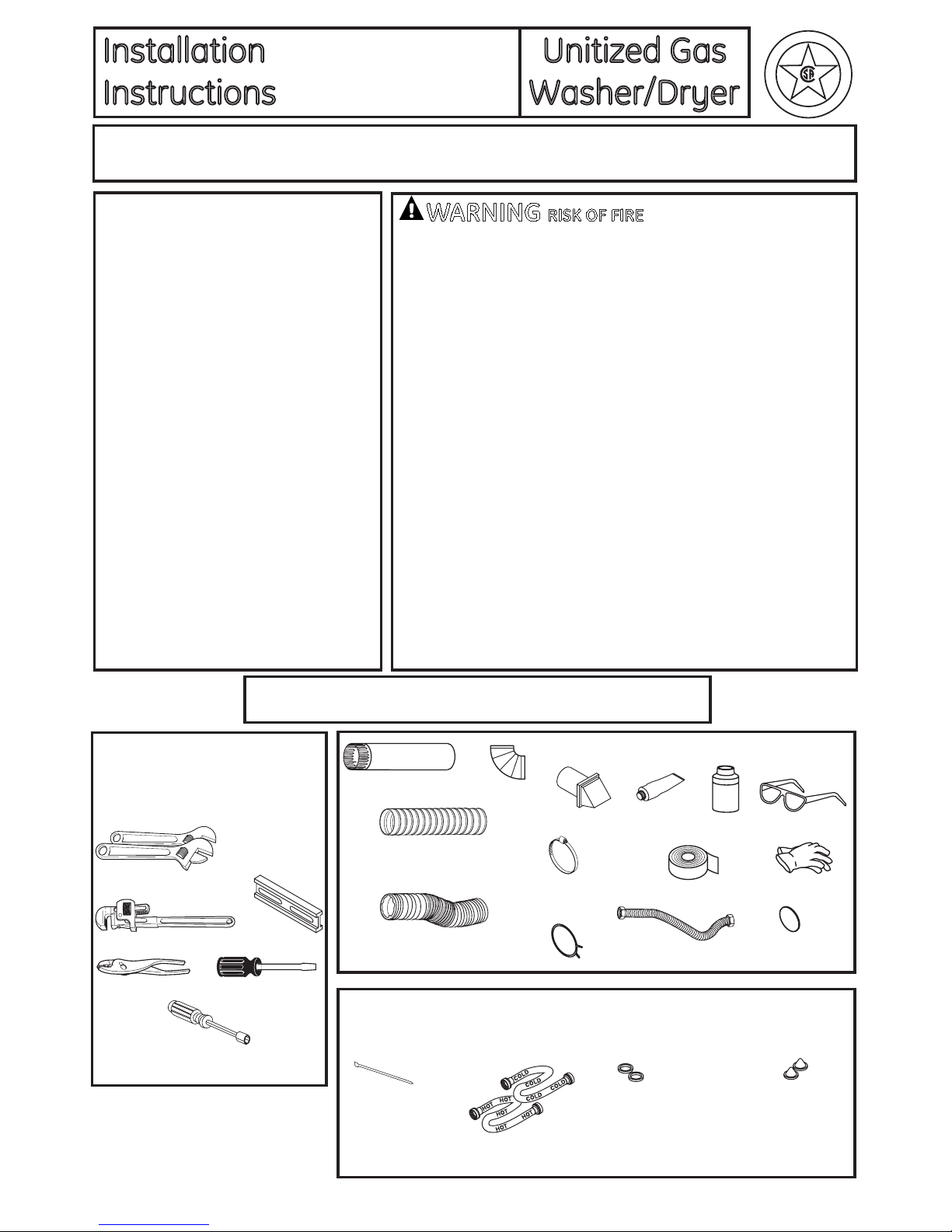
Installation Instructions
8
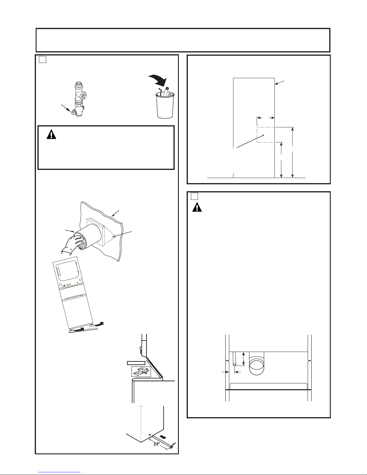
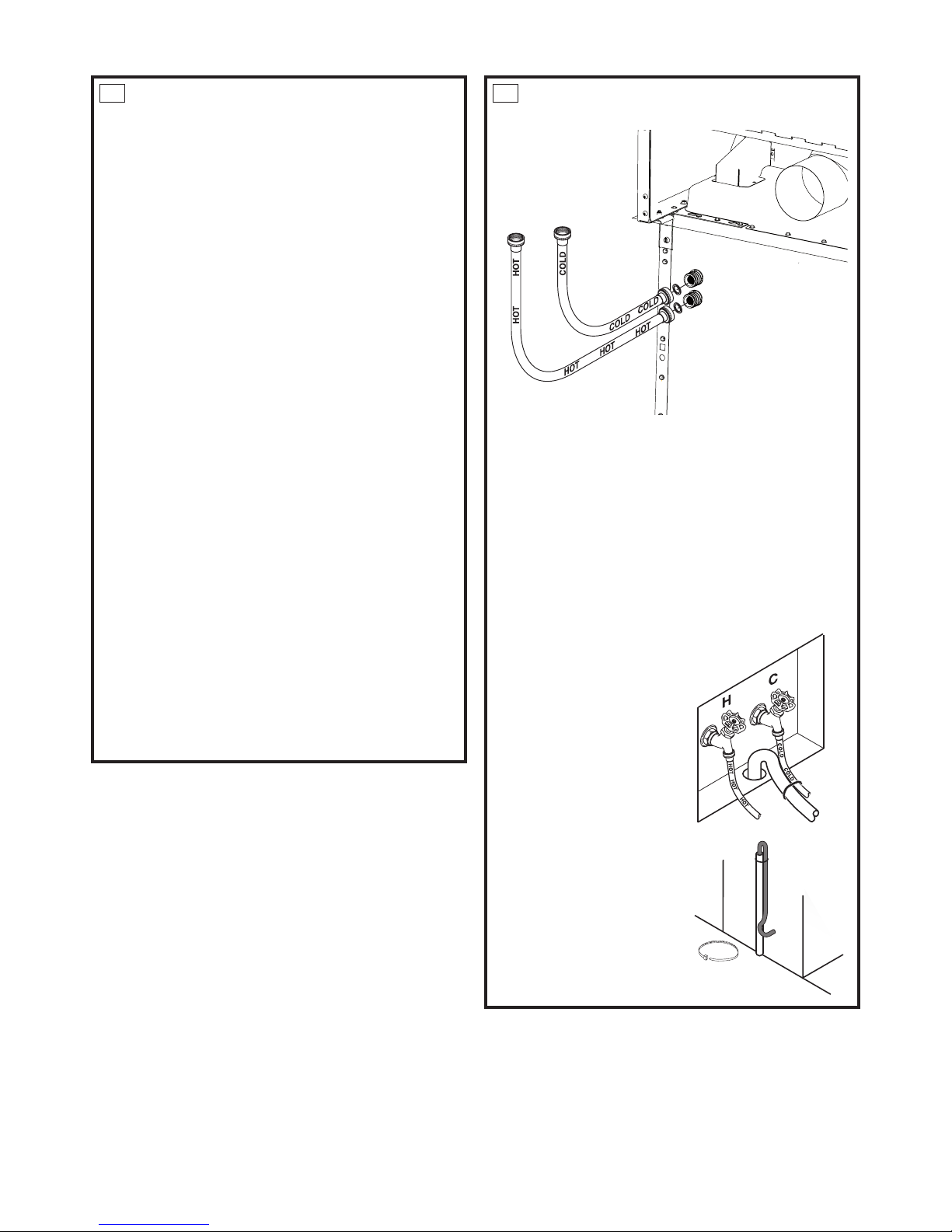
STANDARD REAR EXHAUST
(Vented above oor level)
8
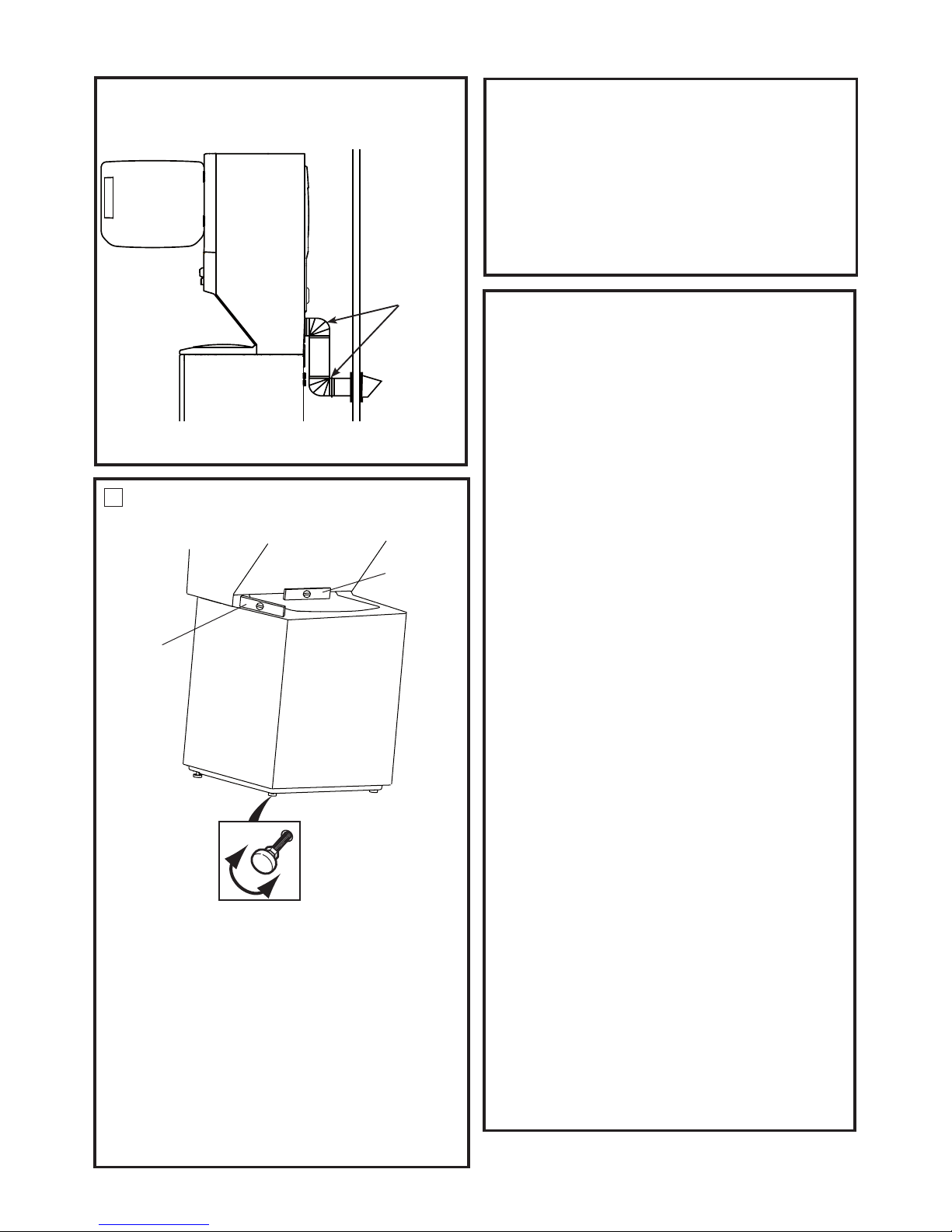
LEVELING AND STABILIZING YOUR
APPLIANCE
Level and stabilizing your appliance
1. Carefully move the appliance to its nal location.
Gently rock the appliance into position. It is important
not to damage the rubber leveling legs when moving
your appliance to its nal location. Damage legs can
increase appliance vibration. It may be helpful to spray
window cleaner on the oor to help move your appli-
ance to its nal position.
Note: do not use washer cover to lift the unit.
2. To ensure the appliance is level and solid on all four
legs, tilt the appliance forward so the rear legs are off
the ground. Gently set the appliance back down to al-
low the rear legs to self adjust.
LEVEL
SIDE-TO-SIDE.
2 LEVELING LEGS
LEVEL
FRONT-TO-BACK.
CONNECTING THE DRYER
TO HOUSE VENT
RIGID METAL TRANSITION DUCT
• For best drying performance, a rigid metal transition duct is
recommended.
• Rigid metal transitions ducts reduce the risk of crushing and
kinking.
UL-LISTED FLEXIBLE METAL (SEMI-RIGID) TRANSITION DUCT
• If rigid metal duct cannot be used, then UL-listed exible metal
(semi-rigid) ducting can be used (Kit WX08X10077).
• Never install exible metal duct in walls, ceilings, oors or
other enclosed spaces.
• Total length of exible metal duct should not exceed 8 feet
(2.4m).
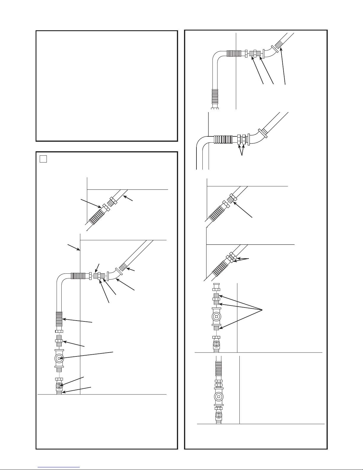
• For many applications, installing elbows at both the dryer and
the wall is highly recommended (see illustrations on page 9).
Elbows allow the dryer to sit close to the wall without kinking
and or crushing the transition duct, maximizing drying
performance.
• Avoid resting the duct on sharp objects.
UL-LISTED FLEXIBLE METAL (FOIL-TYPE) TRANSITION DUCT
• In special installations, it may be necessary to connect the
dryer to the house vent using a exible metal (foiltype) duct.
A UL-listed exible metal (foil-type)duct may be used ONLY
in installations where rigid metal or exible metal (semi-rigid)
ducting cannot be used AND where a 4” diameter can be
maintained throughout the entire length of the transition
duct.
• In Canada and the United States, only the exible metal(foil-
type) ducts that comply with the “Outline for Clothes Dryer
Transition Duct Subject 2158A” shall be used.
• Never install exible metal duct in walls, ceilings, oors or
other enclosed spaces.
• Total length of exible metal duct should not exceed 8 feet
(2.4m).
• Avoid resting the duct on sharp objects.
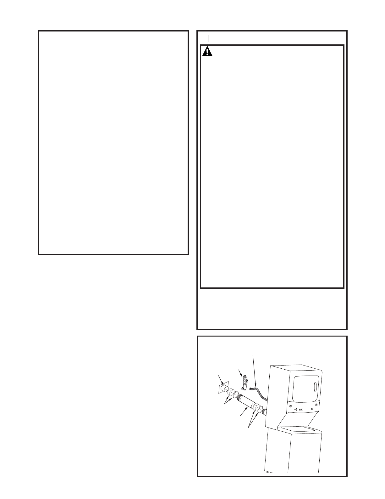
• For best drying performance:
1. Slide one end of the duct over the clothes dryer
outlet pipe.
2. Secure the duct with a clamp.
3. With the dryer in its permanent position, extend the
duct to its full length. Allow 2” of duct to overlap the
exhaust pipe. Cut off and remove excess duct. Keep
the duct as straight as possible for maximum airow.
4. Secure the duct to the exhaust pipe with the other
clamp.
ELBOW HIGHLY
RECOMMENDED
RECOMMENDED
CONFIGURATION
TO MINIMIZE
EXHAUST BLOCKAGE
NOTE: ELBOWS WILL PREVENT DUCT KINKING AND COLLAPSING
3. With the appliance in its nal position, place a level on
top of back part of the washer lid and check it side to
side, then check front to back. Screw the front leveling
legs up or down to ensure the appliance is resting solid
on all four legs (no rocking or the appliance should ex-
ist), turn the lock nuts on each leg up toward the base
of the unit and snug with a wrench.
Note: Keep the leg extension at minimum to prevent
excessive vibration. The farther out legs are extended, the
more the unit will vibrate.