GE WSLP1500H0WW How to use

GE Appliances
General Electric Company
Louisville, Kentucky 40225 31-9240
GE Compact Washer
Technical Service Guide
March 2015
GE Appliances
WSLP1500H0WW
WSLS1500H0WW
WSLP1500H1WW
WSLS1500H1WW
WSLP1500H2WW
WSLS1500H2WW

– 2 –
IMPORTANT SAFETY NOTICE
The information in this service guide is intended for use by
individuals possessing adequate backgrounds of electrical,
electronic, and mechanical experience. Any attempt to repair a
major appliance may result in personal injury and property
damage. The manufacturer or seller cannot be responsible for the
interpretation of this information, nor can it assume any liability in
connection with its use.
WARNING
To avoid personal injury, disconnect power before servicing
this product. If electrical power is required for diagnosis or test
purposes, disconnect the power immediately after performing the
necessary checks.
RECONNECT ALL GROUNDING DEVICES
If grounding wires, screws, straps, clips, nuts, or washers used to
complete a path to ground are removed for service, they must be
returned to their original position and properly fastened.
GE Appliances
Technical Service Guide
Copyright © 2015
All rights reserved. This service guide may not be reproduced in whole or in part
in any form without written permission from the General Electric Company.

– 3 –
Table of Contents
(Continued next page)
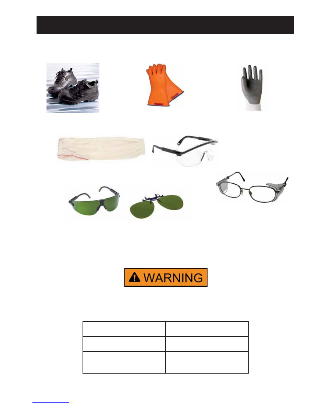
Safety Requirements.....................................................................................................................................................................5
Introduction.......................................................................................................................................................................................6
Nomenclature...................................................................................................................................................................................7
3URGXFW6SHFL¿FDWLRQV ..................................................................................................................................................................8
(OHFWULFDO6SHFL¿FDWLRQV .......................................................................................................................................................8
Tools Needed.............................................................................................................................................................................8
Installation Instructions................................................................................................................................................................9
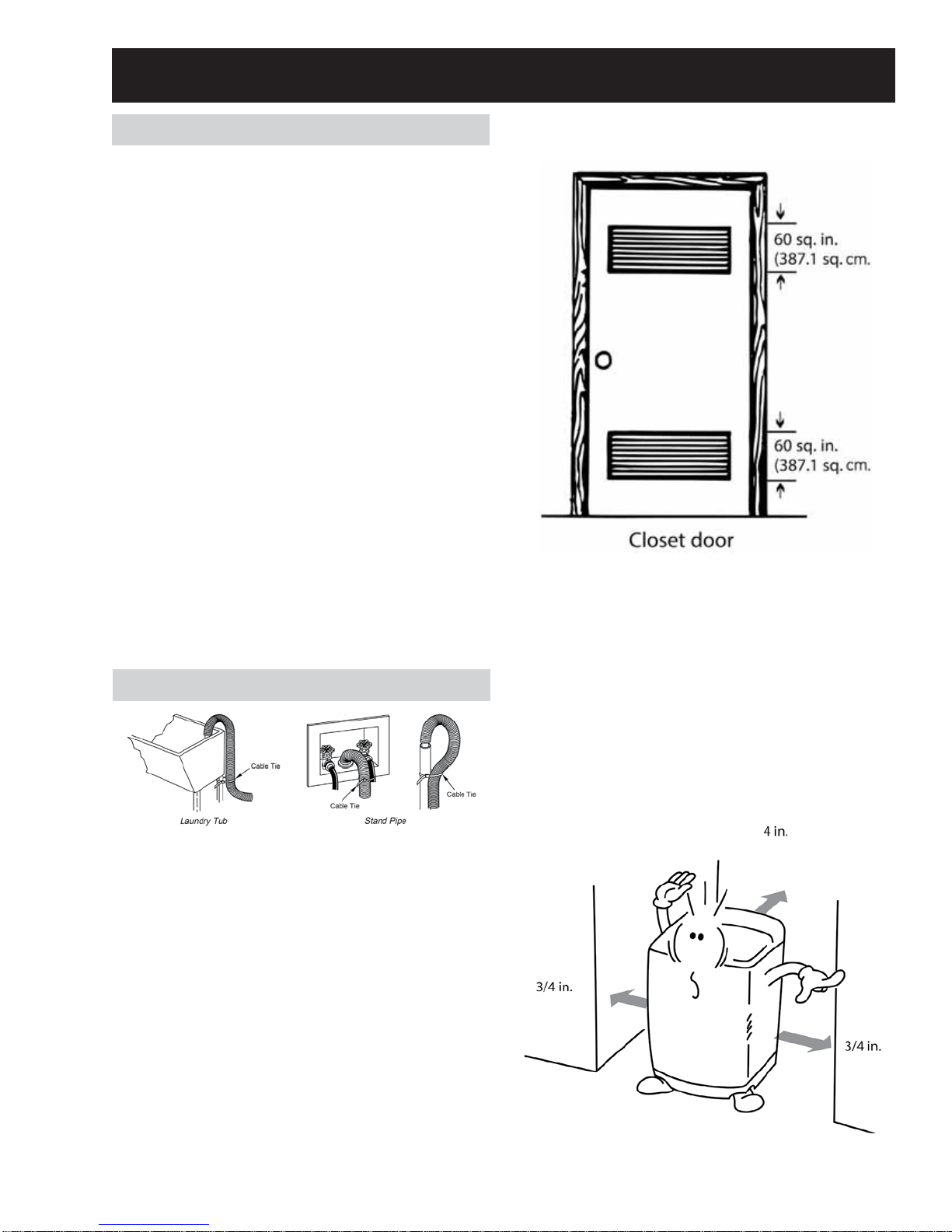
Location.......................................................................................................................................................................................9
Plumbing.....................................................................................................................................................................................9
Leveling the Washer..............................................................................................................................................................10
Electrical Wiring.......................................................................................................................................................................10
Operation............................................................................................................................................................................................11
Redistribution Attempt.........................................................................................................................................................12
Drain and Spin Operation....................................................................................................................................................12
Program Time Chart.......................................................................................................................................................................13
Dispensers..........................................................................................................................................................................................14
Detergent Dispenser..............................................................................................................................................................14
Bleach Dispenser.....................................................................................................................................................................14
Fabric Softener Dispenser...................................................................................................................................................14
Special Features...............................................................................................................................................................................15
Easy to Clean Lint Filter........................................................................................................................................................15
Non-Powered Water Recirculation.................................................................................................................................15
Component Locator Views..........................................................................................................................................................16
Control Board and Wire Connection Locator.............................................................................................................18
UI Board.......................................................................................................................................................................................18
Diagnostics.........................................................................................................................................................................................19
Service Mode.............................................................................................................................................................................19
Fault Codes.........................................................................................................................................................................................20
Cabinet and Structure...................................................................................................................................................................21
Front Control Panel.................................................................................................................................................................21
Control Panel Removal.........................................................................................................................................................21

– 4 –
UI and Machine Control Removal....................................................................................................................................22
Rear Component Cover Removal....................................................................................................................................22
Fill System...........................................................................................................................................................................................23
Water Valve...............................................................................................................................................................................23
Water Valve Dispenser Box Removal............................................................................................................................23
Diagnosing the Water Valve..............................................................................................................................................24
Pressure Sensor.......................................................................................................................................................................25
Pressure Sensor Removal....................................................................................................................................................25
Pressure Sensor Error Codes.............................................................................................................................................26
Water Levels: Hz to Inches..................................................................................................................................................27
Top Cover....................................................................................................................................................................................28
Lid Switch....................................................................................................................................................................................29
Cabinet and Structure...................................................................................................................................................................30
Pulsator........................................................................................................................................................................................30
Wash Basket.............................................................................................................................................................................31
Drain Pump/Cleanout...........................................................................................................................................................32
Belt Protector............................................................................................................................................................................33
Drive Pulleys .............................................................................................................................................................................33
Drive Motor and Belt..............................................................................................................................................................34
Shaft Assembly/Brake Overview......................................................................................................................................35
Drain/Mode Shifter Operation...........................................................................................................................................35
Brake Adjustment...................................................................................................................................................................36
Shaft Assembly.........................................................................................................................................................................37
Capacitor.....................................................................................................................................................................................37
Outer Tub/Suspension Assembly.....................................................................................................................................38
Wire Harness.............................................................................................................................................................................39
Cabinet Handle........................................................................................................................................................................41
Base Assembly.........................................................................................................................................................................41
Wiring Diagram................................................................................................................................................................................43
Warranty.............................................................................................................................................................................................44

– 5 –
Prior to disassembly of the washer to access components, GE Factory
Service technicians are REQUIRED to follow the Lockout / Tagout
(LOTO) 6 Step Process:
Safety Requirements
GE Factory Service Employees are required to use safety glasses with side shields, safety gloves and
steel toe shoes for all repairs.
Steel Toed Work Boot Electrically Rated Glove and
Dyneema® Cut Resistant
Glove Keeper Dyneema®Cut Resistant
Glove
Plano Type Safety Glasses
Prescription Safety Glasses
Safety Glasses must be ANSI
Z87.1-2003 compliant
Brazing Glasses
Cut Resistant Sleeve(s)
Step 1
Plan and Prepare Step 4
Apply LOTO device and lock
Step 2
Shut down the appliance Step 5
Control (discharge) stored energy
Step 3
Isolate the appliance Step 6
“Try It” verify that the appliance is
locked out

– 6 –
The new GE Compact Washer has the following features:
• (OHFWURQLF2QH7RXFK&RQWUROVZLWK/('UHDGRXWVLPSOL¿HVF\FOHVHOHFWLRQDQGSURYLGHVDFFXUDWHF\FOH
times.
• One Touch Load Sensing in Normal wash eliminates guesswork and reduces water waste.
• Eight wash cycles provide a setting for every load, from heavy cottons to casual synthetics. Includes
settings for light to heavy soil, regular, whites, and colors, casual and delicate fabrics.
• Three wash/rinse temperatures.
• Water levels can be adjusted manually to reduce water use per cycle.
• My Cycle saves a favorite cycle for future use.
• Dispensers adds diluted detergent and fabric softener at the correct time during the wash or rinse cycles.
• Built-in status indicators display fault codes.
• The wash tub is constructed of durable stainless steel.
• UV stabilizers are utilized on the control panel, top cover, and lid to prevent yellowing when exposed to
sunlight.
Introduction

– 7 –
Nomenclature
The nomenclature breaks down and explains what the letters and numbers mean in the model number. The
¿UVWWZRFKDUDFWHUVRIWKHVHULDOQXPEHULGHQWLI\WKHPRQWKDQG\HDURIPDQXIDFWXUH7KHOHWWHUGHVLJQDWLQJ
the year repeats every 12 years.
Example: LA123456S = June, 2013
A – JAN
D – FEB
F – MAR
G – APR
H – MAY
L – JUN
M – JUL
R – AUG
S – SEP
T – OCT
V – NOV
Z – DEC
2024 – Z
2023 – V
2022 – T
2021 – S
2020 – R
2019 – M
2018 – L
2017 – H
2016 – G
2015 – F
2014 – D
2013 – A
Mini Manual Location Model Serial ID Tag
Brand
W - GE Washer
W S L P 1 5 0 0 H 0 W W
Capacity/Configuration
L - Large
Feature Package
S - Unitized Compact
Control Platform
S - Stationary
P - Portable
Speed
Engineering Digit
Engineering Revision
US Voltage
Series
Color
WW - White
The Model Serial ID Tag is located on
the back cabinet of washer.
The Mini Manual is in a storage bag
on the inside left rear of the rear
component cover.

– 8 –
3URGXFW6SHFL¿FDWLRQV
(OHFWULFDO6SHFL¿FDWLRQV
AC VOLTAGE
• Drive Motor: 120 VAC
Approximately 4 - 5 ohms red to blue and
yellow to blue
• Drain/Mode Shift Motor: 120 VAC
Approximately 2,300 ohms white to blue and
Approximately 1,300 brown to blue
• Drain Pump: 120 VAC Approximately 27.6 ohms
• Water Valve Coils: 120 VAC
Approximately 1178 ohms
DC VOLTAGE
• Pressure sensor: 5 VDC
Approximately 22 ohms
FORELECTORSTATICS:Besuretomakeanearthgroundconnectionbeforereplacinganyelectroniccomponents
topreventelectrostaticdamagetothem.Thisisdonebytouchingagoodearth groundontheappliancebeing
repaired.
Tools Needed
• Adjustable Pliers
• Pliers
• #3 Phillips screwdriver
• #2 Phillips screwdriver
• 1 7/16th socket
• 14 mm socket
• 13 mm socket
• 10 mm socket
• 8 mm socket

– 9 –
Location
• :DVKHUPXVWEHLQVWDOOHGRQ¿UPÀRRULQJ
&RQFUHWHÀRRULQJLVEHVWEXWZRRGEDVHLV
VXȻFLHQWSURYLGLQJÀRRUVXSSRUWPHHWV)+$
standards.
• Washer should not be installed on rugs or
exposed to the weather.
• Install or store washer where it will not be
exposed to temperatures below freezing.
• Minimum clearances between washer and
adjacent walls or other surfaces are: 2 inches
either side, 2 inches front, and 3 inches rear.
• 0LQLPXPYHUWLFDOVSDFHIURPÀRRUWRRYHUKHDG
shelves, cabinets, ceilings, etc., is 96 inches.
• Closet doors must be louvered or otherwise
ventilated and have at least 60 square inches
open area for washer only, or if the closet
contains both a washer and dryer, doors must
contain at least 120 square inches of open area,
equally distributed.
Plumbing
• Water pressure must be 10 psi minimum to 150
psi maximum dynamic pressure measured at
faucet.
• Water temperature on household water heater
should be set to deliver water at 120°F to 150°F
(50°C to 66°C) in the washer when HOT wash is
selected.
• 6KXWRȺYDOYHVVKRXOGEHVXSSOLHGIRUERWKKRW
and cold water lines.
• Drain water into a standpipe or laundry tub.
The discharge height must not be less than 30
inches nor more than 8 feet above the base of
the washer. The standpipe must be 1-1/2 inches
minimum inside diameter and must be open to
the atmosphere.
Installation Instructions
Distance Between Drain Hose and the Wall
Distance between drain hose and the wall should be
at least 4 inches, and the distance from the sides to
the wall should be at least 3/4 inches.
NOTE: The clearances stated are minimums.
Consideration must be given to providing adequate
clearances for installation and servicing.

– 10 –
Electrical Wiring
National Electrical Codes or prevailing local codes
and ordinances must be followed.
Electrical Rating
Voltage AC..........................................................120
Hertz......................................................................60
Total connected load amperage............10.0
For use on adequately wired 120 volt, 15 amp circuit
having 2 wire service with a separate ground wire.
This appliance must be grounded for safe operation.
If the spin basket is not in the center or “unleveled,”
level the washer by turning the adjustable legs to
set the washer horizontal.
• Limited to only the stationary model
• Portable model is not applicable
Leveling the Washer
Excessive vibration will occur if the washer is not
leveled. This will also trip the unbalance switch and
stop the washer. Check to ensure the washer is
level. With the lid open, the spin basket should be
centered in the opening as shown in the “leveled”
view.

– 11 –
Operation
1. Water Temp: Used to select Water Temperature. Pressing the button allows user to select Hot, Cold and
Warm (Hot + Cold) respectively.
2. Options: Pressing Options allows the consumer to make changes to cycles depending on material needs.
Gentle spin for delicate materials, extra rinse for heavier materials, and swimwear.
3. Load Size: Load Size adjusts water levels. Load Size for a Normal cycle is automatically selected through
load sensing. The available settings are: Small, Small-Medium, Medium, Medium-Large, Large, Large-Ex
Large, Ex Large.
• The “H1” models will be load sensing for all cycles and will not have the capability of selecting load
sizes as listed above. It will only have a DEEP FILLRSWLRQ,IVHOHFWHGWXEZLOO¿OOWR(;/$5*(ZDWHU
level for all cycles.
4. Delay Wash: The delay wash time increases 1 hour per button press.
5. Process: Use to select Soak, Wash, Rinse and Spin functions as desired. Pressing the Process button with
the Load Size button will mute the end of cycle signal.
6. Cycles8VHIRUVHOHFWLQJZDVKSURJUDP7KLVEXWWRQDOORZVXVHUWRVHOHFWGLȺHUHQWSURJUDPVIRU
GLȺHUHQWNLQGVRIODXQGU\DQGVRLOOHYHO3UHVVLQJDQGKROGLQJWKH3URFHVVDQG&\FOHVEXWWRQVIRU
seconds will lock the control.
7. Start/Pause: Used to start or pause the wash cycle (Example: If another article of clothing needs to be
added after the wash has already started).
8. Power8VHWRWXUQWKHSRZHURQRURȺ7KHSRZHUZLOOWXUQRȺDXWRPDWLFDOO\LQDERXWVHFRQGVDIWHUD
completed cycle.
Operating Controls

– 12 –
Drain and Spin Operation
When attempting to drain the water from the tub
during any selected cycle, it is normal for the drain
SXPSWRF\FOHRQDQGRȺWKUHHWLPHVZLWKLQWKH¿UVW
30 seconds. It will remain on the third time.
Once the water is drained from the basket, the
SXPSZLOODJDLQWXUQRȺ7KHZDVKHUZLOOVLWLGOH
approximately 2 minutes letting the water drain
from the clothes. After two minutes of idle time, it
will turn back on.
The drive motor will turn on, spinning the basket and
ramping up to the target spin speed. It does this by
WXUQLQJWKHGULYHPRWRURQDQGRȺDSSUR[LPDWHO\
times, increasing speed each time. The drive motor
will then remain on until the spin part of the cycle
has completed.
This operation allows water that had been spun
out of the clothes during the spin to drain without
causing a suds lock.
Redistribution Attempt
The washer will attempt to redistribute an out of
EDODQFHORDGRQFHSHUF\FOHLQWKH¿QDOVSLQXS
The redistribution attempt consists of the following
sequence.
• The washer will try to reach the target spin
speed one time.
• If the washer cannot get to the target spin
speed, it will stop, reset the cycle time to 21
PLQXWHVWKHQ¿OOZLWKZDWHUDSSURSULDWHIRUWKH
selected cycle load.
• 2QFH¿OOLQJLVFRPSOHWHWKHZDVKHUZLOOVZLWFK
to agitate in order to jog the clothes and
redistribute them in the basket.
• After the redistribution attempt is complete,
the water will be drained and the washer will
attempt to reach the target spin speed again.
If the target spin speed is not reached, the cycle will
be aborted and “Unbalanced Error” will be shown in
the display.
NOTE7RFOHDUWKLVHUURUSRZHURȺWKHFRQWURO
Manually redistribute the load in the basket. Power
the control back on, select spin and load size, press
start. If the target spin speed is reached, the cycle
will continue until it is completed.

– 13 –
Program Time Chart
WASH OPTION
Swimwear Use this program to reduce moisture in the machine and on the laundry.
Extra Rinse A second deep rinse will be added. (Except for speed wash.)
Gentle Spin High speed spin is not operated.

– 14 –
Dispensers
Detergent Dispenser
Open the Detergent Dispenser and deposit the
appropriate amount of detergent. Some detergents
MUST be fully dissolved before adding to the
machine to get the best wash results. Check the
instructions on the detergent package.
Bleach Dispenser
Before starting the washer, pour measured amount
of bleach directly into bleach dispenser. Avoid
VSODVKLQJRURYHU¿OOLQJ3RZGHUHGEOHDFKPXVWEH
mixed with water before pouring.
Fabric Softener Dispenser
The fabric softener dispenser is built into the top
of the basket. Dilute fabric softener with water.
Undiluted fabric softener may result in spots that
look like oil stains. Fabric softener automatically
dispenses for the rinse cycle. If extra rinse is
selected, the softener must be added manually.

– 15 –
Special Features
Easy to Clean Lint Filter
Non-Powered Water Recirculation

– 16 –
Component Locator Views
Under Rear Component Cover

– 17 –
Rear
Bottom
Component Locator Views continued

– 18 –
For front view, see the Operating Controls section for button operation description.
*On "H1" models the 6 LED's for load sizes are removed.
Component Locator Views continued
Control Board and Wire Connection Locator
UI Board
"H1 Model"

– 19 –
Diagnostics
Service Mode
To enter into Service mode on engineering models
“H0”, press and hold Load Size, Process and Power
pad.
On engineering models “H1~H2”, press and hold
Deep Fill, Process and Power.
All LEDs will turn on in initial state of entering
Service mode. Pressing the Start button will
DGYDQFHWKURXJKGLȺHUHQWService modes.
To exit Service mode, press Power, then unplug the
washer, or go through all the tests below.
NOTE: It is important to note that fault codes should
only be used to help identify components which
require testing.
Never replace a part based solely on an fault code.
The control can generate a false fault code if the
right conditions exist. Use the code only as a
reference and always check the component before
replacing.
Test Item Checked Displayed
Initial state upon entering Service
mode All LED's on. Water level frequency
checked with no water in the tub. "88" will be displayed quickly.
Then the version number (07 for
HO, 10 for H1, 11 for H2.
Then 63 ~ 68 for the water level.
Press Start 1 time Laundry amount detection Numerous numbers will show
in the display which are the
electromotive force values. Value
range from 130 to 160 with no
load.
Press Start 2 times Cold water valve EP
Press Start 3 times Hot water valve 00
Press Start 4 times Nothing tested 54
Press Start 5 times Drain/Mode shift motor engage
for agitate 55
Press Start 6 times Drain/Mode shift motor disengage
for spin 56
Press Start 7 times Drain pump on 57
Press Start 8 times $XWRRȺ $OO/('VRȺ

– 20 –
Fault Codes
Fault
Code Name Description Repair Action
Water level does
not rise to the
set level in 60
minutes
For “H1~H2”
models Set time
is 12 minutes.
• House water supply
closed
• Clogged valve and/or
hose screens
• Clogged, kinked or
pierced pressure hose or
chamber hose connect
• Open house water supply
• Clean valve and/or hose screens
• Clean or replace hose, clean chamber
where hose connects
Water does
not drain out of
tub within 60
minutes
• Drain pump clogged
• Drain pump inoperative
• Pinched internal/
external drain hose
• Clogged in tub
• Pressure sensor
defective
• Clear clog from pump
• Replace drain pump
• Repair/replace hoses
• Clear clog from tub
• Replace pressure sensor
Unbalanced load • Washer not level
• Uneven clothes
distribution
• Balance ring empty or
basket out of round
• Pressure sensor bad
• Level washer per installation instructions
• &XVWRPHU(GXFDWLRQ6HSDUDWHGLȺHUHQW
materials
• Manually redistribute materials
• &KHFNEDODQFHULQJIRUÀXLGLIQRQH
replace
• Replace pressure sensor
Water level too
high • Leaking water valve
• Pressure sensor
frequency out of range
• Hole in pressure sensor
hose or disconnected
• Harness connecter not
connected or damaged
• Replace water valve
• Replace pressure sensor
• Replace pressure hose
• Reconnect connecter or replace harness
Lid shows Open
when closed,
intermittent
during spin
• Lid warped or damaged
• No lid magnet
• Lid switch defective
• Replace damaged part
• Replace/reinstall missing magnet
• Replace Machine Control
Pressure sensor • Not connected
• Out of range/ Damaged
• Reconnect harness connecter
• Replace sensor
Load size sensor • Will not sense load size • Check motor and clutch operation
• Check belt tension, tighten if necessary
• Check harness and connecters from
control to the motor
• If above is good, replace control
This manual suits for next models
5
Table of contents
Other GE Washer manuals

GE
GE GE Profile WCCB1030J Manual

GE
GE Profile WPDH8850 Original instructions

GE
GE GTW750CPLDG How to use

GE
GE GTWP1000MWW Assembly instructions

GE
GE GTWP2005M Manual

GE
GE WWA8800R User manual

GE
GE GTW540 Original instructions

GE
GE WWA8330G Installation instructions

GE
GE WPSQ4160 User manual

GE
GE Washers User manual

GE
GE GE Profile WNRD2050DWC User manual

GE
GE GBVH5140 Original instructions

GE
GE Spacemaker WWP1170G User manual

GE
GE WISR106 User manual

GE
GE GTWN4250DWS Manual

GE
GE WCCB1030D1WC Warranty User manual

GE
GE WWM657M User manual

GE
GE WCCB1030HWC How to use

GE
GE WWA8326L User manual

GE
GE WLW1500R Installation instructions