manuals.online logo
Brands
  1. Home
  2. •
  3. Brands
  4. •
  5. GE
  6. •
  7. Water Pump
  8. •
  9. GE Monogram ZPK1 User manual

GE Monogram ZPK1 User manual

Installation
Instructions
ZPK1
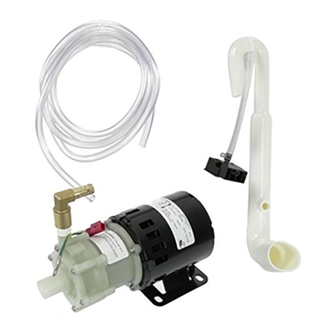
Icemaker Drain Pump
WARNING
Electrical Shock Hazard
Disconnect power before servicing.
Replace all panels before operating.
Failure to do so can result in death
or electrical shock.
IMPORTANT: Connect drain pump to house drain
in accordance with all state and local codes and
ordinances.
Note:
• This drain pump is designed to pump water to a
maximum height of 10 feet.
• To minimize condensation on the drain tube,
insulate the full length of the tube from the pump to
the drain.
Kit Contents:
•Drain Pump
• Drain Tube, 5/8" ID x 4-1/2" (bin to pump reservoir inlet)
• Drain Tube, 3/8" ID x 10 ft. (pump to house drain)
• Vent Tube, 3/8" ID x 32" (pump to cabinet back)
• 3 Cable Clamps (Secures vent tube to back of product)
• 5 Screws, #8 x 1/2" (secures vent hose clamps to back of cabinet
and pump to base plate)
• 2 Hose Clamps, 1/2" (secures vent and drain tube to pump)
• Hose Clamp, 5/8" (secures drain tube to bin)
If Icemaker Is Presently Installed:
• Push the selector switch to OFF.
• Unplug icemaker or disconnect power.
• Shut off water supply. Wait 5 to 10 minutes for the ice
to fall into the storage bin. Remove all ice from the
bin.
• Disconnect the water inlet line from the water valve.
• If the icemaker is installed between cabinets, pull
icemaker out of the opening.
• Unscrew the drain cap from the bottom of the water
pan located inside the storage bin. Allow water to
drain completely. Replace the drain cap.
Disconnect Water Inlet
For connection in Front at Water Valve:
• Remove the 2 screws in the front lower access panel
and the 2 screws from the base grille area. Pull panel
forward to remove.
For Connection at Rear of Icemaker:
•␣ Pull icemaker forward.
• For compression nut, diconnect water line as shown.
• For union between copper tubing, disconnect union.
1/4" Copper Tubing Tubing
Clamp
Ferrule
(Sleeve)
1/4"
Compression Nut
Icemaker Connection
PROCEED TO STEP 1
Water
Inlet
Water
Outlet
-2-
STEP 1 Remove Original Parts
• Remove the 2 screws in the front lower access panel
and the 2 screws from the base grille area. Pull to
remove. Set aside screws and panel.
• Unplug power cord from rear cover.
• Remove screws holding the rear cover. Retain screws.
Carefully pull rear cover away from drain tube.
• Remove old drain tube and clamp attached to bin.
Discard the tube, retain the clamp for re-installation.
• Install the new drain tube with the new 5/8" clamp.
Remove Screws
Remove Screws
5/8" Hose Clamp
Drain Tube
(Bin to Pump)
STEP 2 Connect Electrical
A. Position pump at the right side, just outside of the
opening.
B. Remove clamp and screw attached to the icemaker
power cord. Attach the drain pump power cord to
the icemaker base with original clamp and screw.
C. Plug the icemaker power cord into the side of the
pump.
STEP 3 Install New Tubing
A. Attach new drain tube to pump check valve outlet
with new 1/2" hose clamp.
B. Attach vent tube to pump with new 1/2" hose
clamp.
C. Coil icemaker power cord into a 4" dia. coil and
secure with electrical tape. Place the coil over the
top of the pump.
D. Carefully slide the drain pump into the bottom
right side. The front tab on the pump should slip
into the rectangular slot on the icemaker floor. It
may be necessary to tip the pump slightly to engage
the tab.
Note: The pump must be in position before connect-
ing the bin drain tube. See Step 4.
Ground
Wire
Remove Clamp
and Screw
to Release
Icemaker
Power Cord
Pump
Power
Cord
Plug Icemaker
Power Cord
Into Pump
B
C
Position Pump
Just Outside
of Opening
A
Bin
Drain
Inlet Vent Tube
Connection
Slide Pump Tab
Into Slot
D
C
Coil Icemaker
Power Cord
B
Drain Tube (Pump
to Household Drain)
A
-3-
STEP 4 Install Bin Drain Tube
A. Attach drain tube from bin to pump with
original hose clamp from old drain tube.
B. Secure the pump to the base with the 2
supplied screws.
STEP 5 Secure Vent Tube
• Place rear cover against the back of the icemaker.
Route the vent tube and drain tube through cutouts
in the rear cover.
• Secure rear cover with original screws.
• Secure vent tube to the back of the icemaker with the
3 clamps and 3 remaining screws.
• Route drain tube to house drain.
Vent Tube
Mounting Clamp
and Screw
Vent Tube
Original Icemaker
Power Cord
Pump Mounting Screws
Connect
Bin Drain
Tube
A
B
STEP 7 Finalize Installation
• Connect power.
• Push selector switch to ON.
• Wait for rinsing cycle, approximately 5 minutes, to be
sure the icemaker is operating properly.
Pub. No. 49-60155 SPECIFICATIONS SUBJECT TO CHANGE WITHOUT NOTICE DWG. NO. 197D4493P001
(N.D. 305) 11/01
STEP 6 Connect Water Supply
• Feed water supply tubing through one of the two
access holes in the rear cover.
• Slide the icemaker into its permanent location.
IMPORTANT: Check to be sure water and drain lines
do not kink or bind. This could interfere with
icemaker operation.
• Bend the tubing to meet the connection at the water
valve inlet at the front.
• Remove the water valve inlet cover and attach copper
tubing with a compression nut and sleeve.
• Check to be sure copper tubing does not touch the
side wall or other parts inside the cabinet.
• Turn on the water and check all connections for
leaks.
Water
Line
Access
Holes
Water
Inlet
Water
Outlet
• Check to be sure copper tubing does not touch the
side wall or other parts inside the cabinet.
• Turn on the water and check all connections for
leaks.
For connection in Front at Water Valve:
• For threaded connection, use ferrule and compres-
sion nut to secure the line as shown on page 1.
• For water tube exiting rear access cover, connect
water line using 1/4" union or coupling.
For Water Connection at Rear:
Water
Supply
Line
Drain Hose
From Drain
Pump
Vent Hose
From Drain Pump
Coupling
(Not Supplied)
Nut
(Supplied)
Ferrule
(Not Supplied)
Line to
Icemaker
Nut
(Supplied)

Other GE Water Pump manuals

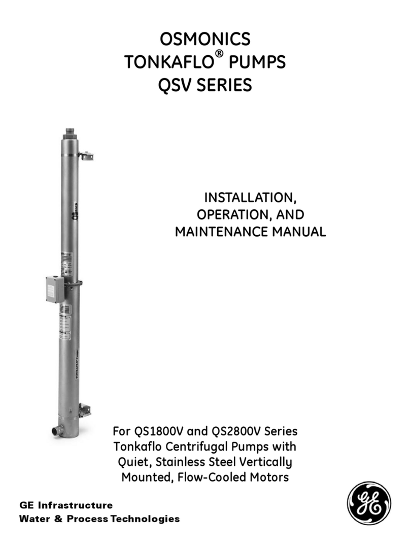
GE OSMONICS TONKAFLO QS1800V Series User manual

GE

GE OSMONICS TONKAFLO QS1800V Series User manual

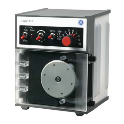
GE Peristaltic Pump P-1 User manual

GE

GE Peristaltic Pump P-1 User manual

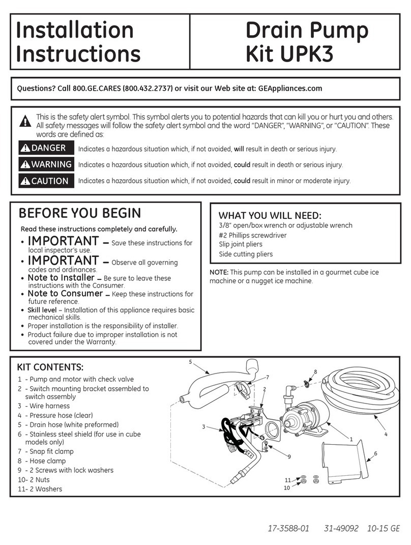
GE UPK3 User manual

GE

GE UPK3 User manual

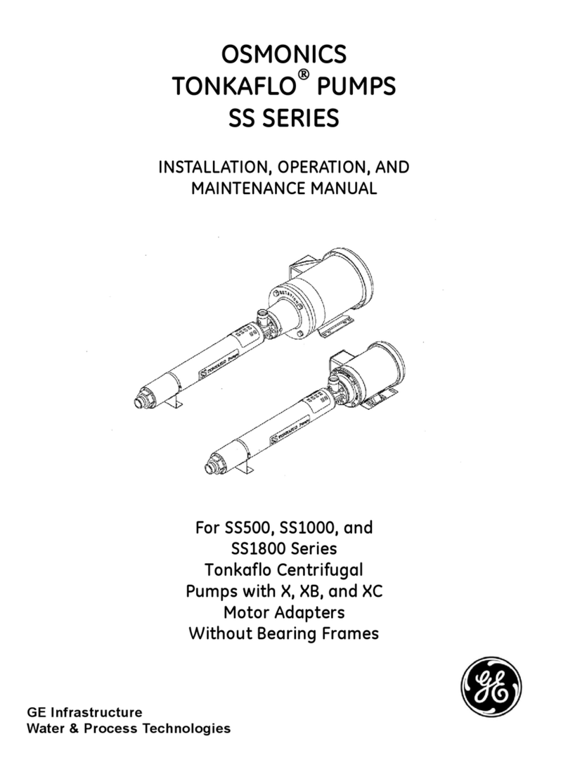
GE OSMONICS TONKAFLO SS Series User manual

GE

GE OSMONICS TONKAFLO SS Series User manual

GE 5514 User manual

GE

GE 5514 User manual

GE UPK3 User manual

GE

GE UPK3 User manual

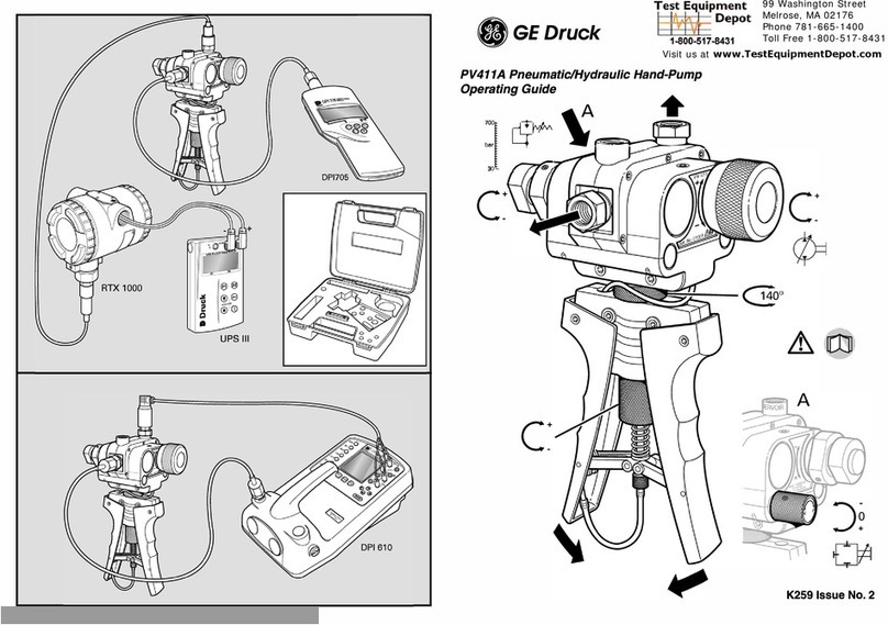
GE PV411A User manual

GE

GE PV411A User manual

GE OSMONICS TONKAFLO SS1000 SERIES User manual

GE

GE OSMONICS TONKAFLO SS1000 SERIES User manual

GE UPK4 User manual

GE

GE UPK4 User manual

GE PV411A User manual

GE

GE PV411A User manual

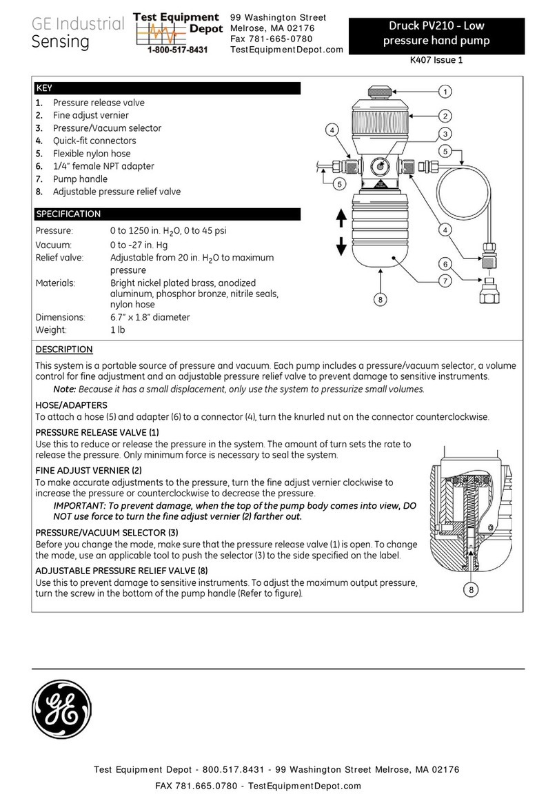
GE Druck PV210 User manual

GE

GE Druck PV210 User manual

Popular Water Pump manuals by other brands

Everflo EFHP-2000 owner's manual

Everflo

Everflo EFHP-2000 owner's manual

Wacker Neuson PST2 400 Operator's manual

Wacker Neuson

Wacker Neuson PST2 400 Operator's manual

T.I.P. HWW 4400 INOX Plus operating instructions

T.I.P.

T.I.P. HWW 4400 INOX Plus operating instructions

GORMAN-RUPP PUMPS SFSC4B Installation, operation, and maintenance manual with parts list

GORMAN-RUPP PUMPS

GORMAN-RUPP PUMPS SFSC4B Installation, operation, and maintenance manual with parts list

Gardner Denver Welch Self-Cleaning Dry Vacuum System DryFast... owner's manual

Gardner Denver

Gardner Denver Welch Self-Cleaning Dry Vacuum System DryFast... owner's manual

Gardena Comfort 5000/5E LCD operating instructions

Gardena

Gardena Comfort 5000/5E LCD operating instructions

MasterCraft 062-3538-6 instruction manual

MasterCraft

MasterCraft 062-3538-6 instruction manual

Alemlube 5040 Owner technical manual

Alemlube

Alemlube 5040 Owner technical manual

GORMAN-RUPP PUMPS T3A61S-B Installation, operation and maintenance manual

GORMAN-RUPP PUMPS

GORMAN-RUPP PUMPS T3A61S-B Installation, operation and maintenance manual

SAMES KREMLIN REXSON 4B570 user manual

SAMES KREMLIN

SAMES KREMLIN REXSON 4B570 user manual

Titan 100 owner's manual

Titan

Titan 100 owner's manual

ennos Sunlight 0.5HP HeP40-L installation manual

ennos

ennos Sunlight 0.5HP HeP40-L installation manual

McKINLEY T34 Operation manual

McKINLEY

McKINLEY T34 Operation manual

Richter SCK Series Installation and operating manual

Richter

Richter SCK Series Installation and operating manual

Oase AquaMax Eco Expert 21000 operating instructions

Oase

Oase AquaMax Eco Expert 21000 operating instructions

AMT 4292-96 Specifications information and repair parts manual

AMT

AMT 4292-96 Specifications information and repair parts manual

Edwards nEXT instruction manual

Edwards

Edwards nEXT instruction manual

Grundfos CRE Installation and operating instructions

Grundfos

Grundfos CRE Installation and operating instructions

manuals.online logo
manuals.online logoBrands
  • About & Mission
  • Contact us
  • Privacy Policy
  • Terms and Conditions

Copyright 2025 Manuals.Online. All Rights Reserved.