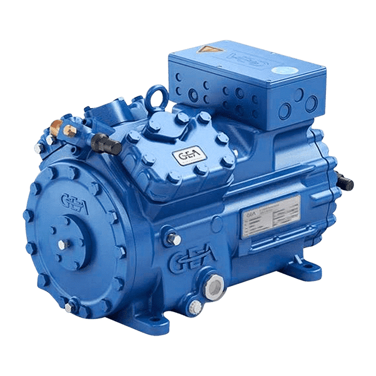
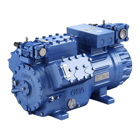
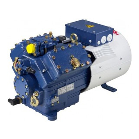
GEA Bock HG34e Series User manual

D
GB
F
E
I
Ru
1
96178-06.2015-DGbFEIRu
engineering for a better world
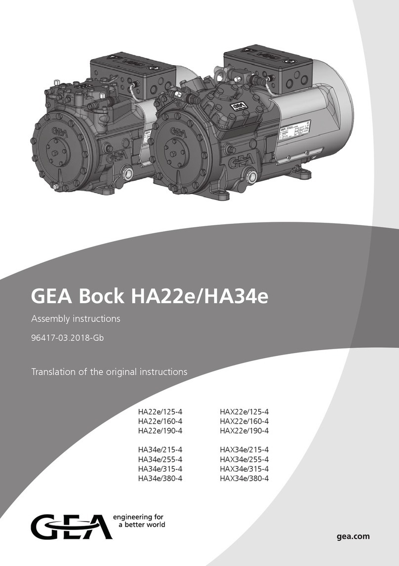
GEA Bock Compressor HG34e
Assembly instructions
HG34e/215-4 HGX34e/215-4 HGX34e/215-4 S R407C
HG34e/255-4 HGX34e/255-4 HGX34e/255-4 S R407C
HG34e/315-4 HGX34e/315-4 HGX34e/315-4 S R407C
HG34e/380-4 HGX34e/380-4 HGX34e/380-4 S R407C
HG34e/215-4 S HGX34e/215-4 S
HG34e/255-4 S HGX34e/255-4 S
HG34e/315-4 S HGX34e/315-4 S
HG34e/380-4 S HGX34e/380-4 S
1
2
3
4
5
6
7
8
9
10
11
12
13

2
D
GB
F
E
I
Ru
96178-06.2015-DGbFEIRu
1 Safety 4
1.1 Identicationofsafetyinstructions
1.2 Qualicationsrequiredofpersonnel
1.3 Generalsafetyinstructions
1.4 Intendeduse
2 Product description 6
2.1 Shortdescription
2.2 Nameplate
2.3 Typekey
About these instructions
Readtheseinstructionsbeforeassemblyandbeforeusingthecompressor.Thiswillavoidmisunder-
standings andpreventdamage.Improperassemblyanduseofthecompressorcanresultinserious
orfatalinjury.
Observethesafetyinstructionscontainedintheseinstructions.
Theseinstructionsmustbepassedontotheendcustomeralongwiththeunitinwhichthecompres-
sorisinstalled.
GEABockGmbH
72636Frickenhausen
GEABockGmbH
Benzstraße7
72636Frickenhausen
Germany
Telephone+49702294540
Fax +4970229454137
www.gea.com
Manufacturer
Contact
Contents Page

D
GB
F
E
I
Ru
3
96178-06.2015-DGbFEIRu
Contents Page
3 Areas of application 8
3.1 Refrigerants
3.2 Oilcharge
3.3 Limitsofapplication
3.4 Refrigerants-designforR407C,35bar
3.5 OilchargeforR407C,35bar
3.6 LimitsofapplicationforR407C,35bar
4Compressor assembly 12
4.1 Storageandtransport
4.2 Settingup
4.3 Pipeconnections
4.4 Pipes
4.5 Layingsuctionandpressurelines
4.6 Operatingtheshut-offvalves
4.7 Operatingmodeofthelockableserviceconnections
5 Electrical connection 15
5.1 Informationforcontactorandmotorcontactorselection
5.2 Connectionofthedrivingmotor
5.3 Circuitdiagramfordirectstart230VΔ/400VY-->with MP10
5.4 ElectronictriggerunitMP10
5.5 ConnectionoftheelectronictriggerunitMP10
5.6 FunctionaltestoftheelectronictriggerunitMP10
5.7 Circuitdiagramfordirectstart230VΔ/400VY-->with INT69 G
5.8 ElectronictriggerunitINT69G
5.9 ConnectionoftheelectronictriggerunitINT69G
5.10 FunctionaltestoftheelectronictriggerunitINT69G
5.11 Startunloader
6 Commissioning 24
6.1 Preparationsforstart-up
6.2 Pressurestrengthtest
6.3 Leaktest
6.4 Evacuation
6.5 Refrigerantcharge
6.6 Start-up
6.7 Avoidingslugging
6.8 Connectionofoillevelregulator
7 Maintenance 26
7.1 Preparation
7.2 Worktobecarriedout
7.3 Sparepartsrecommendation
7.4 Accessories
7.5 Extractfromthelubricantstable
7.6 Decommissioning
8 Technical data 28
9 Dimensions and connections 30
10 Declaration of conformity and installation 32
11 Service 33

4
D
GB
F
E
I
Ru
96178-06.2015-DGbFEIRu
1|Safety
1.2 Qualicationsrequiredofpersonnel
DANGER Indicates a dangerous situation which, if not avoided,
will cause immediate fatal or serious injury.
WARNING Indicates a dangerous situation which, if not avoided,
may cause fatal or serious injury.
CAUTION Indicates a dangerous situation which, if not avoided,
may cause fairly severe or minor injury.
ATTENTION Indicates a situation which, if not avoided,
may cause property damage.
INFO Important information or tips on simplifying work.
WARNING Inadequatelyqualied personnelposesthe riskof accidents,the
consequencebeingseriousorfatalinjury.Workoncompressors
isthereforereservedforpersonnelwhichisqualiedtoworkon
pressurized refrigerant systems:
•For example, a refrigeration technician, refrigeration mechatronic
engineer. As well as professions with comparable training, which
enables personnel to assemble, install, maintain and repair
refrigerationandair-conditioningsystems.Personnelmustbecapable
ofassessingtheworktobecarriedoutandrecognisinganypotential
dangers.
1.1 Identicationofsafetyinstructions:

D
GB
F
E
I
Ru
5
96178-06.2015-DGbFEIRu
1|Safety
1.4 Intended use
1.3 General safety instructions
WARNING Risk of accidents.
Refrigerating compressors are pressurised machines and as such
call for heightened caution and care in handling.
The maximum permissible overpressure must not be exceeded,
even for testing purposes.
Risk of burns!
- Depending on the operating conditions, surface temperatures of
over 60°C on the discharge side or below 0°C on the suction side
can be reached.
- Avoid contact with refrigerant necessarily.
Contact with refrigerant can cause severe burns and skin
damage.
WARNING The compressor may not be used in potentially explosive
environments!
These assembly instructions describe the standard version of the compressor named in the title
manufacturedbyGEA Bock.GEABockrefrigerating compressorsareintended for installationin a
machine(withintheEUaccordingtotheEU Directives 2006/42/EC MachineryDirective,97/23/EC
PressureEquipmentDirectiveand2006/95/EC–LowVoltageDirective).
Commissioningispermissibleonlyifthecompressorhasbeeninstalledinaccordancewiththeseas-
semblyinstructionsandtheentiresystemintowhichitisintegratedhasbeeninspectedandapproved
inaccordancewithlegalregulations.
Thecompressorsareintendedforuseinrefrigerationsystemsincompliancewiththelimitsof
application.
Onlytherefrigerantspeciedintheseinstructionsmaybeused.
Any other use of the compressor is prohibited!

6
D
GB
F
E
I
Ru
96178-06.2015-DGbFEIRu
1
2
3
4
5
6
7
8
9
10
11
12
13
2|Product description
• Semi-hermeticfour-cylinderreciprocatingcompressorwithoilpumplubrication.
• Suctiongascooleddrivemotor.
2.1 Short description
DimensionandconnectionvaluescanbefoundinChapter9
Nameplate
Fig.1
Fig.2
Oilsightglass
Valveplate
Cylindercover
Discharge
shut-offvalve
Oilpump
Terminalbox
Suctionshut-
offvalve
Drivesection
Motorsection
Transporteyelet

D
GB
F
E
I
Ru
7
96178-06.2015-DGbFEIRu
GEA Bock GmbH
72636 Frickenhausen, Germany
2|Product description
2.2 Name plate (example)
1 Typedesignation 6 Voltage,circuit,frequency
2 Machinenumber 7 Nominalrotationspeed
3 maximumoperatingcurrent 8 Displacement
4 Startingcurrent(rotorblocked) 9 Voltage,circuit,frequency
5 NDLP:
max.admissibleoperatingpressur
e 10 Nominalrotationspeed
(g)Lowpressureside 11 Displacement
HD(HP):
max.admissibleoperating
12 Oiltypelledatthefactory
pressur
e(g)Highpressureside 13 Terminalboxprotectiontype
Observe the limits of application Electrical accessories can change
diagrams! the IP protection class!
50 Hz
}
60 Hz
}
/
HG 43 e 380-4 SX
2.3 Type key (example)
¹) HG-HermeticGas-cooled(suctiongas-cooled)
²) X
-Esteroilcharge(HFCrefrigerant,e.g.R134a,R404A/R507,R407C)
3) S - Morepowerfulmotor,e.g.forair-conditioningapplications
1
2
3
4
513
12
7
11
6
10
8
9
19/28 SE 55
27,3
32,8
HGX34e/315-4
21,1/12,2A
111A 64A
IP66
Fig.3
AS38125A001
R407C
Refrigerant
Motorvariant3)
Numberofpoles
Sweptvolume
e-series
Numbersofcylinders
Size
Oilcharge²)
Series¹)

8
D
GB
F
E
I
Ru
96178-06.2015-DGbFEIRu
3|Areas of application
Thecompressorsarelledatthefactorywiththefollowingoiltype:
-forR134a,R404A/R507,R407C FUCHSRenisoTritonSE55
-forR22 FUCHSRenisoSP46
Compressorswithesteroilcharge(FUCHSRenisoTritonSE55)aremarkedwithanXinthetype
designation(e.g.HGX34e/380-4).
3.1 Refrigerants
• HFKW/HFC: R134a,R404A/R507,R407C
• (H)FCKW/(H)CFC: R22
3.2 Oil charge
3.3 Limits of application
INFO For refilling, we recommend the above oil types.
Alternatives: see lubricants table, Chapter 7.5
ATTENTION The oil level must be in the
visible part of the sight glass;
damage to the compressor is
possible if overfilled or under-
filled! Fig.4
max.
min.
0,8Ltr.
oillevel ~
~
ATTENTION Compressor operation is possible within the operating limits
showninthediagrams.Pleasenotethesignicance
of the shaded areas. Thresholds should not be selected as
design or continuous operation points.
- Permissible ambient temperature (-20°C) - (+60°C).
- Max. permissible discharge end temperature 140°C.
-Max.permissibleswitchingfrequency8x/h.
- A minimum running time of 3 min. steady-state condition
(continuous operation) must be achieved.
For operation with supplementary cooling:
- Use only oils with high thermal stability.
- Avoid continuous operation near the threshold.
Foroperationwithfrequencyconverter:
- The maximum current and power consumption must not be
exceeded.Inthecaseofoperationabovethemainsfrequency,the
application limit can therefore be limited.
When operating in the vacuum range, there is a danger of air
entering on the suction side. This can cause chemical reactions,
a pressure rise in the condenser and an elevated compressed-gas
temperature. Prevent the ingress of air at all costs!

D
GB
F
E
I
Ru
9
96178-06.2015-DGbFEIRu
Evaporationtemperature(°C)
Condensingtemperature(°C)
Suctiongassuperheat(K)
Suctiongastemperature(°C)
3|Areas of application
Design for other
areasonrequest
R134a
R407C
R404A/R507
R22
Fig.5
Fig.6
Fig.7
Fig.8
Unlimitedapplicationrange
Supplementarycoolingor
reducedsuctiongastemperature
Supplementarycoolingand
reducedsuctiongastemperature
MotorversionS
(morepowerfulmotor)
Max. permissible operating
pressure (LP/HP)1): 19/28 bar
1) LP=Lowpressure
HP=Highpressure

10
D
GB
F
E
I
Ru
96178-06.2015-DGbFEIRu
D
GB
F
E
7
96157-02.2011-DGbFEI
2|Produktbeschreibung
1
2
3
4
513
12
7
11
6
10
8
9
/
HG 43 e 315- R407C
4 SX
19/35 SE 55
27,3
32,8
1 Typbezeichnung
2 Maschinennummer
3 maximaler Betriebsstrom
4 Anlaufstrom (Rotor blockiert)
5 ND (LP): max. zulässiger Überdruck
Niederdruckseite
HD (HP): max. zulässiger Überdruck
Hochdruckseite
Beachten Sie hierzu die
Einsatzgrenzendiagramme!
50 Hz
60 Hz
6 Spannung, Schaltung, Frequenz
7 Nenndrehzahl
8 Hubvolumen
9 Spannung, Schaltung, Frequenz
10 Nenndrehzahl
11 Hubvolumen
12 Werkseitig eingefüllte Ölsorte
13 Schutzart Klemmenkasten
Elektrisches Zubehör kann die IP-
Schutzklasse verändern!
HGX34e/315-4 S R407C
28,1/16,2A
134A 77A
}
}
Abb. 3
2.2 Typschild (Beispiel)
2.3 Typschlüssel (Beispiel)
¹) HG - Hermetic Gas-Cooled (sauggasgekühlt)
²) X
- Esterölfüllung
3) S - Stärkerer Motor
Kältemittel
Motorvariante 3)
Polzahl
Hubraum
e-Serie
Zylinderzahl
Baugröße
Ölfüllung ²)
Baureihe ¹)
AS38125A001
Thecompressorsarelledatthefactorywiththefollowingoiltype:FUCHSRenisoTritonSE55
Compressorswithesteroilcharge(FUCHSRenisoTritonSE55)aremarkedwithanXinthetype
designation(e.g.HGX34e/380-4R407C).
3.4 Refrigerant - Design for R407C, 35 bar
• HFKW/HFC: R407C
3.5 Oil charge for R407C, 35 bar
3.6 Limits of application for R407C, 35 bar
Only compressors with the additional designation
R407C (see name plate, Fig. 3 and 9)
Fig.9
D
GB
F
E
7
96157-02.2011-DGbFEI
2|Produktbeschreibung
1
2
3
4
513
12
7
11
6
10
8
9
/
HG 43 e 315- R407C
4 SX
19/35 SE 55
27,3
32,8
1 Typbezeichnung
2 Maschinennummer
3 maximaler Betriebsstrom
4 Anlaufstrom (Rotor blockiert)
5 ND (LP): max. zulässiger Überdruck
Niederdruckseite
HD (HP): max. zulässiger Überdruck
Hochdruckseite
Beachten Sie hierzu die
Einsatzgrenzendiagramme!
50 Hz
60 Hz
6 Spannung, Schaltung, Frequenz
7 Nenndrehzahl
8 Hubvolumen
9 Spannung, Schaltung, Frequenz
10 Nenndrehzahl
11 Hubvolumen
12 Werkseitig eingefüllte Ölsorte
13 Schutzart Klemmenkasten
Elektrisches Zubehör kann die IP-
Schutzklasse verändern!
HGX34e/315-4 S R407C
28,1/16,2A
134A 77A
}
}
Abb. 3
2.2 Typschild (Beispiel)
2.3 Typschlüssel (Beispiel)
¹) HG - Hermetic Gas-Cooled (sauggasgekühlt)
²) X
- Esterölfüllung
3) S - Stärkerer Motor
Kältemittel
Motorvariante 3)
Polzahl
Hubraum
e-Serie
Zylinderzahl
Baugröße
Ölfüllung ²)
Baureihe ¹)
AS38125A001
3|Areas of application
ATTENTION Compressor operation is possible within the operating limits
showninthediagrams.Pleasenotethesignicance
of the shaded areas. Thresholds should not be selected as
design or continuous operation points.
- Permissible ambient temperature (-20°C) - (+60°C)
- Max. permissible discharge end temperature 140°C.
-Max.permissibleswitchingfrequency8x/h.
- A minimum running time of 3 min. steady-state condition
(continuous operation) must be achieved.
For operation with supplementary cooling:
- Use only oils with high thermal stability.
- Avoid continuous operation near the threshold.
Foroperationwithfrequencyconverter:
- The maximum current and power consumption must not be
exceeded.Inthecaseofoperationabovethemainsfrequency,the
application limit can therefore be limited.
When operating in the vacuum range, there is a danger of air
entering on the suction side. This can cause chemical reactions,
a pressure rise in the condenser and an elevated compressed-gas
temperature. Prevent the ingress of air at all costs!
INFO For refilling, we recommend the above oil types.
Alternatives: see lubricants table, Chapter 7.5

D
GB
F
E
I
Ru
11
96178-06.2015-DGbFEIRu
3.6 Limits of application for R407C, 35 bar
R407C
Fig.10
Verdampfungstemperatur(°C)
Verüssigungstemperatur(°C)
Sauggastemperatur(°C)
3|Areas of application
Unlimitedapplicationrange
Evaporationtemperature(°C)
Condensingtemperature(°C)
Suctiongastemperature(°C)
Design for other
areasonrequest
Max. permissible operating
pressure (LP/HP)1): 19/35 bar
1) LP=lowpressure
HP=highpressure

12
D
GB
F
E
I
Ru
96178-06.2015-DGbFEIRu
4|Compressor assembly
Setuponanevensurfaceorframewithsufcientload-
bearingcapacity.
Singlecompressorpreferablyonvibrationdamper.
Duplexandparallelcircuitsalwaysrigid.
Provideadequateclearanceformaintenancework.
Ensureadequatecompressorventilation.
Donotuseinacorrosive,dusty,dampatmosphereora
combustibleenvironment.
Fig.13
Fig.14
Fig.15
4.3 Pipe connections
F
E
D
C
B
A
1
2
3
4
F
E
D
C
4
3
2
1
A
B
Tol.-Ang. DIN ISO 2768-mK
Ra Rz
Maß
Passung
Freigabe
Alternativbezug:
Baumustergeprüft
Teil inaktiv
Lieferantenzeichnung
-
-
K.-Auftrag:
PL:
Zeichnung ungültig
Entwicklungsstand
Teil keine Serie
120
400
±0.5
über 0.5
bis 6
Benzstraße 7 - 72636 Frickenhausen - Germany - www.bock.de
-
-
Unbemaßte Radien:
-
Diese Zeichnung ist unser Eigentum!
Sie darf ohne unsere Genehmigung weder nach-
gebildet, vervielfältigt, oder Dritten Personen zu-
gänglich gemacht werden. Der Nachbau nach
dieser Zeichnung, oder an Hand der nach dieser
Zeichnung hergestellten Gegenstände durch den
Abnehmer oder Dritte ist nicht gestattet.
Wir behalten uns alle Rechte, gemäß DIN ISO 16016
an dieser Zeichnung vor.
Bearb.
Datum
Änderungs-Nr.
Werkstoff:
Ausgangsteil, bzw. Rohteil:
--
Gepr.
Name
Datum
19.04.
Werkstückkanten
DIN ISO 13715
Ersatz für:
Ersetzt durch:
Erstellt
2010
Geprüft
-
Kurz
Zone
1/x
Oberflächenbehandlung / Härte:
-
Blatt:
Änderungsbeschreibung
400
Benennung:
±0.8
1000
30
6
-
±0.3
120
30
±0.2
Zeichn.-Nr. Teile-Nr.
Oberflächenangaben ISO 1302
x.xxxx-xxxxx.x
Zust.
Gußtoleranzen:
Gewicht: (kg)
±0.1
Maßstab:
1:1
Wasserwaage
für Indesign
Der Lieferant muß sicherstellen, dass die Ware in
einwandfreiem Zustand angeliefert wird (Korrosions-
schutz, Verpackung für sicheren Transport).
Rz 25
Rz 160
s
25
z
y
x
w
u
t
0,05
Rz 1,6
0,3
0,7
1,6
2
Rz 16
6,3
Rz 63
Rz 6,3
Rz 12,5
F:\user\kurz\3D Sachen\3D Teile\Zeichnungen\Wasserwaage
4.2 Setting up
?
4.1 Storage and transport
Usetransporteyelet.
Donotliftmanually!
Useliftinggear!
Storageat(-30°C)-(+70°C),maximumpermissiblerelativehumidity
10%-95%,nocondensation
Donotstoreinacorrosive,dusty,vaporousatmosphereorinacom-
bustibleenvironment.
Fig.12
Fig.11
INFO Newcompressorsarefactory-lledwithinertgas(3barnitrogen).
Leave this service charge in the compressor for as long as possible
and prevent the ingress of air. Check the compressor for transport
damage before starting any work.
ATTENTION Attachments (e.g. pipe holders, additional units, fastening parts,
etc.) directly to the compressor are not permissible!
ATTENTION Damage possible.
Do not solder as long as the compressor is under pressure.
Superheating can damage the valve. Remove the pipe supports
therefore from the valve for soldering and accordingly cool the
valve body during and after soldering.
Only solder using inert gas to inhibit oxidation products (scale).

D
GB
F
E
I
Ru
13
96178-06.2015-DGbFEIRu
1
2
3
4
5
6
7
8
9
10
11
12
13
4|Compressor assembly
4.4 Pipes
Pipesandsystemcomponentsmustbecleananddryinsideandfreeofscale,swarfandlayersof
rustandphosphate.Onlyuseair-tightparts.
Lay pipes correctly. Suitable vibration compensators must be provided to prevent pipes being
crackedandbrokenbyseverevibrations.
Ensureaproperoilreturn.
Keeppressurelossestoanabsoluteminimum.
The pipe connectionshavegraduatedinsidediameterssothatpipeswith
standartmillimetreandinchdimensionscanbeused.
Theconnectiondiametersoftheshut-offvalvesareratedformaximum
compressoroutput.Theactualrequiredpipecrosssectionmustbe
matched to the output. The same applies for non-return valves.
Fig.16:graduated
internaldiameter
Fig.17
Rigid
fixed point
As short as
possible
4.5 Laying suction and pressure lines
A rule of thumb:Alwayslaytherstpipesectionstartingfromtheshut-offvalvedownwards and
parallel to the drive shaft.
ATTENTION Improperly installed pipes can cause cracks and tears, the result
being a loss of refrigerant.
INFO Proper layout of the suction and discharge lines directly after
the compressor is integral to the system’s smooth running and
vibration behaviour.

14
D
GB
F
E
I
Ru
96178-06.2015-DGbFEIRu
4|Compressor assembly
4.6 Operating the shut-off valves
Beforeopeningorclosingtheshut-offvalve,releasethevalvespindlesealbyapprox.¼ofaturn
counter-clockwise.
Afteractivatingtheshut-offvalve,re-tightentheadjustablevalvespindlesealclockwise.
Pipeconnection
Pipeconnection
4.7 Operating mode of the lockable service connections
Fig.20
Opening the shut-off valve:
Spindle:turntotheleft(counter-clockwise)asfarasitwillgo.
—>Shut-offvalvecompletelyopened/serviceconnectionclosed.
Fig.21
Opening the service connection
Spindle:Turn½-1turntotherightclockwise.
—>Serviceconnectionopened/shut-offvalveopened.
Serviceconnec-
tionclosed
Connection
blocked
Spindle
Serviceconnec-
tionopened
Spindle Connection
open
Compressor
Compressor
Fig.18 Fig.19
Valve spindle seal
Release
Tighten

D
GB
F
E
I
Ru
15
96178-06.2015-DGbFEIRu
5|Electrical connection
5.1 Information for contactor and motor contactor selection
Allprotectiondevicesandswitchingormonitoringunitsmustbettedinaccordancewiththelocal
safetyregulationsandestablishedspecications(e.g.VDE)aswellaswiththemanufacturer’sinfor-
mation. Motor protection switches are required! Motor contactors, feed lines, fuses and motor
protectionswitchesmustberatedonthebasisofthemaximumworkingcurrent(seenameplate).
Formotorprotectionuseacurrent-dependentandtime-delayedoverloadprotectiondeviceformoni-
toringallthreephases.Settheoverloadprotectiondevicesothatitmustbeactuatedwithin2hours,
ifthereis1.2timesthemax.workingcurrent.
5.2 Connection of the driving motor
Thecompressorisdesignedwithamotorforstar-deltacircuits.
Designationonthenameplate Stickerontheterminalbox
∆/ Y
Star-delta start-up is only possible on 230 V voltage supply. Example:
230 V ∆
Direct start Star-delta start
400 V Y
Direct start only
Elektrischer Anschluss
Electrical connection
Raccordement électrique ∆/ Y
96027-11.06-DGbF
∆
Niedere Spannung
Low voltage
Bas voltage
Y
Hohe Spannung
High voltage
Haut voltage
L3
L1 L2
L3
L1 L2
Elektrischer Anschluss
Electrical connection
Raccordement électrique ∆/ Y
96027-11.06-DGbF
∆
Niedere Spannung
Low voltage
Bas voltage
Y
Hohe Spannung
High voltage
Haut voltage
L3
L1 L2
L3
L1 L2
L1 L2 L3
L1 L2 L3
INFO Connectthecompressormotorinaccordancewiththecircuitdiagram
(seeinsideofterminalbox).
Usesuitablecableentrypointofthecorrectprotectiontype(see
nameplate)forroutingcablesintotheterminalbox.Insertthestrain
reliefsandpreventchafemarksonthecables.
Comparethevoltageandfrequencyvalueswiththedataforthe
mainspowersupply.
Only connect the motor if these values are the same.
DANGER Risk of electric shock! High voltage!
Only carry out work when the electrical system is disconnected
from the power supply!
5 Electrical connection
INFO The connection examples shown refer to the standard version. In
thecaseofspecialvoltages,theinstructionsafxedtotheterminal
box apply.

16
D
GB
F
E
I
Ru
96178-06.2015-DGbFEIRu
5.3 Circuit diagramm for direct start 230 V ∆/ 400 V Y --> compressor with MP10
BT1 Coldconductor(PTCsensor)motorwinding
BT2 Thermalprotectionthermostat(PTCsensor)
FC1 Loadcircuitsafetyswitches
FC2 Controlpowercircuitfuse
BP1 Safetychain(high/lowpressuremonitoring)
BP2 Releaseswitch(thermostat/pressostat)
01234
56789
Urspr.
Ers.f.
Ers.d.
Anlagenbezeichnung
Οnderung
Vorblatt:
Datum
1
Name
Bearb.
Gepr.
Norm
HG34P
R410A/Co2
200308
Kommission:
Gesamtblatt:
Datum
27.05.2015
27.05.2015
11
Kelich
Name
Zeichnungsnummer:
Kundennummer:
Kunde:
Anlage
Bl. Gruppe:
=
2INT69_24V
Ort
Bl.
Fbl.
+
1 (ohne HA)
2HG34 FU+Box
27.05.2015ESSG_A1_35_01D
Klemmenkasten Verdichter
MP10
A1 Alarm Motorschutz
A2 Übertemperatur BT1, BT2
A3 Alarm Hochdruck
BT1
QA1
FC1
I> I>
I>
QA2
PE
FC1
A1
X1 L1 L1 N N 43 43 11 12 14
L S M
X2123456
FC2
SF1
BT2
A2
BP1
P
PE
A3
BP2
P<
PE
QA2
12
EB1
QA2
3 4
L1.1
L2.1
L3.1
L1.2
N
PE
-EC1 3~
M
Θ
L1 L2 L3 N PE
Compressorterminalbox
Fig.22

D
GB
F
E
I
Ru
17
96178-06.2015-DGbFEIRu
QA1 Mainswitch
SF1 Controlvoltageswitch
EC1 Compressormotor
QA2 Compressorcontactor
MP10 ElectronictriggerunitMP10
EB1 Oilsumpheater
01234
56789
Urspr.
Ers.f.
Ers.d.
Anlagenbezeichnung
Οnderung
Vorblatt:
Datum
1
Name
Bearb.
Gepr.
Norm
HG34P
R410A/Co2
200308
Kommission:
Gesamtblatt:
Datum
27.05.2015
27.05.2015
11
Kelich
Name
Zeichnungsnummer:
Kundennummer:
Kunde:
Anlage
Bl. Gruppe:
=
2INT69_24V
Ort
Bl.
Fbl.
+
1 (ohne HA)
2HG34 FU+Box
27.05.2015ESSG_A1_35_01D
Klemmenkasten Verdichter
MP10
A1 Alarm Motorschutz
A2 Übertemperatur BT1, BT2
A3 Alarm Hochdruck
BT1
QA1
FC1
I> I>
I>
QA2
PE
FC1
A1
X1 L1 L1 N N 43 43 11 12 14
L S M
X2123456
FC2
SF1
BT2
A2
BP1
P
PE
A3
BP2
P<
PE
QA2
1 2
EB1
QA2
3 4
L1.1
L2.1
L3.1
L1.2
N
PE
-EC1 3~
M
Θ
L1 L2 L3 N PE
A1 Alarmmotorprotection
A2 OverheatingBT1,BT2
A3 Alarmhighpressure

18
D
GB
F
E
I
Ru
96178-06.2015-DGbFEIRu
5|Electrical connection
PTC1 PTC2
Terminalbox
Fig.23
5.4 Electronic trigger unit MP10
Thecompressormotoristtedwithcoldconductortemperaturesensors(PTC)connectedtotheelec-
tronictriggerunitMP10intheterminalbox.ReadinesstooperateissignalledbytheH3LED(green)
afterthepowersupplyisapplied.Inthecaseofexcesstemperatureinthemotorwinding,theunit
switchesoffthecompressorandtheH1LEDlightsred.
Thehotgassideofthecompressorcanalsobeprotectedagainstovertemperatureusingathermal
protectionthermostat(accessory).TheH2LED(red)isprovidedfortheprotectionfunction.
The unit trips when an overload or inadmissible operating conditions occur. Find and remedy
the cause.
5.5 Connection of the trigger unit MP10
Temperaturemonitoringconnections:
Motorwinding: Terminals1-2
Thermalprotectionthermostat: Terminals3-4
Restartprevention: Terminals5-6
INFO
Theunithasarestartpreventiondevice.Afteryouhaverectiedthe
fault, interrupt the mains voltage. This unlocks the restart prevention
device and the LEDs H1 and H2 go out.
INFO Connect the trigger unit MP10 in accordance with the circuit dia-
gram. Protect the trigger unit with a delayed-action fuse (FC2) of
max. 4 A. In order to guarantee the protection function, install the
triggerunitastherstelementinthecontrolpowercircuit.
ATTENTION
Terminals 1 - 6 on the trigger
unit MP10 and terminals PTC 1
and PTC 2 on the compressor
terminal board must not come
into contact with mains voltage.
This would destroy the trigger
unit and PTC sensors.
The supply voltage at L1-N (+/-
for DC 24 V version) must be
identical to the voltage at termi-
nals 11, 12, 14 and 43.

D
GB
F
E
I
Ru
19
96178-06.2015-DGbFEIRu
5|Electrical connection
ThecompressorandthetriggerunitMP10areoperationalwhentheH3LED(green)lights.
5.6 Function test of the trigger unit MP10
Pos Procedure LED H1 LED H2 LED H3
red red green
1•Interrupt power supply (L1 or SF1) OFF OFF OFF
•Releasethemotortemperaturesensorconnection(1or2)
•Releasethehotgastemperaturesensor(ifinstalled)(3or4)
2•Restore the power supply (L1 or SF1) ON
•Functioncheckofmotortemperaturesensor:operational ON
•Functioncheckofhotgastemperaturesensor:operational ON
3•Interrupt power supply again (L1 or SF1) OFF OFF OFF
•Reconnectterminals1or2and/or3or4
4•Restore the power supply (L1 or SF1): OFF OFF ON
•MP10isoperationalagain
Beforestart-up,troubleshootingormakingchangestothecontrolpowercircuit,checkthefunctionality
ofthetriggerunit:

20
D
GB
F
E
I
Ru
96178-06.2015-DGbFEIRu
01234
56789
Urspr.
Ers.f.
Ers.d.
Anlagenbezeichnung
Οnderung
Vorblatt:
Datum
2INT69
Name
Bearb.
Gepr.
Norm
HG34P
R410A/Co2
200308
Kommission:
Gesamtblatt:
Datum
27.05.2015
27.05.2015
11
Kelich
Name
Zeichnungsnummer:
Kundennummer:
Kunde:
Anlage
Bl. Gruppe:
=
2INT69_24V
Ort
Bl.
Fbl.
+
2INT69 (Ohne HA)
2INT69HR60
27.05.2015ESSG_A1_35_01D
Klemmenkasten Verdichter
A1 Alarm Motorschutz
A2 Übertemperatur BT1, BT2
A3 Alarm Hochdruck
INT69 G
BT1
QA1
FC1
I> I>
I>
QA2
PE
FC1
A1
FC2
SF1
A2
BP1
P
PE
A3
BP2
P<
PE
QA2
12
EB1
QA2
3 4
L1
L2
L3
L1.1
N
PE
1112 14
L N B1 B2
-EC1 3~
M
Θ
BT2
L1 L2 L3 N PE
5.7 Circuit diagramm for direct start 230 V ∆/ 400 V Y --> compressor with INT69 G
Fig.24
BT1 Coldconductor(PTCsensor)motorwinding
BT2 Thermalprotectionthermostat(PTCsensor)
FC1 Loadcircuitsafetyswitches
FC2 Controlpowercircuitfuse
BP1 Safetychain(high/lowpressuremonitoring)
BP2 Releaseswitch(thermostat/pressostat)
Compressorterminalbox
This manual suits for next models
20
Table of contents
Other GEA Bock Air Compressor manuals

GEA Bock
GEA Bock EX-HG66e Series User manual

GEA Bock
GEA Bock HGZ7 Series User manual

GEA Bock
GEA Bock HA6 User manual

GEA Bock
GEA Bock IN Touch HAX2/70-4 CO2 T User manual

GEA Bock
GEA Bock In Touch HA4/310-4 User manual

GEA Bock
GEA Bock HG12P/75-4 User manual

GEA Bock
GEA Bock Bock HA5 User manual

GEA Bock
GEA Bock HA12P User manual

GEA Bock
GEA Bock HGX44e CO2 Series User manual

GEA Bock
GEA Bock HG22e Series User manual