7
09665-01.2019-Gb
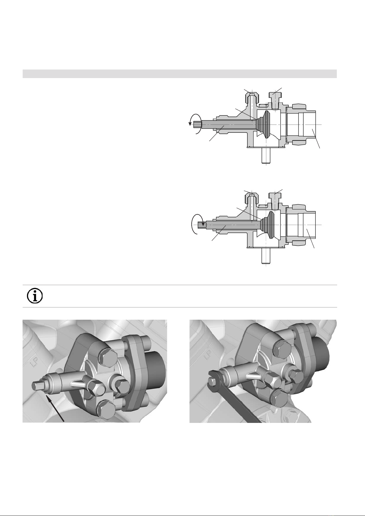
Shaft end Leak oil drain hose
Dimensions in mm
8x M8 72
130
6x M8
A5x9 DIN 6888
1:5
110
98
50
90
100
54
2
40
74
M12x28
66
z
Alt.bezug /
F
E
D
C
A
F
E
D
C
41
A
B
5
6
7
8
1
2
34
5
6
7
über / above
bis / up to
Numéro de plan:
B
32
088314
8
Freigabe / Approved
Extranet:
B
-
Alt.supply:
Maßstab /
Der Lieferant muss sicherstellen, dass die Ware
in einwandfreiem Zustand angeliefert wird
(Korrosionsschutz, Verpackung für sicheren
Ra Rz
Allgemeintoleranzen / General tolerances
Drawing-No.
Zeichn.-Nr. / Drawing no. /
Dok-ID:
±0.1
yxw uts
packaging for safe transportation).
model or design.
in proper conditions (corrosion prevention,
DIN ISO 2768-mK
Ersatz für / replacement for:
The supplier has to ensure the delivery of parts
Transport).
prohibited. Offenders will be held liable for the Dimension Passung / Clearance
Baumustergeprüft / Type examination:
--
K.-Auftrag / C.-Task:
Projektleiter / Project leader:
120
400
±0.5
0.5
6
GEA Bock GmbH - Benzstraße 7 - 72636 Frickenhausen - Germany - www.bock.de
-
-
-
Unbemaßte Radien / Undimensioned radii:
-
Bearb. / EditedDatum / Date
payment of damages. All rights reserved in the event Änd.-Nr. / Mod-No.
Werkstoff (Zeile 2+3 alternativ) /
Base part, Raw part:
-
-
Geprüft / Appr.
NameDatum / Date
27.07.07
Material (Line 2+3 alternative):
Ausgangsteil, Rohteil /
Workpiece edges
DIN ISO 13715
Erstellt / Drawn
Geprüft / Verified Schaich
Schnizler
1/3
Oberflächenbehandlung, Härte / Treatment of surface, Hardness:
27.02.08
Werkstückkanten /
Page:
400 Benennung / Description:
±0.8
1000
306
31,2
±0.3
12030
-
Blatt /
±0.2
of the grant of a patent, utility /
DIN EN ISO 1302
Zust. / Rev.
Gußtoleranzen / General casting tolerances:
Gewicht / Weight: (kg)
Zeichnungs-Nr. /
Indication of surface texture
Scale:
%
C - FK40/655 N
Rz 25
Rz 160
25 0,05 Rz 1,6
0,3
0,7
1,6
2Rz 16
6,3 Rz 63 Rz 6,3
Rz 12,5 Status:
-
-
in Bearbeitung (CAD)
Nein / No 13983 .0
19.04.12
10.08.12
26.02.13
Gneiting
Gneiting
Zuder
0d | Betrifft Blatt 3
0e | Extranet B hinzugefügt, Ansicht Sickenrichtung hinzugefügt (Bl.2)
0f | Gussänderungen, Betrifft Blatt 2
8251
8266 + 8351
8510,8640
Layh
Schaich
Schaich
K - FK40/655 N
-
08511.
Kunde / Customer:
-
Weitergabe sowie Vervielfältigung dieses Dokuments,
Verwertung und Mitteilung seines Inhalts sind ver-
boten, soweit nicht ausdrücklich gestattet. Zuwider-
handlungen verpflichten zu Schadenersatz. Alle
Rechte für den Fall der Patent-, Gebrauchsmuster-
oder Geschmacksmustereintragung vorbehalten.
The reproduction, distribution and utilization of this
document as well as the communication of its
contents to others without express authorization is
Maß
Oberflächenangaben /
Teile-Nr. /
Part-No.
( ) K Ausführung
Fahrzeugverdichter / Vehicle Compressor / Compresseur pour automobiles
( ) K version Dimensions in mm
Cotes en mm
Maße in mmÄnderungen vorbehalten
Subject to change without notice
Sous réserve de toutes modifications
Sight glass
( ) Version K
1.0851-13983.0 0f
SchauglasK
1) = Ne possible qu 'ex usine
(L)* = Raccord à braser
1) = Only possible ex factory
(L)* = Brazing connection
L
1) = Nur ab Werk möglich
Raccord opt. vanne d'arrêt d'aspiration
Anschluß Wärmeschutzthermostat Connection thermal protection thermostat 2 x 1 1/8 “ – 18 UNEF
Raccord de thermostat de protection thermique
Voyant Zoll
(L)* = Lötanschluß
Zoll
Massenschwerpunkt
-
1/8“ NPTF
M
Centre of gravity
Ölsieb Oil filter Filtre à huile mm M22x1,5
SV1 Opt. Anschlußmöglichkeit Saugabsperrventil
Centre de gravité
-Opt. connection suction line valve
Anschlüsse Connections Raccords FK(X)40/390 FK(X)40/470 FK(X)40/560 FK(X)40/655
SV Saugabsperrventil, Rohr (L)* Suction line valve, tube (L)* Vanne d’arrêt d’aspiration, de tuyau (L)* mm-Zoll 28 – 1 1/8 “ 35 – 1 3/8 “ 35 – 1 3/8 “ 35 – 1 3/8 “
DV Druckabsperrventil, Rohr (L)* Discharge line valve, tube (L)* Vanne d’arrêt de refoulement, de tuyau (L)* mm-Zoll 22 – 7/8 “ 28 – 1 1/8 “ 28 – 1 1/8 “ 35 – 1 3/8 “
A Anschluß Saugseite, nicht absperrbar Connection suction side, not lockable Raccord côté aspiration, non obturable Zoll 1/8“ NPTF
A1 Anschluß Saugseite, absperrbar Connection suction side, lockable Raccord côté aspiration, obturable Zoll 7/16“ UNF
B Anschluß Druckseite, nicht absperrbar Connection discharge side, not lockable Raccord côté refoulement, non obturable Zoll 1/8“ NPTF
B1 Anschluß Druckseite, absperrbar Connection discharge side, lockable Raccord côté refoulement, obturable Zoll 7/16“ UNF
C Anschluß Öldrucksicherheitsschalter OIL Connection oil pressure safety switch OIL Raccord pressostat de sécurité d’huile OIL Zoll 1/8“ NPTF
D Anschluß Öldrucksicherheitsschalter LP Connection oil pressure safety switch LP Raccord pressostat de sécurité d’huile LP Zoll 1/8“ NPTF
E Anschluß Öldruckmanometer Connection oil pressure gauge Raccord du manomètre de pression d’huile Zoll 1/8“ NPTF
F Ölablaß Oil drain Vidange d’huile Zoll 1/4“ NPTF
G Opt. Anschlußmöglichkeit Ölsumpfheizung 1) Opt. connection oil sump heater 1) Raccord opt. chauffage de carter d'huile 1) - -
H Stopfen Ölfüllung Oil charge plug Bouchon de remplissage d’huile Zoll 1/4“ NPTF
Typ / type Teile Nr. / part no. Typ / type Teile Nr. / part no. Typ / type Teile Nr. / part no.
FK(X)40/390 N 13977 (13985) FK(X)40/390 K 13978 (13986) FK(X)40/390 TK 14339 (14343)
FK(X)40/470 N 13979 (13987) FK(X)40/470 K 13980 (13988) FK(X)40/470 TK 14340 (14344)
FK(X)40/560 N 13981 (13989) FK(X)40/560 K 13982 (13990) FK(X)40/560 TK 14341 (14345)
FK(X)40/655 N 13983 (13991) FK(X)40/655 K 13984 (13992) FK(X)40/655 TK 14342 (14346)
F
DV BB1
L
H
K
D
Y
130
108,5
253
4xM10x21 LK 170
344
ca.385
Y
Lecköl-Ablass Schlauch
Leak oil drain hose
Tuyau d'évacuation d'huile de fuite
A1
C/E
SV
M
A
SV1
G210
ca.370
145
4x 13
329
232
ca.319 (325)
ca.50
168,5
ca.170
8x M8 72
130
6x M8
A5x9 DIN 6888
1:5
110
98
h8
50
90
100
148
54
2
40
74
M12x28
66
z
Alt.bezug /
F
E
D
C
A
F
E
D
C
41
A
B
5
6
7
8
1
2
34
5
6
7
über / above
bis / up to
Numéro de plan:
B
32
088314
8
Freigabe / Approved
Extranet:
B
-
Alt.supply:
Maßstab /
Der Lieferant muss sicherstellen, dass die Ware
in einwandfreiem Zustand angeliefert wird
(Korrosionsschutz, Verpackung für sicheren
Ra Rz
Allgemeintoleranzen / General tolerances
Drawing-No.
Zeichn.-Nr. / Drawing no. /
Dok-ID:
±0.1
yxwuts
packaging for safe transportation).
model or design.
in proper conditions (corrosion prevention,
DIN ISO 2768-mK
Ersatz für / replacement for:
The supplier has to ensure the delivery of parts
Transport).
prohibited. Offenders will be held liable for the Dimension Passung / Clearance
Baumustergeprüft / Type examination:
--
K.-Auftrag / C.-Task:
Projektleiter / Project leader:
120
400
±0.5
0.5
6
GEA Bock GmbH - Benzstraße 7 - 72636 Frickenhausen - Germany - www.bock.de
-
-
-
Unbemaßte Radien / Undimensioned radii:
-
Bearb. / EditedDatum / Date
payment of damages. All rights reserved in the event Änd.-Nr. / Mod-No.
Werkstoff (Zeile 2+3 alternativ) /
Base part, Raw part:
-
-
Geprüft / Appr.
NameDatum / Date
27.07.07
Material (Line 2+3 alternative):
Ausgangsteil, Rohteil /
Workpiece edges
DIN ISO 13715
Erstellt / Drawn
Geprüft / Verified Schaich
Schnizler
1/3
Oberflächenbehandlung, Härte / Treatment of surface, Hardness:
27.02.08
Werkstückkanten /
Page:
400 Benennung / Description:
±0.8
1000
306
31,2
±0.3
12030
-
Blatt /
±0.2
of the grant of a patent, utility /
DIN EN ISO 1302
Zust. / Rev.
Gußtoleranzen / General casting tolerances:
Gewicht / Weight: (kg)
Zeichnungs-Nr. /
Indication of surface texture
Scale:
%
C - FK40/655 N
Rz 25
Rz 160
25 0,05 Rz 1,6
0,3
0,7
1,6
2Rz 16
6,3 Rz 63 Rz 6,3
Rz 12,5 Status:
-
-
in Bearbeitung (CAD)
Nein / No 13983 .0
19.04.12
10.08.12
26.02.13
Gneiting
Gneiting
Zuder
0d | Betrifft Blatt 3
0e | Extranet B hinzugefügt, Ansicht Sickenrichtung hinzugefügt (Bl.2)
0f | Gussänderungen, Betrifft Blatt 2
8251
8266 + 8351
8510,8640
Layh
Schaich
Schaich
K - FK40/655 N
-
08511.
Kunde / Customer:
-
Weitergabe sowie Vervielfältigung dieses Dokuments,
Verwertung und Mitteilung seines Inhalts sind ver-
boten, soweit nicht ausdrücklich gestattet. Zuwider-
handlungen verpflichten zu Schadenersatz. Alle
Rechte für den Fall der Patent-, Gebrauchsmuster-
oder Geschmacksmustereintragung vorbehalten.
The reproduction, distribution and utilization of this
document as well as the communication of its
contents to others without express authorization is
Maß
Oberflächenangaben /
Teile-Nr. /
Part-No.
( ) K Ausführung
Fahrzeugverdichter / Vehicle Compressor / Compresseur pour automobiles
( ) K version Dimensions in mm
Cotes en mm
Maße in mmÄnderungen vorbehalten
Subject to change without notice
Sous réserve de toutes modifications
Sight glass
( ) Version K
1.0851-13983.0 0f
SchauglasK
1) = Ne possible qu 'ex usine
(L)* = Raccord à braser
1) = Only possible ex factory
(L)* = Brazing connection
L
1) = Nur ab Werk möglich
Raccord opt. vanne d'arrêt d'aspiration
Anschluß Wärmeschutzthermostat Connection thermal protection thermostat 2 x 1 1/8 “ – 18 UNEF
Raccord de thermostat de protection thermique
Voyant Zoll
(L)* = Lötanschluß
Zoll
Massenschwerpunkt
-
1/8“ NPTF
M
Centre of gravity
Ölsieb Oil filter Filtre à huile mm M22x1,5
SV1 Opt. Anschlußmöglichkeit Saugabsperrventil
Centre de gravité
-Opt. connection suction line valve
Anschlüsse Connections Raccords FK(X)40/390 FK(X)40/470 FK(X)40/560 FK(X)40/655
SV Saugabsperrventil, Rohr (L)* Suction line valve, tube (L)* Vanne d’arrêt d’aspiration, de tuyau (L)* mm-Zoll 28 – 1 1/8 “ 35 – 1 3/8 “ 35 – 1 3/8 “ 35 – 1 3/8 “
DV Druckabsperrventil, Rohr (L)* Discharge line valve, tube (L)* Vanne d’arrêt de refoulement, de tuyau (L)* mm-Zoll 22 – 7/8 “ 28 – 1 1/8 “ 28 – 1 1/8 “ 35 – 1 3/8 “
A Anschluß Saugseite, nicht absperrbar Connection suction side, not lockable Raccord côté aspiration, non obturable Zoll 1/8“ NPTF
A1 Anschluß Saugseite, absperrbar Connection suction side, lockable Raccord côté aspiration, obturable Zoll 7/16“ UNF
B Anschluß Druckseite, nicht absperrbar Connection discharge side, not lockable Raccord côté refoulement, non obturable Zoll 1/8“ NPTF
B1 Anschluß Druckseite, absperrbar Connection discharge side, lockable Raccord côté refoulement, obturable Zoll 7/16“ UNF
C Anschluß Öldrucksicherheitsschalter OIL Connection oil pressure safety switch OIL Raccord pressostat de sécurité d’huile OIL Zoll 1/8“ NPTF
D Anschluß Öldrucksicherheitsschalter LP Connection oil pressure safety switch LP Raccord pressostat de sécurité d’huile LP Zoll 1/8“ NPTF
E Anschluß Öldruckmanometer Connection oil pressure gauge Raccord du manomètre de pression d’huile Zoll 1/8“ NPTF
F Ölablaß Oil drain Vidange d’huile Zoll 1/4“ NPTF
G Opt. Anschlußmöglichkeit Ölsumpfheizung 1) Opt. connection oil sump heater 1) Raccord opt. chauffage de carter d'huile 1) - -
H Stopfen Ölfüllung Oil charge plug Bouchon de remplissage d’huile Zoll 1/4“ NPTF
Typ / type Teile Nr. / part no. Typ / type Teile Nr. / part no. Typ / type Teile Nr. / part no.
FK(X)40/390 N 13977 (13985) FK(X)40/390 K 13978 (13986) FK(X)40/390 TK 14339 (14343)
FK(X)40/470 N 13979 (13987) FK(X)40/470 K 13980 (13988) FK(X)40/470 TK 14340 (14344)
FK(X)40/560 N 13981 (13989) FK(X)40/560 K 13982 (13990) FK(X)40/560 TK 14341 (14345)
FK(X)40/655 N 13983 (13991) FK(X)40/655 K 13984 (13992) FK(X)40/655 TK 14342 (14346)
F
DV BB1
L
H
K
D
Y
130
108,5
253
4xM10x21 LK 170
344
ca.385
Y
Lecköl-Ablass Schlauch
Leak oil drain hose
Tuyau d'évacuation d'huile de fuite
A1
C/E
SV
M
A
SV1
G210
ca.370
145
4x 13
329
232
ca.319 (325)
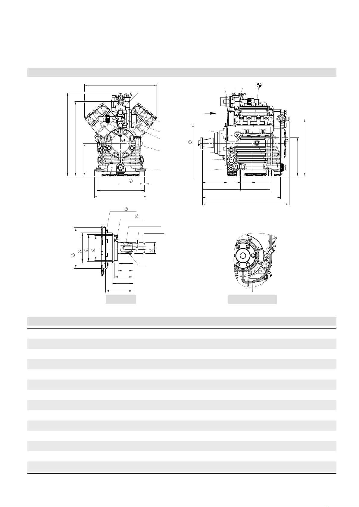
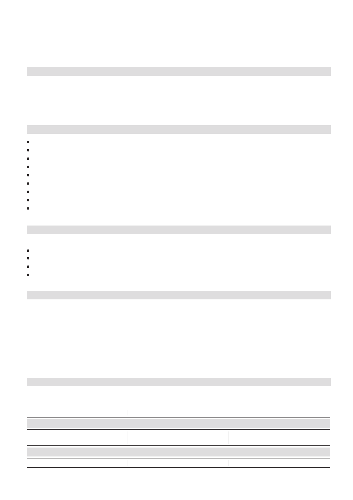
3 I Product description
Dimension drawing
Connections
A Connection suction side, not lockable 1/8“ NPTF
A1 Connection suction side, lockable 7/16“ UNF
B Connection discharge side, not lockable 1/8“ NPTF
B1 Connection discharge side, lockable 7/16“ UNF
C Connection oil pressure safety switch OIL 1/8“ NPTF
D Connection oil pressure safety switch LP 1/8“ NPTF
E Connection oil pressure gauge 1/8“ NPTF
F Oil drain 1/4“ NPTF
G Opt. connection for oil sump heater 1) - -
H Oil charge plug 1/4“ NPTF
K Sight glass 2 x 1 1/8“ NPTF
L Connection thermal protection thermostat 1/8“ NPTF
MOil lter M22x1.5
SV1 Optional connection for suction line valve - -
1) = No connection available as standard.
Available on request (Connection M22 x 1,5)
ca.50
168,5
ca.170
8x M8 72
130
6x M8
A5x9 DIN 6888
1:5
110
98
h8
50
90
100
148
54
2
40
74
M12x28
66
z
Alt.bezug /
F
E
D
C
A
F
E
D
C
41
A
B
5
6
7
8
1
2
34
5
6
7
über / above
bis / up to
Numéro de plan:
B
32
088314
8
Freigabe / Approved
Extranet:
B
-
Alt.supply:
Maßstab /
Der Lieferant muss sicherstellen, dass die Ware
in einwandfreiem Zustand angeliefert wird
(Korrosionsschutz, Verpackung für sicheren
Ra Rz
Allgemeintoleranzen / General tolerances
Drawing-No.
Zeichn.-Nr. / Drawing no. /
Dok-ID:
±0.1
yxw uts
packaging for safe transportation).
model or design.
in proper conditions (corrosion prevention,
DIN ISO 2768-mK
Ersatz für / replacement for:
The supplier has to ensure the delivery of parts
Transport).
prohibited. Offenders will be held liable for the Dimension Passung / Clearance
Baumustergeprüft / Type examination:
--
K.-Auftrag / C.-Task:
Projektleiter / Project leader:
120
400
±0.5
0.5
6
GEA Bock GmbH - Benzstraße 7 - 72636 Frickenhausen - Germany - www.bock.de
-
-
-
Unbemaßte Radien / Undimensioned radii:
-
Bearb. / EditedDatum / Date
payment of damages. All rights reserved in the event Änd.-Nr. / Mod-No.
Werkstoff (Zeile 2+3 alternativ) /
Base part, Raw part:
-
-
Geprüft / Appr.
NameDatum / Date
27.07.07
Material (Line 2+3 alternative):
Ausgangsteil, Rohteil /
Workpiece edges
DIN ISO 13715
Erstellt / Drawn
Geprüft / Verified Schaich
Schnizler
1/3
Oberflächenbehandlung, Härte / Treatment of surface, Hardness:
27.02.08
Werkstückkanten /
Page:
400 Benennung / Description:
±0.8
1000
306
31,2
±0.3
12030
-
Blatt /
±0.2
of the grant of a patent, utility /
DIN EN ISO 1302
Zust. / Rev.
Gußtoleranzen / General casting tolerances:
Gewicht / Weight: (kg)
Zeichnungs-Nr. /
Indication of surface texture
Scale:
%
C - FK40/655 N
Rz 25
Rz 160
25 0,05 Rz 1,6
0,3
0,7
1,6
2Rz 16
6,3 Rz 63 Rz 6,3
Rz 12,5 Status:
-
-
in Bearbeitung (CAD)
Nein / No 13983 .0
19.04.12
10.08.12
26.02.13
Gneiting
Gneiting
Zuder
0d | Betrifft Blatt 3
0e | Extranet B hinzugefügt, Ansicht Sickenrichtung hinzugefügt (Bl.2)
0f | Gussänderungen, Betrifft Blatt 2
8251
8266 + 8351
8510,8640
Layh
Schaich
Schaich
K - FK40/655 N
-
08511.
Kunde / Customer:
-
Weitergabe sowie Vervielfältigung dieses Dokuments,
Verwertung und Mitteilung seines Inhalts sind ver-
boten, soweit nicht ausdrücklich gestattet. Zuwider-
handlungen verpflichten zu Schadenersatz. Alle
Rechte für den Fall der Patent-, Gebrauchsmuster-
oder Geschmacksmustereintragung vorbehalten.
The reproduction, distribution and utilization of this
document as well as the communication of its
contents to others without express authorization is
Maß
Oberflächenangaben /
Teile-Nr. /
Part-No.
( ) K Ausführung
Fahrzeugverdichter / Vehicle Compressor / Compresseur pour automobiles
( ) K version Dimensions in mm
Cotes en mm
Maße in mmÄnderungen vorbehalten
Subject to change without notice
Sous réserve de toutes modifications
Sight glass
( ) Version K
1.0851-13983.0 0f
SchauglasK
1) = Ne possible qu 'ex usine
(L)* = Raccord à braser
1) = Only possible ex factory
(L)* = Brazing connection
L
1) = Nur ab Werk möglich
Raccord opt. vanne d'arrêt d'aspiration
Anschluß Wärmeschutzthermostat Connection thermal protection thermostat 2 x 1 1/8 “ – 18 UNEF
Raccord de thermostat de protection thermique
Voyant Zoll
(L)* = Lötanschluß
Zoll
Massenschwerpunkt
-
1/8“ NPTF
M
Centre of gravity
Ölsieb Oil filter Filtre à huile mm M22x1,5
SV1 Opt. Anschlußmöglichkeit Saugabsperrventil
Centre de gravité
-Opt. connection suction line valve
Anschlüsse Connections Raccords FK(X)40/390 FK(X)40/470 FK(X)40/560 FK(X)40/655
SV Saugabsperrventil, Rohr (L)* Suction line valve, tube (L)* Vanne d’arrêt d’aspiration, de tuyau (L)* mm-Zoll 28 – 1 1/8 “ 35 – 1 3/8 “ 35 – 1 3/8 “ 35 – 1 3/8 “
DV Druckabsperrventil, Rohr (L)* Discharge line valve, tube (L)* Vanne d’arrêt de refoulement, de tuyau (L)* mm-Zoll 22 – 7/8 “ 28 – 1 1/8 “ 28 – 1 1/8 “ 35 – 1 3/8 “
A Anschluß Saugseite, nicht absperrbar Connection suction side, not lockable Raccord côté aspiration, non obturable Zoll 1/8“ NPTF
A1 Anschluß Saugseite, absperrbar Connection suction side, lockable Raccord côté aspiration, obturable Zoll 7/16“ UNF
B Anschluß Druckseite, nicht absperrbar Connection discharge side, not lockable Raccord côté refoulement, non obturable Zoll 1/8“ NPTF
B1 Anschluß Druckseite, absperrbar Connection discharge side, lockable Raccord côté refoulement, obturable Zoll 7/16“ UNF
C Anschluß Öldrucksicherheitsschalter OIL Connection oil pressure safety switch OIL Raccord pressostat de sécurité d’huile OIL Zoll 1/8“ NPTF
D Anschluß Öldrucksicherheitsschalter LP Connection oil pressure safety switch LP Raccord pressostat de sécurité d’huile LP Zoll 1/8“ NPTF
E Anschluß Öldruckmanometer Connection oil pressure gauge Raccord du manomètre de pression d’huile Zoll 1/8“ NPTF
F Ölablaß Oil drain Vidange d’huile Zoll 1/4“ NPTF
G Opt. Anschlußmöglichkeit Ölsumpfheizung 1) Opt. connection oil sump heater 1) Raccord opt. chauffage de carter d'huile 1) - -
H Stopfen Ölfüllung Oil charge plug Bouchon de remplissage d’huile Zoll 1/4“ NPTF
Typ / type Teile Nr. / part no. Typ / type Teile Nr. / part no. Typ / type Teile Nr. / part no.
FK(X)40/390 N 13977 (13985) FK(X)40/390 K 13978 (13986) FK(X)40/390 TK 14339 (14343)
FK(X)40/470 N 13979 (13987) FK(X)40/470 K 13980 (13988) FK(X)40/470 TK 14340 (14344)
FK(X)40/560 N 13981 (13989) FK(X)40/560 K 13982 (13990) FK(X)40/560 TK 14341 (14345)
FK(X)40/655 N 13983 (13991) FK(X)40/655 K 13984 (13992) FK(X)40/655 TK 14342 (14346)
F
DV BB1
L
H
K
D
Y
130
108,5
253
4xM10x21 LK 170
344
ca.385
Y
Lecköl-Ablass Schlauch
Leak oil drain hose
Tuyau d'évacuation d'huile de fuite
A1
C/E
SV
M
A
SV1
G210
ca.370
145
4x 13
329
232
ca.319 (325)
Centre of gravity
ca.50
168,5
ca.170
8x M8 72
130
6x M8
A5x9 DIN 6888
1:5
110
98
h8
50
90
100
148
54
2
40
74
M12x28
66
z
Alt.bezug /
F
E
D
C
A
F
E
D
C
41
A
B
5
6
7
8
1
2
34
5
6
7
über / above
bis / up to
Numéro de plan:
B
32
088314
8
Freigabe / Approved
Extranet:
B
-
Alt.supply:
Maßstab /
Der Lieferant muss sicherstellen, dass die Ware
in einwandfreiem Zustand angeliefert wird
(Korrosionsschutz, Verpackung für sicheren
Ra Rz
Allgemeintoleranzen / General tolerances
Drawing-No.
Zeichn.-Nr. / Drawing no. /
Dok-ID:
±0.1
yxw uts
packaging for safe transportation).
model or design.
in proper conditions (corrosion prevention,
DIN ISO 2768-mK
Ersatz für / replacement for:
The supplier has to ensure the delivery of parts
Transport).
prohibited. Offenders will be held liable for the Dimension Passung / Clearance
Baumustergeprüft / Type examination:
--
K.-Auftrag / C.-Task:
Projektleiter / Project leader:
120
400
±0.5
0.5
6
GEA Bock GmbH - Benzstraße 7 - 72636 Frickenhausen - Germany - www.bock.de
-
-
-
Unbemaßte Radien / Undimensioned radii:
-
Bearb. / EditedDatum / Date
payment of damages. All rights reserved in the event Änd.-Nr. / Mod-No.
Werkstoff (Zeile 2+3 alternativ) /
Base part, Raw part:
-
-
Geprüft / Appr.
NameDatum / Date
27.07.07
Material (Line 2+3 alternative):
Ausgangsteil, Rohteil /
Workpiece edges
DIN ISO 13715
Erstellt / Drawn
Geprüft / Verified Schaich
Schnizler
1/3
Oberflächenbehandlung, Härte / Treatment of surface, Hardness:
27.02.08
Werkstückkanten /
Page:
400 Benennung / Description:
±0.8
1000
306
31,2
±0.3
12030
-
Blatt /
±0.2
of the grant of a patent, utility /
DIN EN ISO 1302
Zust. / Rev.
Gußtoleranzen / General casting tolerances:
Gewicht / Weight: (kg)
Zeichnungs-Nr. /
Indication of surface texture
Scale:
%
C - FK40/655 N
Rz 25
Rz 160
25 0,05 Rz 1,6
0,3
0,7
1,6
2Rz 16
6,3 Rz 63 Rz 6,3
Rz 12,5 Status:
-
-
in Bearbeitung (CAD)
Nein / No 13983 .0
19.04.12
10.08.12
26.02.13
Gneiting
Gneiting
Zuder
0d | Betrifft Blatt 3
0e | Extranet B hinzugefügt, Ansicht Sickenrichtung hinzugefügt (Bl.2)
0f | Gussänderungen, Betrifft Blatt 2
8251
8266 + 8351
8510,8640
Layh
Schaich
Schaich
K - FK40/655 N
-
08511.
Kunde / Customer:
-
Weitergabe sowie Vervielfältigung dieses Dokuments,
Verwertung und Mitteilung seines Inhalts sind ver-
boten, soweit nicht ausdrücklich gestattet. Zuwider-
handlungen verpflichten zu Schadenersatz. Alle
Rechte für den Fall der Patent-, Gebrauchsmuster-
oder Geschmacksmustereintragung vorbehalten.
The reproduction, distribution and utilization of this
document as well as the communication of its
contents to others without express authorization is
Maß
Oberflächenangaben /
Teile-Nr. /
Part-No.
( ) K Ausführung
Fahrzeugverdichter / Vehicle Compressor / Compresseur pour automobiles
( ) K version Dimensions in mm
Cotes en mm
Maße in mmÄnderungen vorbehalten
Subject to change without notice
Sous réserve de toutes modifications
Sight glass
( ) Version K
1.0851-13983.0 0f
SchauglasK
1) = Ne possible qu 'ex usine
(L)* = Raccord à braser
1) = Only possible ex factory
(L)* = Brazing connection
L
1) = Nur ab Werk möglich
Raccord opt. vanne d'arrêt d'aspiration
Anschluß Wärmeschutzthermostat Connection thermal protection thermostat 2 x 1 1/8 “ – 18 UNEF
Raccord de thermostat de protection thermique
Voyant Zoll
(L)* = Lötanschluß
Zoll
Massenschwerpunkt
-
1/8“ NPTF
M
Centre of gravity
Ölsieb Oil filter Filtre à huile mm M22x1,5
SV1 Opt. Anschlußmöglichkeit Saugabsperrventil
Centre de gravité
-Opt. connection suction line valve
Anschlüsse Connections Raccords FK(X)40/390 FK(X)40/470 FK(X)40/560 FK(X)40/655
SV Saugabsperrventil, Rohr (L)* Suction line valve, tube (L)* Vanne d’arrêt d’aspiration, de tuyau (L)* mm-Zoll 28 – 1 1/8 “ 35 – 1 3/8 “ 35 – 1 3/8 “ 35 – 1 3/8 “
DV Druckabsperrventil, Rohr (L)* Discharge line valve, tube (L)* Vanne d’arrêt de refoulement, de tuyau (L)* mm-Zoll 22 – 7/8 “ 28 – 1 1/8 “ 28 – 1 1/8 “ 35 – 1 3/8 “
A Anschluß Saugseite, nicht absperrbar Connection suction side, not lockable Raccord côté aspiration, non obturable Zoll 1/8“ NPTF
A1 Anschluß Saugseite, absperrbar Connection suction side, lockable Raccord côté aspiration, obturable Zoll 7/16“ UNF
B Anschluß Druckseite, nicht absperrbar Connection discharge side, not lockable Raccord côté refoulement, non obturable Zoll 1/8“ NPTF
B1 Anschluß Druckseite, absperrbar Connection discharge side, lockable Raccord côté refoulement, obturable Zoll 7/16“ UNF
C Anschluß Öldrucksicherheitsschalter OIL Connection oil pressure safety switch OIL Raccord pressostat de sécurité d’huile OIL Zoll 1/8“ NPTF
D Anschluß Öldrucksicherheitsschalter LP Connection oil pressure safety switch LP Raccord pressostat de sécurité d’huile LP Zoll 1/8“ NPTF
E Anschluß Öldruckmanometer Connection oil pressure gauge Raccord du manomètre de pression d’huile Zoll 1/8“ NPTF
F Ölablaß Oil drain Vidange d’huile Zoll 1/4“ NPTF
G Opt. Anschlußmöglichkeit Ölsumpfheizung 1) Opt. connection oil sump heater 1) Raccord opt. chauffage de carter d'huile 1) - -
H Stopfen Ölfüllung Oil charge plug Bouchon de remplissage d’huile Zoll 1/4“ NPTF
Typ / type Teile Nr. / part no. Typ / type Teile Nr. / part no. Typ / type Teile Nr. / part no.
FK(X)40/390 N 13977 (13985) FK(X)40/390 K 13978 (13986) FK(X)40/390 TK 14339 (14343)
FK(X)40/470 N 13979 (13987) FK(X)40/470 K 13980 (13988) FK(X)40/470 TK 14340 (14344)
FK(X)40/560 N 13981 (13989) FK(X)40/560 K 13982 (13990) FK(X)40/560 TK 14341 (14345)
FK(X)40/655 N 13983 (13991) FK(X)40/655 K 13984 (13992) FK(X)40/655 TK 14342 (14346)
F
DV BB1
L
H
K
D
Y
130
108,5
253
4xM10x21 LK 170
344
ca.385
Y
Lecköl-Ablass Schlauch
Leak oil drain hose
Tuyau d'évacuation d'huile de fuite
A1
C/E
SV
M
A
SV1
G210
145
4x 13
329
232