Fig. 1
Fig. 2
4x 8
649
Y2
X
Y1
+2
968
679 +2
-
-
F
E
D
C
A
F
E
D
C
41
A
B
5
6
7
8
1
2
34
5
6
78
Zeichn.-Nr. / Drawing no. :
B
32
168195
Part-No. Maßstab /
±0.1
über / above
Freigabe / Approved
zy
Der Lieferant muss sicherstellen, dass die Ware
in einwandfreiem Zustand angeliefert wird
(Korrosionsschutz, Verpackung für sicheren
Layh
Allgemeintoleranzen / General tolerances
Drawing-No.
bis / up to
Dok-ID:
xw uts
-
Kunde / Customer:
packaging for safe transportation).
model or design.
-
in proper conditions (corrosion prevention,
DIN ISO 2768-mK
Ra Rz
18.05.16
Ersatz für / replacement for:
The supplier has to ensure the delivery of parts
Transport).
prohibited. Offenders will be held liable for the Dimension Passung / Clearance
Baumustergeprüft / Type examination:
--
K.-Auftrag / C.-Task:
Projektleiter / Project leader:
120
400
±0.5
0.5
6
GEA Bock GmbH - Benzstraße 7 - 72636 Frickenhausen - Germany - www.bock.de
-
-
-
Unbemaßte Radien / Undimensioned radii:
-
Bearb. / EditedDatum / Date
payment of damages. All rights reserved in the event Änd.-Nr. / Mod-No.
Werkstoff (Zeile 2+3 alternativ) /
Base part, Raw part:
-
-
Geprüft / Appr.
NameDatum / Date
18.05.16
Material (Line 2+3 alternative):
Ausgangsteil, Rohteil /
Workpiece edges
DIN ISO 13715
Erstellt / Drawn
Geprüft / Verified Zuder
Büttner
1/3
Oberflächenbehandlung, Härte / Treatment of surface, Hardness:
18.05.16
Werkstückkanten /
Page:
400 Benennung / Description:
±0.8
1000
306
206,0
±0.3
12030
-
Blatt /
±0.2
of the grant of a patent, utility /
DIN EN ISO 1302
Zust. / Rev.
Gußtoleranzen / General casting tolerances:
Gewicht / Weight: (kg)
Zeichnungs-Nr. /
Indication of surface texture
Scale:
%
U - SHG34e/380-4 SPB
Rz 25
Rz 160
25 0,05 Rz 1,6
0,3
0,7
1,6
2Rz 16
6,3 Rz 63 Rz 6,3
Rz 12,5 Status:
-
-
in Bearbeitung (CAD)
Nein / No 16145 .2
A - SHG34e/380-4 SPB
-
10231.
Weitergabe sowie Vervielfältigung dieses Dokuments,
Verwertung und Mitteilung seines Inhalts sind ver-
boten, soweit nicht ausdrücklich gestattet. Zuwider-
handlungen verpflichten zu Schadenersatz. Alle
Rechte für den Fall der Patent-, Gebrauchsmuster-
oder Geschmacksmustereintragung vorbehalten.
The reproduction, distribution and utilization of this
document as well as the communication of its
contents to others without express authorization is
Maß
Oberflächenangaben /
Teile-Nr. /
Layh
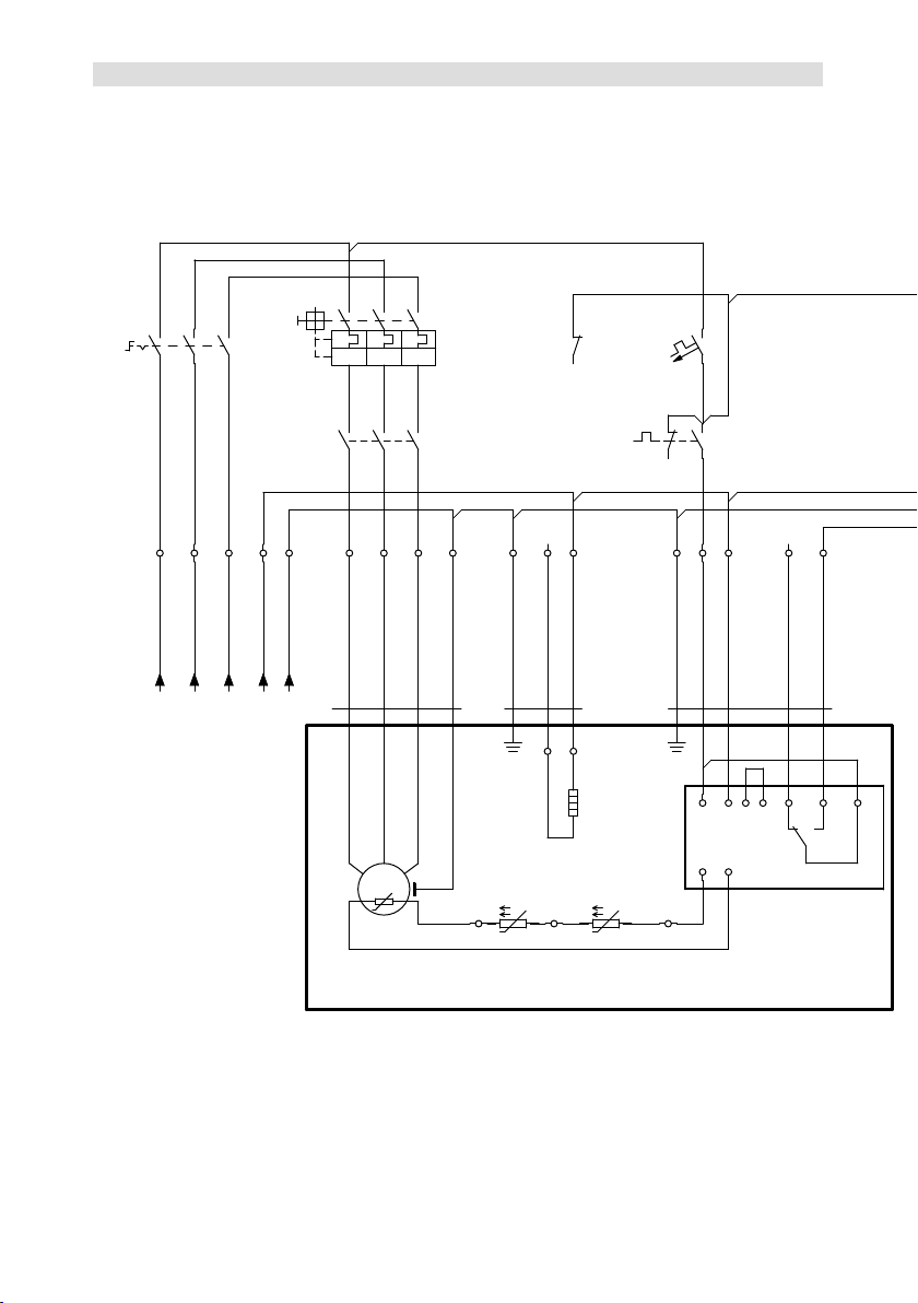
Weitere Anschlüsse siehe Maßzeichnung Verdichter
For further connections see dimensional drawing of the compressor
Maße in mm
Dimensions in mm Änderungen vorbehalten
Subject to change without notice
Luftgekühlter Verflüssigungssatz / Air-cooled condensing unit
Aggregat
Bezeichnung /
unit description
Bestehend aus / composed of:
Verdichter
Teile Nr. /
compressor
part-no.
X-Verdichter
Teile Nr. /
X-compressor
part-no.
Sammler
Teile Nr. /
receiver
part-no.
Inhalt
(Ltr.) /
volume
(Ltr.)
SHG(X)34e/215-4 PB 16050 16058
60028 8
SHG(X)34e/215-4 SPB 16054 16062
SHG(X)34e/255-4 PB 16051 16059
SHG(X)34e/255-4 SPB 16055 16063
SHG(X)34e/315-4 PB 16052 16060
SHG(X)34e/315-4 SPB 16056 16064 60029 10SHG(X)34e/380-4 PB 16053 16061
SHG(X)34e/380-4 SPB 16057 16065
Anschlüsse /
Connections
SHG34/215 (S)PB
SHG34/255 (S)PB
SHG34/315 PB
SHG34/315 SPB
SHG34/380 (S)PB
SV Saugabsperrventil, Rohr (L)* mm / Zoll 28 - 1 1/8" 35 - 1 3/8"
Suction line valve, tube (L)* mm / inch
FLA Flüssigkeitsaustritt, Rohr (L)* mm / Zoll 12 - 1/2" 16 - 5/8"
Liquid outlet, tube (L)* mm / inch
SI Anschluss Sicherheitsventil Zoll 1/2" NPTF
Connection safety valve inch
Y1 Anschluss Flüssigkeitsseite, absperrbar Zoll 7/16" UNF
Connection liquid side, lockable inch
Y2 Anschluss Flüssigkeitsseite, nicht absperrbar Zoll 7/16" UNF
Connection liquid side, not lockable inch
Y3 Anschluss Drehzahlregler Zoll 7/16" UNF
Connection Speed Controller inch
(L)* = Lötanschluß
(L)* = Brazing connection
1.1023-16145.2
Typ /
type Teile-Nr./
part-no. Typ /
type Teile-Nr./
part-no. Typ /
type Teile-Nr./
part-no. Typ /
type Teile-Nr./
part-no.
SHG34e/215-4 PB 16138 SHGX34e/215-4 PB 16146 SHG34e/215-4 SPB 16142 SHGX34e/215-4 SPB 16150
SHG34e/255-4 PB 16139 SHGX34e/255-4 PB 16147 SHG34e/255-4 SPB 16143 SHGX34e/255-4 SPB 16151
SHG34e/315-4 PB 16140 SHGX34e/315-4 PB 16148 SHG34e/315-4 SPB 16144 SHGX34e/315-4 SPB 16152
SHG34e/380-4 PB 16141 SHGX34e/380-4 PB 16149 SHG34e/380-4 SPB 16145 SHGX34e/380-4 SPB 16153
4x 8
649
Y2
Y1
X
Weitere Anschlüsse siehe Maßzeichnung Verdichter
For further connections see dimensional drawing of the compressor
Maße in mm
Dimensions in mm Änderungen vorbehalten
Subject to change without notice
Luftgekühlter Verflüssigungssatz / Air-cooled condensing unit
Aggregat
Bezeichnung /
unit description
Bestehend aus / composed of:
Verdichter
Teile-Nr. /
compressor
part-no.
X-Verdichter
Teile-Nr. /
X-compressor
part-no.
Sammler
Teile-Nr. /
receiver
part-no.
Inhalt (Ltr.) /
volume (ltr.)
SHG(X)34e/215-4 P&P 16050 16058
60028 8
SHG(X)34e/215-4 SP&P 16054 16062
SHG(X)34e/255-4 P&P 16051 16059
SHG(X)34e/255-4 SP&P 16055 16063
SHG(X)34e/315-4 P&P 16052 16060
SHG(X)34e/315-4 SP&P 16056 16064 60029 10SHG(X)34e/380-4 P&P 16053 16061
SHG(X)34e/380-4 SP&P 16057 16065
1.1023-16129.2
Typ /
type Teile-Nr./
part-no. Typ /
type Teile-Nr./
part-no. Typ /
type Teile-Nr./
part-no. Typ /
type Teile-Nr./
part-no.
SHG34e/215-4 P&P 16122 SHGX34e/215-4 P&P 16130 SHG34e/215-4 SP&P 16126 SHGX34e/215-4 SP&P 16134
SHG34e/255-4 P&P 16123 SHGX34e/255-4 P&P 16131 SHG34e/255-4 SP&P 16127 SHGX34e/255-4 SP&P 16135
SHG34e/315-4 P&P 16124 SHGX34e/315-4 P&P 16132 SHG34e/315-4 SP&P 16128 SHGX34e/315-4 SP&P 16136
SHG34e/380-4 P&P 16125 SHGX34e/380-4 P&P 16133 SHG34e/380-4 SP&P 16129 SHGX34e/380-4 SP&P 16137
Anschlüsse /
Connections
SHG34/215 (S)P&P
SHG34/255 (S)P&P
SHG34/315 P&P
SHG34/315 SP&P
SHG34/380 (S)P&P
SV Saugabsperrventil, Rohr (L)* mm / Zoll
mm / inch 28 - 1 1/8" 35 - 1 3/8"
Suction line valve, tube (L)*
DV Druckabsperrventil, Rohr (L)* mm / Zoll
mm / inch 16 – 5/8" 16 – 5/8"
Discharge line valve, tube (L)*
FLA Flüssigkeitsaustritt, Rohr (L)* mm / Zoll
mm / inch 12 - 1/2" 16 - 5/8"
Liquid outlet, tube (L)*
FLE Flüssigkeitseintritt, Rohr (L)* mm / Zoll
mm / inch 12 - 1/2" 16 – 5/8"
Liquid inlet, tube (L)*
SI Anschluss Sicherheitsventil Zoll / inch 1/2" NPTF
Connection safety valve
Y1 Anschluss Flüssigkeitsseite, absperrbar Zoll / inch 7/16" UNF
Connection liquid side, lockable
Y2 Anschluss Flüssigkeitsseite, nicht absperrbar Zoll / inch 7/16" UNF
Connection liquid side, not lockable
Y3 Anschluss Drehzahlregler Zoll / inch 7/16" UNF
Connection Speed Controller
(L)* = Lötanschluss
(L)* = Brazing connection
-
-
F
E
D
C
A
F
E
D
C
41
A
B
5
6
7
8
1
2
34
5
6
78
Zeichn.-Nr. / Drawing no. :
B
32
166951
Part-No. Maßstab /
±0.1
über / above
Freigabe / Approved
zy
Der Lieferant muss sicherstellen, dass die Ware
in einwandfreiem Zustand angeliefert wird
(Korrosionsschutz, Verpackung für sicheren
Layh
Allgemeintoleranzen / General tolerances
Drawing-No.
bis / up to
Dok-ID:
xw uts
-
Kunde / Customer:
packaging for safe transportation).
model or design.
-
in proper conditions (corrosion prevention,
DIN ISO 2768-mK
Ra Rz
18.05.16
Ersatz für / replacement for:
The supplier has to ensure the delivery of parts
Transport).
prohibited. Offenders will be held liable for the Dimension Passung / Clearance
Baumustergeprüft / Type examination:
--
K.-Auftrag / C.-Task:
Projektleiter / Project leader:
120
400
±0.5
0.5
6
GEA Bock GmbH - Benzstraße 7 - 72636 Frickenhausen - Germany - www.bock.de
-
-
-
Unbemaßte Radien / Undimensioned radii:
-
Bearb. / EditedDatum / Date
payment of damages. All rights reserved in the event Änd.-Nr. / Mod-No.
Werkstoff (Zeile 2+3 alternativ) /
Base part, Raw part:
-
-
Geprüft / Appr.
NameDatum / Date
18.05.16
Material (Line 2+3 alternative):
Ausgangsteil, Rohteil /
Workpiece edges
DIN ISO 13715
Erstellt / Drawn
Geprüft / Verified Zuder
Büttner
1/3
Oberflächenbehandlung, Härte / Treatment of surface, Hardness:
18.05.16
Werkstückkanten /
Page:
400 Benennung / Description:
±0.8
1000
306
-
±0.3
12030
-
Blatt /
±0.2
of the grant of a patent, utility /
DIN EN ISO 1302
Zust. / Rev.
Gußtoleranzen / General casting tolerances:
Gewicht / Weight: (kg)
Zeichnungs-Nr. /
Indication of surface texture
Scale:
%
U - SHG34e/380-4 SP&P
Rz 25
Rz 160
25 0,05 Rz 1,6
0,3
0,7
1,6
2Rz 16
6,3 Rz 63 Rz 6,3
Rz 12,5 Status:
-
-
in Bearbeitung (CAD)
Nein / No 16129 .2
A - SHG34e/380-4 SP&P
-
10231.
Weitergabe sowie Vervielfältigung dieses Dokuments,
Verwertung und Mitteilung seines Inhalts sind ver-
boten, soweit nicht ausdrücklich gestattet. Zuwider-
handlungen verpflichten zu Schadenersatz. Alle
Rechte für den Fall der Patent-, Gebrauchsmuster-
oder Geschmacksmustereintragung vorbehalten.
The reproduction, distribution and utilization of this
document as well as the communication of its
contents to others without express authorization is
Maß
Oberflächenangaben /
Teile-Nr. /
Layh
+2
968
+2
679
60-80