GEAppliances UK-kit-4 Specification sheet

Htoget
thebest from
use/kcare lpi!!
‘II-E’Problem!!?dver’ pi
Instihtion -p5
What’s inThisKit ptii
otherPartsYouNeed -jp7’
InsWWngtheWaterLine@7
GE AnswerCenter@
800.626.20W
hlsta Pkasek2!Je thisbookwith
UseandClueand
Instihtionof
UK-NT-4
UK-UT-5
Thesekits fit mostrmoqdsCamng
forUK-KIT-Im
IJK-’KI
Can be used in all “M” (1971)
and later GE and FIotpoint
~efrigeratorsexceptthose
with an ice dispenser.
UK-KIT-4 is designed for all
top-freezerno-frost refrigerators
17cu. ft. and larger and all
side-by-sidemodels except
those with an ice dispenser.
UK-KIT-5 can be used in all
14through 16cu. ft. top-freezer
no-frost refrigerators.
u’ youm.%replacingan
icenmker‘withUK-IK’
or 1.JK-mT-5.9seepage’ 5.
theconsumer.
—————-
—
————.—
—..
._____ —.—-_-——----
[

Useand Care
Imtructiom
Fix’Yoursafety
Donotplacefingersor hands
ontheaumnnaticicernakhag
mwhatism whiletherefrigerator
isplugged h. Thiswillhelp
protectyou frompossibleinjury.
Itwillalso preventinterference
withmovingpartsofthe ejector
mechanismand theheating
elementthatreleasesthe cubes.
Under certainrarecircumstances,
icecubesmay be disedored9
usuallyappearingwith a green-
bluishhue. The causeof this
unusualdiscolorationis apparently
acombinationoffactorxsuchas
certaincharacteristicsof local
waters,househoidplumbingand
theaccumulationofcopper saltsin
an inactivewatersupply line which
feedsthe icemaker.Continued
consumptionofsuch discolored ice
cubesmaybe injuriousto health. If
suchdiscolorationis observed,
discard the icecubesand contact
thedealer from whom the icemaker
or refrigerator waspurchased, a
FactoryService Center, or an
authorized Customer Care@
servicer.
SAVETHWE
INSTRUCTIONS
HowtheIcemakerWork
Waterfillsthe empty cube mold
(Fig. 1)when freezercompartment
has cooled to freezingtemperature.
Coldair isforceddirectlyovermold.
Storage Bin
Fig. 2
When frozen, the cubesare rotated
up and out ofthe mold (Fig. 2).
The sweeper arm ejects them into
the ice storagebin below.
The feelerarm (Fig. 3) senses
when bin is fill and signals
icemakerto stopejectingmore
cubes. However,themold hasbeen
refilledandcubes frozen sothe
new supplyis ready when needed.
As soonas ice is removedfrom the
bin, the feeler arm signalsthat
more isneeded. Icemaker resumes
operationbyejecting ready-and-
waitingfrozen cubes.
2

I
Will Operate
LTostartIcemaker, lowerthe
feelerarm to the ON position.
Makesure the icebin isatthe
rear ofthe freezer compartment,
belowthe icemaker.
2. When Icemaker is first
connectedor after anyextended
period ofnon-use, yo~should
discard the first fewbatchesof
cubes. Use ice regularly to
maintainthe best quality.
3. The feeler arm mustbe free to
operateupwardandoutwardover
thetopoftheicestoragebinduring
eachice-deliverycycle.Makesure
packagesinthefreezercompartment
donotinterferewithitsmovement.
4. Raise the feeler arm to theOFF
(up)positionwhen:
a. Icestoragebinistoberen-wed
forextendedperiodoftime.
b. Refrigeratorisnotto beusedfor
aconsiderabletime,suchas
vacations.Also,turnoffthewater
supplytotheIcemakerinthis
instance.
c. W:~tersupplyistobeshutofffor
scvcraihours.
6.TheIcemakerejectscubesin
groupsanditisnormalforseveral
cubestobejoinedtogether.
7.Icecubesthathavebeeninthe
icestoragebinforaconsiderable
lengthoftimemaypickupoff-flavor
tastes,sticktogether,andgradually
becomesmaller.Wesuggestthat
thesecubesbethrownaway.
8.Youmay,onoccasion,findafew
smallerthannormalcubesinthe
bin.Thisisprobablycausedbylow
waterpressureattimeofwaterfill.
9.Theicestoragebinshouldbe
cleanedoccasionallyinwarm
water.Rinseandwipedry.Be
suretoshuttheIcemakerOFF
whencleaningthebin.
10.Keepiceleveltokeepitcoming.
Ifcubesshouldbuildupinonearea
oftheicestoragebinafterbeing
ejectedfromthemold,just level
themoutwithyourhand.Keep
cubesdistributedevenlyandthe
bincanreachitsmaximumcube
capacity.
5, DL1ringoperation,youmayhear
certainsounds,suchas thehumof
[hemotor,movementofthecube
g=##!cjcctor,hummingor clickingofthe
\$&=3~}l~terv:~lve,andr:~ttlingoficcas it
fallsintothebin.Thesesoundsare
normal.
3

savetimeandmoney.*•
kfom yummqud service,d’mckthe following:
IPROBLEM
WATEROVERFLOWS
ICE MOLD
I(X CUBESEL4VE
ICNX?R/TASTE
‘mssmLE CAUSE AND REm/DY
@Fe&x Arm up in “OIF’ position-shcwk! bedownin “ON” position.
*~~&ma&n@g~fiingne~e~~ary~q@y ofwater+Make sure $va@K
SUppiy kconnected
and turnedon.
*~r=r compa~ment too ~~m+ ~rn temperaturecontroltocolder setting.
(Se&yourrefrigfmtoruseandcarebook.)
*~~befjtoos~~~- ~~~t.~ff v~~v~connectingrefrigeratortohomewaterhlf3Illfiybe
dogged. unclog it.
~ ~se iceqydady. Discardold cubes.IceShred forextendedperiOdSWilld3SOrb
odorswhich.affwttaste.
sIcesto~e bin needs to beemptiedandwashed. ,,
@Urmeak3dpackagesin refrigeratorand/or freezer compartments maybe transmitting
odorhaste toice cubes.
@Interior of refrigeratorneedsc!eaning—seeyour refrigerator,’useand careboqk.
If you need !mOme Mp...cd, tdl free:
GEhswer fceKm!r@-
8W.626.20W
consumer information service
EYOUNeedservice
Toobtainservice,seeyour
warrantycmthebackpageof
thisbook.
We’reproudofourserviceand
wantyouto bepleased.If forsome
reasonyouarenothappywiththe
serviceyoureceive,herearethree
stepstofoIlowforfurtherhelp.
FIRST,contactthepeoplewho I?HNALJX,ifyourproblemisstill
servicedyourappliance.Explain notresolved,write:
whyyouarenotpleased.In most MajorAppliance
cases,thiswillsoivetheproblem. ConsumerActionPanel
NEXT,ifyouarestillnotpleased, 20NorthWackerDrive
writeallthedetails-including Chicago,Illinois60606
yourphonenumber—to:
Manager,ConsumerRelations
GEAppliances
AppliancePark
Louisville,Kentucky40225
I
-!

-0Instructions
it’s importantthat youusethe
water valveandWtube
extension thatcomewith this kit
eventhough yourrefrigeratormay
alreadyhavethem installed.
Theold vahmwillnotallowenough
waterthrough to fill the icemaker
properlyand can causedamage.
Thefilltube extension needsto
beadifferent length than the
original tube for properwaterflow.
Cut the tube tothe length indicated
for your modelof refrigerator.
Rages 8“16containsix
ditierent installation
hstmcths.
The actual installationofthe
icemakerwill dependon which
modelrefrigeratoryou have.There
isalabelon the backof the
refrigeratorthat will tell you
whetherto useInstructionA, B,C,
D,Eor E
5

@
@
SlottedHex-HeadScrew
HoseClamp
@
Adhesive-BackedFasteners
DateInstalled
ha18r
WarrantyLabel
._ —.. ..—
(9)
w
WaterLine Clamp
IIceBucket
L
@
WaterLine Clamp
(usedonly with
Instruction Sheet F)
@
6

PAms MT
1. WaterValveAssembly
2. Siotted Hex-HeadScrew
3. HoseClamp
4. Adhesive-BackedFasteners
5. Fill TubeExtension
6. Icernaker
7. Ice Bucket
8. WarrantyLabel
9. WaterLineClamp
10. WaterLineClamp
11. User Instruction and Warranty
LK%EW!THlNsTRumioN SHEET
xIxIxIxIxlx
xIxIxIxIxINo
xIxIxIxI%(
AIx
xxxx
-+-
xx
xxxxxx
xIxIxIxlx Ix
xIxIxIxIxIx
xIxIxIxIxIx
xIxIxIxIxINO
Ix
xIxIxIxIxIx
OTHERPARTSYOU NEED. . .
Copper tubing, shut-offvalve and fittings necessary UK-KIT-5also contains abucketsupport for useas
to supply water to your refrigerator are not included described in Instruction A.
in UK-KIT4 or UK-KIT5.
Youcan purchase acomplete water supply kit from
your GEor Hotpoint dealer.
Recommended watersupply kits are Cat. No.
WX8X2(15feet of copper tubing), WX8X3(20feet),
or WX8X4(25feet). For Instruction Bonly.. you will need a higher
bucketsupport and different fill tube extension.
Seepage 12.
7

Preparingthe
backofthe
cabinet
FkMd each stepthoroughly
before proceeding.
Took needed:
sPhillips-type screwdriver
~Blade-type screwdriver
~Sharp knife
~Pliers
step1
cation:
Atbo~omof rearof refrigerato~
remove2screwsholding
compressorcompartmentcover
(if covered)andsavethemfor
reinstallationlaterBendcoverback
for accessto thecompartment.
s&p 3
~Locatefemaleconnectorplug
(A)whichisattachedto cabinet
byawiretie. Removewiretie
anddiscardit.
C+Removeanddiscardtapefrom
femaleconnectorandplugonto
maleterminalsonwatervalve
(1).Eitherwirecangoon either
terminal.
(c) Fastenwatervalveto cabinet
edgehole(X) usingslotted hex-
headscrewU) from kit. DONOT
DRILLANYADDITIONALtiOLEs.I
step4
~Pushmetalclamp(g)ontolower
flangeofcabinetbackdirectlyin
linewithwatervalveasshown.
Checkplasticwaterlinenuton
bottomofwatervalvetobesureit
ishandtight.DONOFUSETOOLS.
IBRe-installcompressor
compartmentcoversoplastic
waterlineisdirectedoutof
compartmentandupbackof
refrigeratorFittingonwatervalve
shouldextendthroughholein
coverasshown.
Note:Onsomemodels,youmay
haveto usescissorsto cutthe
compressorcompartmentcover
just enoughto allowthewater
valveinletto stick outsothe
copperwaterlinecanbe
connectedto it late~
step5
Onmodelsthat havecondenser
tubing onbackofcabinet,insert
the pkstic waterline between
tubingandbackof cabinet.
s@p6
0Removesmallplasticcap(B)
from bottomoffill tubeinlet
locatedinupperrightrearcorner
cf refrigerator.Squeezeendsof
hoseclamp(3)from kitwith
pliersandslideclampoverfill
tubeinlet.Whilestill squeezing
clamp,insertplasticwaterline
intoinletasfarasit will go
(approximately1“). Thenslide
clampdownwardto capture
plasticwaterlineinplace.
@Makesurefill tubeinletis
aimeddownasshownbelow.
I
step7
Fasten~lasticwaterlineto bac
ofcabinetwith adhesive-backed
fasteners(4), spacingfasteners
asshownto takeupslackinline.
0s~.
&~~
&
L_ Adhesive-backedfasteners
for nlastic water line
II
——____----
I—77- 1I
=Adfmsive-backfxffastenels
forplasticwaterline I
8(continued on page 70)

Preparingthe
backfofthe
cabinet
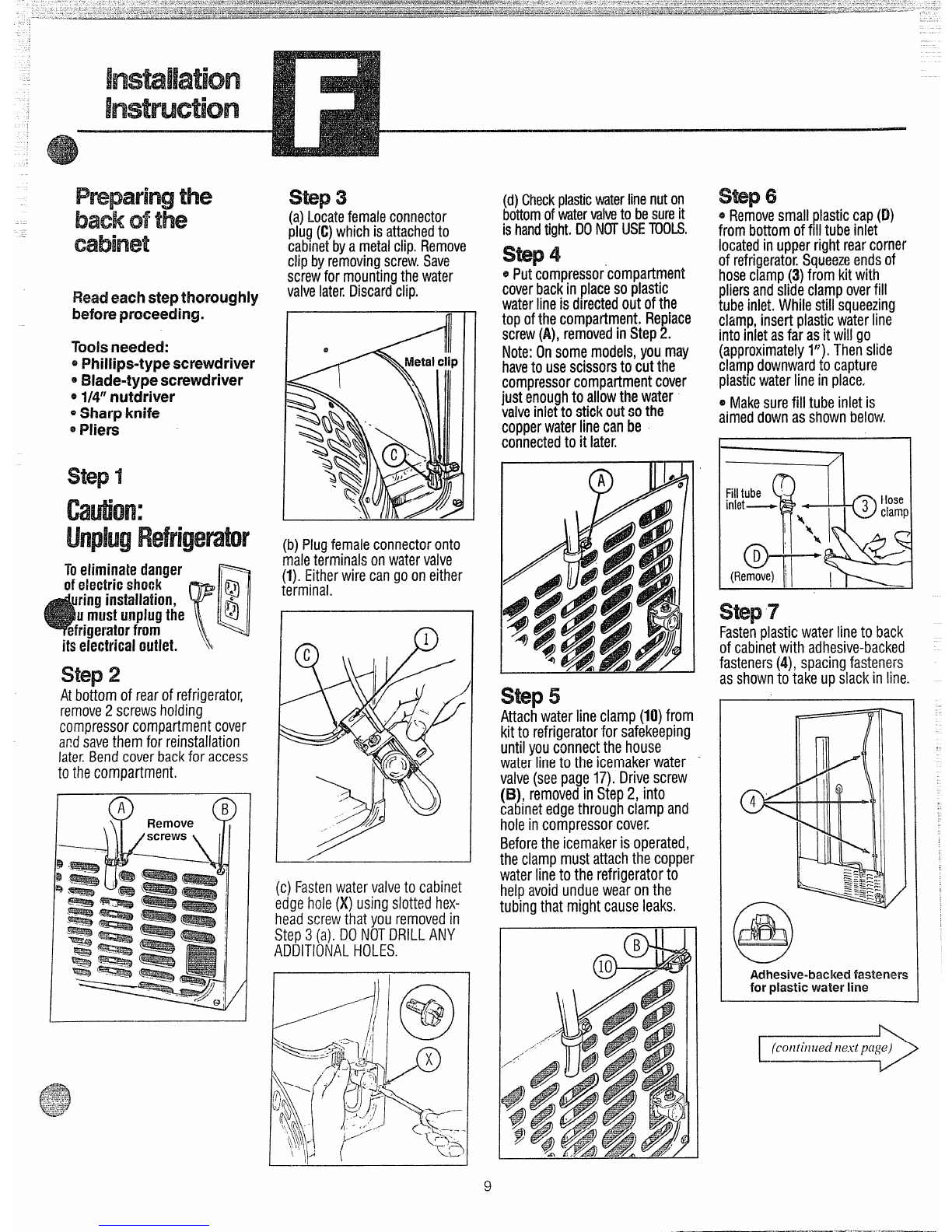
Read each stepthoroughly
beforeproceeding.
Took needed:
~Philiips-typescrewdriver
*Blade-typescrewdriver
*~/4°nutdriver
~Sharp knife
@Pliers
cation:
of electric SIMM
its electrical outlet. “
step2
At bottomof rearof refrigerator,
remove2screwsholding
compressorcompartmentcover
andsavethemfor reinstallation
late~Bend cover back for access
tothecompartment.
step3
(a)Locatefemaleconnector
plug(C)whichisattachedto
cabinetbyametalclip.Remove
clipbyremovingscrew.Save
screwfor mountingthewater
valvelate~Discardclip.
(b)Plugfemaleconnectoronto
maleterminalsonwatervalve
(l).Eitherwirecangoon either
terminal.
I
(c) Fastenwater valve to cabinet
edgehole(X)usingslott~dhex-
head screw that you removed in
Step3(a).DONOTDRILLANY
ADDITIONALHOLES.
,
(d)Checkplasticwaterlinenuton
bottomofwatervalveto besureit
ishandtight.DONOTUSETOOLS.
s~p 4
~Putcompressor’compartment
coverbackinplacesoplastic
waterlineisdirectedoutofthe
tonofthecom~artment.Re~lace
sc’rew(A),rembvedinStep2.
Note:I% somemodels,youmay
haveto usescissorsto cut the
compressorcompartmentcover
just enoughto allowthewater
valveinletto stick outsothe
copperwaterlinecanbe
connectedto it later.
o
A
step5
Attachwaterlineclamp(10)from
kitto refrigeratorfor safekeeping
untilyouconnectthe house
waterlineto theicemakerwater
valve(seepage17).Drivescrew
(B), removedinStep2, into
cabinetedgethroughclampand
holeincompressorcover
Beforethe icemakerisoperated,
theclampmustattachthecopper
waterlinetothe refrigeratorto
helpavoidunduewearonthe
tubingthat mightcauseleaks.
.. .
Swp6
~Removesmallplasticcap(D)
frombottomoffill tubeinlet
locatedinupperrightrearcorner
ofrefrigerator.Squeezeendsof
hoseclamp(3)from kit with
pliersandslideclampoverfill
tubeinlet.Whilestill squeezing
clamp,insertplasticwaterline
intoinletasfar asit will go
(approximatelyV). Thenslide
clampdownwardto capture
plastlcwaterline inplace.
~Makesurefill tubeinletis
aimeddownasshownbelow. I
step7
Fastefiplasticwaterline to back
ofcabinetwith adhesive-backed
fasteners(4), spacingfasteners
asshownto takeupslackinline.
Adhesive-backed fastemers
for plastic water line
(continued next p(ige)
9
.—-...-—...—-.——

.—.
-. Remove and discard existingiceservice.
Follow inst-~uctions in appqxiak Step 8A belovv.
.step8A step8A step8A step8A
Removeicetraytunnel.
oDisengageicetunnelsideandbot-
tomfromretaininghooks.Lowertun-
neluntilside is clearoffreezershelf
and removeit from freezer.Discard
icetunnel.
Removeicetraytunnel.
oRemovetwo screws(C) andsave
themfor installationof icemaker.
oLift icetraytunneloff plastichook
(D)anddiscardit,
/1
Removeicetraytunnel.
oAsYoulift tabonleft sideintunnel
-..w’-
//
‘4--
d---.-_:-_.,+-
,---
-1 --s--
/
steptvi
Discardshe~.
J!! I
Removeice tray shelf.
oLift ice tray shelf upto disengage
from tabs oncabinetwall andpull it
forwardas shown.
RepositionfreezerShelfm
with bladeof screwdriver,pull tunnel
forwardandout.Discardicetunnel.
oTilt icetrayshelfandremoveit.
Discardshelf.
RemoveIcetray shelf.
oPull icetrayshelfto disengage
pinsfromholesoncabinetwfiil.
Follow instructions in appropriate Step 8B below.
step8!3 stepml step8B
Applicableto modelswith apartial- Applicableto modelswithafull-width Applicableto MOMS with apartial-
width shelf suspendedfrom freezer shelf andalternateshelf locations. widthshelf restingonfreezerfloor.
top, or tomodelswith asteppedfull- “Repositionsheif at iowestievel. oReiocateshelfagainstleftwaii(under
width shelf. icemakermountingarea).
oRemoveshelftoprovideworkingroom
duringicemakerkit installation,
ITore~ositionthe2-pieceshelf
Sllppirts
Slidepart(E)upoff base

Installation
Instruction !nsidefreezerCompatiment
step9
Removescrew(A) that holdselectri-
calplugcoverinplace.Discardscrew
andcover,
step10
*Removeplasticinsert(B)fromair
ductanddiscardit.
~Loosen two icemaker mounting
screws (C) approximately1/2”. 00
NoT13EMovESCREWS.-
step11
Cutthefill tubeextension(5)to then
length with asharp knife or single-
edaerazorbladeandslideit onthefill
tu~eagainstthestop.
, ,,
.——
step12
Place icemakerin freezercompart-
mentasshown.Inserticemakerpower
cordplug(D)intosocketonsidewall,
makingsureprongsare matchedto
correspondingholesandplugisfirmly
$wtod insw-ket. - - -
step13
@Lift icemakerandpositionrearopen-
ing in fill cup (E) overfill tube ex-
tension (5). Hangicemaker on two
screws(C)S
Makesure:
~electrical plug is still firmly in
socket.
ofill tubeextension(5) is still in fill
cup opening–check rearof refriger-
ator to makesure fill tube has not
beenpushedout of the backof the
refrigerator.
eicemakermountingscrewsare lo-
catedinuppermostpositionofmount-
ingslots.
THENTIGHTENICEMAKERMOUNT-
INGSCREWSSECURELY
step1’4
Theicemakershouldfeelsecurewhen
youlift theicemakerfeelerarm(F)to
the“OFF”(up)position.Leaveitthere
until the refrigeratoris connectedto
!hewatersupplyto preventpremature
operation.
I‘c)icemaker
Fwillopwate
stepw
Replacefreezershelf. Movebucket
supportandicebtiuket(7)intoplace
directly under the icemake~See
illustrationbelow,
NOTE:Checkagaintomakeswe (ha
icemakerpow$rcordplugIsfully in-
wtod lmtoMsocketwith prongs
matchedtocorrespondingholes.
Checkagairrto makewre the ice-
makerfeelerarm(F)is intir$“OFF”
(up)position,
S&p 16
Aiabel(8)isprovidedinthekittorecord
the dateof installationfor warranty
purposes.Applyit to thebackofthe
refrigerator,
SWp1-7
‘TIMwarrantykwthe hxmaker isprintedontheIbackpageIMhis bookie!.Keep
this bookl~tWWIymrIFkfrigmtmilh 8CareINMIk.
Theicemakerinstallationisnowcomplete.Refertowaterlinehook-upinstructions
onthebackoftherefrigeratorforconnectiontohomewatersupply.Afterwaterline
installationis completed,lowericemakerfeelerarmtothe“ON” (down)position.
Theicemakingo@? $vil!Wbeginuntil theicemakerandfreezercompafl~fiefil
reachoperatingtemperature,thenicemakingwi!l beginautomatica~!~
—
/
—
\5uck@ support
(SIOIXAml is
tothefrcmt)
11
.-.—.—.—,..- ,.---,.-.-—...,
-.......

MODELSTNATCALLHIR THIS
fNWRU~!ON SHEETNEEDA
HIGHERBUCKETSUPPORTAND
D!FFERENTFILLTUBETHANIS
PROVIDEDNJTHISWT.THE
HIGHERtWFWRT CANONLY
BEtBW.11ONMODELSWITH
INWRUUION B.
Obtainthisnewsuppmtandafilltube
extensionatnochargebyrequesting
Pub.No.2-1003from General
Electric Publications, c/o Dri-View
Manufacturing Co., 4706 Allmond
Ave.,Louisville,KY40209.
step 9
0Removescrew(A)thatholdselectri-
calplugcoverinplace.Discardscrew
arrdcover,
*Loosen two screws (C) approxi-
mately1/2”. DONOTREMOVETHE
SCREWS.
I8
I!l+---. I
step%0
Takethefill tubeextension(5)fromthe
supplementarykit 2-1003thatyougot
bymail andslide it ontothe fill tube
againstthe Stopr
I?T‘1r
-
0.-
“1111
/
5,
+/;
+!!!z?J 1
~iqj ~1
I’iace icemaker in freezer cornpart-
nwit asshown.Inserticernakerpower
~il[d pl[]g(D)intosocketOrIsids wall,
~l~;fingsure prongs we matchedto
~[l[respor]dingholesandplugis firmly
s;~Jted irt socket, When inserted,
power cord plug shouki fit flush to
htwcr wall.
Insidefreezercompartment
step12
●Lifticemakerandpositionrearopen-
ingin fill cup (E)overfill tubeexten-
sion(5).Hangicemakerontwoscrews
(c).
Makesure:
●electrical plug is still firmly in
socket.
.fill tubeextension(5) is still in fill
cupopening–check rearof refriger-
ator to makesure fill tube has not
beenpushedout of the backof the
refrigerator. .
‘icemakermountingscrews are lo-
catedinuppermostpositionofmount-
ingslots.
THENTIGHTENICEMAKERMOUNT-
INGSCREWSSECURELY
‘o icemaker
Fwillof)erate
step14
Replacefreezershelf. Movebucket
suppoflandicebucket(7)intoplace
directly under the icemaker. See
illustrationbelow.
NOTE:Checkagainto makesurethe
icemakerpowercordplugis fully in-
serted into its socket with prongs
matchedto cormpondingholes;
Check againto makesure the ice-
makerfeelerarm(F) is inthe“OFF”
(up)position.
I
I
stf?p1!5
Alabel(8)isprovidedinthekittorecord
the dateof installation for warranty
purposes.Applyit to thebackofthe
refrigerator.
step!6
The warrantyfor the icwnak$ris
printedonthehackpageofthisbook-
iet. Keep this booklet with your
Refrigeratorthe &Carehook.
Theicemakerinstallationisnowcom-
plete. Refer to water line hook-up
instructionsonthebackoftherefrig-
eratorfor connectionto homewater
supply.Afterwaterlineinstallationis
completed,lowericemakerfeelerarm
tothe“ON” (down)position.
Icemakiflgcycle wil\ not begirruntil
icemakerandfreezer compartment
reach operating temperature, then
icemakingwill beginautomatica~l~
III iII Ill //
Il\- 11 1! Ill /+–—---- --
Theicemakershouldfeelsecurewhen
youlift the icemakerfeelerarm(F)to
the“OFF” (up)position.Leaveitthere
until the refrigeratoris connectedto
[hewatersupplytopreventprema[ure
operation.
12

Installation
Instruction Insidefreezercompartment
step9
●Removescrew(A)that holdselec-
trical plug cover in place. Discard
screwandcover.
*Removelight shield insert (B) and
djscardit,
oLoosentwo screws (C) approxi-
mately1/2’! DONOTREMOVETHESE
SCREWS.
$
step10
Cutthefill tubeextension(5)to them
lengthwith asharpknife or single-
edgerazorbladeandslideit ontothe
fill tubeagainstthestop.
,7
step11
Place icemakerin freezercompart-
mentasshown,Inserticemakerpower
cordplug(D)intosocketonsidewall,
makingsure prongsare matchedto
correspondhgholesandplugisfirmly
seatedinsocket.
step 12
~Lift icemakerandpositionrearopen-
ing in fill cup (E) overfill tube ex-
tension (5). Hangicemakeron two
screws(C).
Makesure:
oelectricalplug is still firmly in
socket.
ofill tubeextension(5) is still in fill
cup opening–check rearof refriger-
ator to makesure fill tube hasnot
beenpushedout of the backof the
refrigerator.
oicemakermountingscrewsare lo-
catedinuppermostpositionofmount-
ingslots.
step13
Theicemakershouldfeelsecurewhen
youlift theicemakerfeelerarm(F)to
the“OFF”(up)position.Leaveitthere
until the refrigeratoris connectedto
thewatersupplyto preventpremature
operation.
oicemaker
Fwilloperate
step 14
Putice bucket(7) into placedirectly
undericemaker(totheleftandallthe
way to the rear of the shelf under
icemaker).
NOTE:Checkagainto makesurethe
icemakerpowercordplugis fully in-
serted into its socket with prongs
matchedto correspondingholes.
Checkagainto makesure icemaker
feelerarm(F)isin“OFF”(up)position.
THENTIGHTENICEMAKERMOUNT-
INGSCREWSSECURELY \Ml
,~1
J_
/1
GzEl -
——........ ——___
step%5
Alabel(8)isprovidedinthekittorecord.
the dateof installationfor warranty
purposes.Applyit to thebackof the
refrigerator,
step 16
Th? wwrantyforhicemaker is
printedonthehackpageofthisbook-
let. K%?pthis booklet with your
I%efrigwatorthe&Care book.
Theicemakerinstallationis nowcom-
plete, Refer to water line hook-up
instructionsonthebackofthe refrig-
eratorfor connectionto homewater
supply,After waterlineinstallationis
completed,lowericemakerfeelerarm
tothe“ON” (down)position.
Icemakingcycle will not beg~nwWl
icemakerand freezer con?part??mrft
reach operating temperature, then
icemakingwill beginautomatically
O
-F
Q7Icebucket
L-- /I
13
———...—_____________

IIII
I1
.
5
(in
s
aI

step9
Removeand discard electric plug
coverandmountingscrew(A).
step12
Removeanddiscardwhite plugfrom
upperleft corneroffreezerwall.
@m
--+
—
@_,
=&(.
e
Oeo
dCover
Aremoved
step10
Ifgrille(B)isnotinpiacesoitslouvers
directairtotheleft,turnitasfollows:
~Removescrew (Bl) which holds
grille(E).
I I
eRemovegrille (B), rotate it 90°
counterclockwise,and reinstall it as
shownbelow.
~Replacescrewandtighten.
step11
Loosenscrews (C)hut donot screw
them all the wayout. Screwsshould
extendapproximately1/2” out from
freezclwall.
IBCutthefill tubeextension(5)tothe
ESHORT lengthifyour refrigerator
is22.0or22.5cubicfeet(usea
sharpknifeorsingle-edgerazor
blade.)Otherwiseusethe~long
length.Slidetheextensiononto
thefill tubeagainstthestop.
step13
Place icemaker on shelf in freezer
compartment as shown. Insert ice-
makerpowercordplug(D)intosocket
onside wall, makingsureprongsare
matchedto correspondingholesand
plugisfirnilyseatedinsocket.
.= “’iii’”
wA‘-----l
WI
C@)
‘+@
((l-I
step 14
*Lift icemaker and position rear
openingin fill cup (E) overfill tube
extension(5).Hangicemakerontwo
screws(C).
Makesure:
oelectrical plug is still firmly in
socket.
ofill tubeextension(5) is still in fill
cupopening–checkrearof refriger-
ator to makesure fill tube hasnot
beenpushedout of the backof the
refrigerator.
●icemakermountingscrewsare lo-
catedinuppermostpositionofmount-
ingslots,
THENTIGHTENICEMAKERMOUNT-
INGSCREWSSECURELY
step15
Theicemakershouldfeelsecurewhen
youlift theicemakerfeelerarm(F)to
the“OFF”(up)position.Leaveitthere
until the refrigeratoris connectedto
thewatersupplyto preventpremature
operation.
‘o
Ficernaker
willoperate
step16
Moveicebucket(7)intoplaceonshelf
directlyundericemaker.
NOTE:Checkagainto makesurethe
icemakerpowercordplugis fully in-
serted into its socket with prongs
matchedtocorrespondingholes,
Checkagainto makesureicemaker
feelerarm(F)isin“OFF”(up)position.
step17’
Alabel($)isprovidedinthekittorecord
the dateof installationfor warranty
purposes.Applyit to thebackof the
refrigerator.
step 18
The warranty for the icemaker is
printedonthebackpageofthisbook-
let. Keep this booklet with your
RefrigeratorUse&Carebook.
Theicemakerinstallationisnowcom-
plete. Refer to water line hook-up
instructionsonthe backofthe refrig-
eratorfor connectionto homewater
supply.After waterline installation is
completed,lowericemakerfeelerarm
tothe “ON” (down)position.
Icemakifigcycle will IW beginWi!
icemaker afld freezer compartment
reach operating temperature, [hen
icemakingwi// beginautomatically.

I
l?ern&eelectricplugcoverby
inserting standard screwdriver
Madein slot at bottom of cover
andapplying pressure upwards
whilepryingcoverawayfrom
freezerwall.Discardcover
Iremoved
step-m
Loosenscrews(E)butdonot
screwthemallthewayout.
Screwsshouldextend
approximately1/2” outfrom
freezerwall.
step11
(a)Removeanddiscardwhite
plugfrom upperleftcornerof
freezerwall.
(b)Cutthefill tubeextension(5)
to the“F” length.(Useasharp
knifeorsingle-edgerazorblade.)
Step13
*Lifticemaker and position rear
opening infill cup(G)overfill
tubeextension(5).Hang
icemakerontwoscrews(E),
Makesure:
~electrical plugisstill firmly h
socket.
@fill tubeextension(5)isstill in
fill cupopening–checkrearof
refrigeratorto makesurefill tube
has not beenpushed out of the
back of the refrigerator
@icemaker mounting screws are
located inuppermostpositionof
mountingslots.
THENTIGHTENICEMAKER
MOUNTINGSCREWSSECURELY.
step%?
Removeicemakerpowercord
from clip. Holdicemakerin
freezercompartmentasshown.
Inserticemakerpowercordplug
(F)intosocketonrearwall,
makingsureprongsarematched
to correspondingholesandplug
is firmlyseatedinsockeL
step%4
Theicemakershouldfeelsecure
whenyoulift theicemakerfeeler
arm(H)to the“OFF”(up)
position.Leaveit thereuntilthe
refrigeratorisconnectedto the
watersupplyto prevent
prematureoperation.
oicemaker
Hwilloperate
step15
Positionfreezershelfforicemaking
andmoveicebucket(7)into
placeonsheifundericemake~
Straighttwo-positionshelf
shouldbeinlower position. Step
shelf’s lower step should be
under icemaker Cantilever
shelf’s top lugs should be in tlh
slots upfrom bottomoftrack.
NOTE:Checkagainto make sure
the ihxmakerpowercordis
My insertedintoitssocket
withprongsmatchedto
correspondingholes.
Checkagainto makesure
icemakerfeelerarm(H)isin
“OFF”(up)position.
I
step16
Alabel(8)is providedinthe kit
to recordthedateofinstallation
for warrantypurposes.Applyit
to thebackofthe refrigerator.
step17
Thetiarrantyfortheicemaker
isprintedmthebackpageof
this booklet. Keepthis boolflet
with yourRefrigerator I!Jse
&care Book.
Theicemakerinstallationis now
complete.Referto waterline
hookupinstructions onthe back
oftherefrigeratorfor connection
to homewatersupply.After
waterlineinstallationis
completed,lowericemakerfeeler
armto the “ON” (down)position.
Icema!{iflg G$%!.$?wili L@b+q5
L!ntilicemaker andfkm%?%?(+r:
Compatimenfn%w?flopf%’afi’~j
temp@rat@re,iflfnl?nicema!fing
will begin 8@tDmafjca\lg
16

WaterLine
nshllationInstruction
Hyou use your refrigerator befcwe
connecting the water he, make sure the
item.aker feeler arm is kept in the’‘IOFF’92
position.
CAUTION:
~When using any electricaldevice(suchas a
power drill)during installation,be sure the device
isinsulated or wired inamanner toprevent the
hazard ofelectric shock.
@AHinstallationsmust be inaccordancewith
localplumbing coderequirements.
This water line installation is not wamantd
by the refrigerator micemaker mandadwm-r.
Follow these hstmdkms carddly to
mhhnize the risk of expensive water
damage.
WHATYouWILLNEEB
Acold water supply isrequired for
automatic icemaker operation. Water
pressure must bebetween 20and 120p.s.i.
Copper tubing, 1/4” (HI., shouldbe used to
connectthe refrigerator to the water supply.Do
not use plastic tubing fmplastic fittings
because the connectionbetween the water supply
and the refrigerator water valveinlet isunder
constantwater pressure. Also,certain types of
plastic tubing maybecomebrittle with age and
crack, resulting inwater leakage.
Ashutoff valve shouldbe connectedtothe cold
water line.The shutoffvalveshouldhaveawater
inlet with arnininmnn inside diameter d
5/32” at the pointofconnectionto the COLD
WATERLINE. Asaddle type shutoffvalve
permitted by manylocalplumbingcodesis shown
below.
Min. 5/32” dia. opening
Check your localplumbing codesbefore choosing
this type ofvalve.Werecommend using the
saddle valvesuppliedwith GE Water Supply Kits
WX8X2, WX8X3 and WX8X4.
17

1?
7
\wCompression
nut and
ferrule
Hole for
tubing
1%’WW42AIL PLuMBflNG HNSTALLAT80N
Refrigerator
connection
❑iHsFaLLs~um~~VAkVEOMNEAM$T
=UEN?LY USEB0MNMH6
waFERUHE.
a. Choosealocationfor the valvethat is easily
accessible.It is best to connect intothe side ofa
verticalwater pipe. When it is necessary to
connect intoahorizontalwater pipe, make the
connectionto the top or side, rather than at the
bottom, to avoiddrawing offany sediment from
the water pipe.
b. Drilla1/4” hole in the water pipe, using a
sharp bit. Removeany burrs resulting from
drilling the hole in the pipe.
c. Tighten the clamp screws until the sealing
washer begins to swell. G
❑RourE COWERTUB!HGBEWWEEMCokowkvER
EMLEa~o~~~~!~~wm~e
Route the tubing through ahole drilled in the
floor (behind the refrigerator or adjacent base
cabinet) as close to the wallas possible. Be sure
there is sufficient extra tubing (about 8feet coiled
into 3turns ofabout 10inches diameter) to allow
the refrigerator to moveout from the wallafter
instalh+tion.
Place the compressionnut and ferrule ontothe
end ofthe tubing and connectto the shutoffvalve.
JMakesure the tubing is fullyinserted intothe
valve.‘1’ightenthe compressionnut securely.
Before making Connection tothe
refrigerate, be sure Arigerahr pOwer
mrd is m~ plugged hto the vvall cmtlet.
a. Turn water on and flush out the tubing, making
certain that allforeign matter is removed from the
line.
b. Shut the water offafter about one quart of
water has been flushed through the tubing.
NUI’E: Some localitiesmay have sand or other
foreign matter present in the water supply in such
quantities thatthey may,in time, collectin the
screen ofthe water valveattached to the back of
the refrigerator and tend to reduce the water flow
to the icemaker. Where such conditions exist, we
recommend that an additional filter or strainer be
installed in the line near the refrigerator. If a
screen type strainer is used, it should be 80 mesh
or finer.
c. Cut offthe flared end ofthe copper tubing and
remove the flare nut from the tubing.
&Removethe plastic cap from the water valve
and plastic tube assembly. {a
U
-:‘:,,-

--- .-. -.., .—
)e. Connect copper tubingto the refrigerator
water valvebyplacinga1/4”compressionnut
and ferrule ontothe end ofthe tubingas shown.
f. Insert the end ofthe coppertubing intothe
water valveinletas far as possible.Whileholding
the tubing,tighten the fitting.
g. Fasten the coppertubingintothe clamp
providedto holdit in averticalposition.
❑7uRNOHWAFERANDCHECK
AuJ@BMr$FORLEAKS.
Tighten fittings if required tostop leaks. 1
IzlSm’THEucmKEa fEEkERAm
mVHEON [Bowfl) POSBWROM*
‘I’heicemakerwillnot begin tooperate untilit
reaches its operating temperature of 15°F.or
below.It willthen begin operationautomatically
ifthe icemaker is inthe ONposition.
EMOVE aHEREFR!GEM?ORMCKm?MEwAkL.
Arrange the coilofcopper tubing so that it does
not vibrate against the back ofthe refrigerator or
against the wall.
NmE$
The first few batches ofcubes should be thrown
away,so that remaining impurities in the water
linewillbe flushed out.
—
19

I——.
YOURAUTOMATIClCEMAKER
WARRANTY ~
Save proof of original purchase date such as your sales slip or cancelled check to establish warranty period, 4
—-——. _—.—.—.—--—
—-—,—-—...——..——
-—— .. . .. . ..— ————— ~~
_———..—.........
1WHATIs COVERED FULL CmK-$wm WARRANTY
f% oneyearfromdate of original
purchase, we will provide, freeof
charge,partsandservicelabor
in yourhometo repairor replace
anypart of the autonwtic
h?f??akerthat fails be~allsecda
manufacturingdefect.
This warranty is extended to
the original purchaser and any
succeeding ownerfor products
purchawd forordinaryhomouse
inthe48 mainlandstates,Hawaii
andWashington,DC. InAlaskathe
warrantyisthe sameexceptthat it is
LIMITEDbecauseyou must payto
shipthe producttothe serviceshop
orforthe servicetechnician’strav~l
coststo your home.
All warrantyservicewill be provided
byour FactoryServiceCentersor
byour authorizedCustomerCarefg
servicersduring normal working
hours.
Lookinthe WhiteorYellowPages
of yourtelephone directoryfor
GENERAL ELECTRICCOMPANY,
GENERAL ELECTRICFACT(X3Y
SERVICE,GENERAL ELECTRIC-
I+OTPOINTFACTORYSERVICEor——
GENERAL ELECTRICCUSTOMER
C/lBE@SERVICE,
WHATISNOTCOVERED ~Servicetrips to your hometo
teach you howto usethe product.
!Reaclyour the ad Carematerial.
HYOUthen haveanyquestions
about operating the product,
please contact your dealer or our
Consumer Affairs office atthe
address below,or call, toll free:
GE Answer Center”
800.626.2000
consumer information seryice
[@improper installation.
Ifyou havean installation problem,
contact your dealer or installer.
Youare responsible for providing
adequate electrical, plumbing and
1
other connecting facilities, including
the waterline to the icemakerand the
waterline installation.
@Replacement of house fuses or
resettingof circuit breakers.
~Failureof the product if it is used
for other than its intended purpose
or usedcommercially.
@Damageto productcaused
byaccident, fire, floods or acts
ofGod.
WARRANT(IRISN(2TRESPCMW3?BLE
F(3RCONSEQUENTIAL DAMAGES.
Some states do not allow the exclusion or limitation of incidental or consequential damages, so the above limitation or exclusion
may not apply to you. This warranty gives you specific legal rights, and you may also have other rights which varyfrom stateto state.
Toknow what your legal rights are in your state, consult your !ocalor state consumer affairs office or your state’sAttorney General.
warrantor: General !EJectric company
If further help is Hleeded concerning this warranty, write:
Manager—consumer Affairs, ‘GEAppliances, Louisville, KY 40225
This manual suits for next models
1
Table of contents
Popular Ice Maker manuals by other brands

Viking
Viking Combination Beverage Center/Ice Maker Use & installation guide

Hoshizaki
Hoshizaki FM-120KE-N instruction manual

Hoshizaki
Hoshizaki CM-140KE installation manual

Hoshizaki
Hoshizaki IM-240DME Service manual

Hoshizaki
Hoshizaki IM-130ANE-HC instruction manual

Follett
Follett Horizon HME14000ABT installation instructions