GEAppliances GNSF35Z Original instructions

Water Softening
Model GNSF35Z
www.GEAppliances.com
system
7268544 215C1173P005 49-50132 06-04 JR
Safety Instructions . . . . . . . . . . .2
Installation Instructions
Drain Connections . . . . . . . . . .7, 8
Important Recommendations . . .3
Installation Instructions . . . . . .3–5
Planning and Location . . . . . . . . .4
Programming the Timer . . . . . . .9
Sanitizing . . . . . . . . . . . . . . . . . .10
Specifications/Dimensions . . . . .11
Step-by-Step Instructions . . . .6–11
Tools and Materials Required . . .4
Unpacking and Inspection . . . . . .3
Operating Instructions, Tips
Breaking a Salt Bridge . . . . . . . .13
Cleaning Nozzle and
Venturi Assembly . . . . . . . . . . . .13
Features . . . . . . . . . . . . . . . . . . .14
Service . . . . . . . . . . . . . . . . . . . .12
Water Softener System . . . . .12–17
Care and Cleaning . . . . . . . . . .18
Troubleshooting Tips . . . . .19–21
Consumer Support
Consumer Support . . . .Back Cover
Parts List/Catalog . . . . . . . . .22–25
Product Registration . . . . . . .29, 30
Warranty . . . . . . . . . . . . . . . . . . .31
Owner’s Manual &
Installation Instructions
Write the model and serial numbers here:
#
#
You can find them on the back of the
control head.

WARNING! For your safety, the information in this manual must be followed to minimize the risk of
electric shock, property damage or personal injury.
SAFETY PRECAUTIONS
■ Check and comply with your state and local
codes. You must follow these guidelines.
■Use care when handling the water softening
system. Do not turn upside down, drop, drag
or set on sharp protrusions.
■Water softening systems using sodium chloride
(salt) for regeneration add sodium to the water.
Persons on sodium restricted diets should consider
the added sodium as part of their overall intake.
Potassium chloride can be used as an alternative
to sodium chloride in your softener.
■
The water softening system works on 24 volt-60 Hz
electrical power only. Be sure to use only the
included transformer.
■Keep the salt hole cover in place on the softener
unless servicing the unit or refilling with salt.
WARNING: DO NOT use with water that is
microbiologically unsafe or of unknown quality without
adequate disinfection before or after the system.
READ AND FOLLOW THIS SAFETY INFORMATION CAREFULLY.
SAVE THESE INSTRUCTIONS
PROPER INSTALLATION
■Install or store where it will not be exposed to
temperatures below freezing or exposed to any
type of weather. Water freezing in the system will
break it. Do not attempt to treat water over 100°F.
■Do not install in direct sunlight. Excessive sun
heat may cause distortion or other damage to
non-metallic parts.
■Properly ground to conform with all governing
codes and ordinances.
■Use only lead-free solder and flux for all sweat-
solder connections, as required by state and
federal codes.
■
The water softening system requires a minimum
water flow of three gallons per minute at the inlet.
Maximum allowable inlet water pressure is 125 psi.
If daytime pressure is over 80 psi, nighttime
pressure
may exceed the maximum. Use a pressure
reducing valve to reduce the flow if necessary.
■
Softener resins may degrade in the presence of
chlorine above 1 ppm. If you have chlorine in
excess of this amount, you may experience
reduced resin life. In these conditions, you may
wish to consider purchasing a GE point-of-entry
household filtration system with a chlorine
reducing filter.
WARNING: Discard all unused parts and
packaging material after installation. Small parts
remaining after the installation could be a choke hazard.
This water softening system must be properly installed and located in accordance with the Installation
Instructions before it is used.
2
IMPORTANT SAFETY INFORMATION.
READ ALL INSTRUCTIONS BEFORE USING.

3
Installation instructions.
CAUTION: Certain plumbing skills are needed for installation. If you are unsure about any part of the
installation of this product, consult a professional plumber.
Important Installation Recommendations
Read entire manual. Failure to follow all guidelines
and rules could cause personal injury or property
damage.
•Before you begin installation, read these
Installation Instructions completely. Then,
obtain all the materials and tools you will need
to make the installation. Failure to properly
install the softener voids the warranty.
•Check local codes. The installation must conform
to them.
•In the Commonwealth of Massachusetts, Plumbing
Code 248 CMR shall be adhered to. Consult with
your licensed plumber.
•Use only lead-free solder and flux for all sweat-
solder connections, as required by state and
federal codes.
•Connect the softener to the main water supply
pipe before or ahead of the water heater. DO NOT
RUN HOT WATER THROUGH THE SOFTENER.
Temperature of water passing through the
softener must be less than 120°F.
•Use care when handling the softener. Do not
turn upside down, drop, drag or set on sharp
protrusions.
•Maximum allowable inlet water pressure is 125 psi.
If daytime pressure is over 80 psi, nighttime
pressure may exceed the maximum. Use a
pressure reducing valve if necessary. (Adding a
pressure reducing valve may reduce the flow.)
•The softener works on 24 volt-60 Hz electrical
power only. Be sure to use the included
transformer. Be sure the electric outlet and
transformer are in an inside location to protect
from wet weather.
•See Where to Install the Softener section for
more details.
WARNING: Do not use with water that
is microbiologically unsafe or of unknown quality
without adequate disinfection before or after the
system. The water should be tested periodically to
verify that the system is performing satisfactorily.
•Small parts remaining after the installation could
be a choke hazard. Discard safely.
Unpacking and Inspection
Be sure to check the entire softener for any
shipping damage or parts loss. Also note damage
to the shipping cartons. Contact the transportation
company for all damage and loss claims. The
manufacturer is not responsible for damages
in transit.
Small parts, needed to install the softener, are on
a skin-packed cardboard piece. To avoid loss of the
small parts, keep them on the skin-pack until you
are ready to use them.

Installation instructions.
Where to Install the Softener
•Place the softener as close as possible to
a sewer drain, or other acceptable drain point
or standpipe.
•It is recommended to keep outside faucets on
hard water to save soft water and salt.
•
Do not install the softener in a place where it could
freeze. Freeze damage is not covered by the warranty.
•Do not install the softener where it would block
access to the water heater or access to the main
water shutoff.
•Put the softener in a place where water damage
is least likely to occur if a leak develops.
The manufacturer will not repair or pay for
water damage.
•A 120-volt electric outlet is needed to plug in the
included transformer. The softener has a 10′
power cable. If the outlet is remote (up to 100
feet), use 18-gauge wire to connect. Be sure the
electric outlet and transformer are in an inside
location, to protect from wet weather. Be sure the
outlet is unswitched to prevent accidental shutoff.
•If installing in an outside location, you must
take the steps necessary to assure the softener,
installation plumbing, wiring, etc., are as well
protected from the elements (sunlight, rain, wind,
heat, cold), contamination, vandalism, etc., as
when installed indoors.
•Keep the softener out of direct sunlight. The sun’s
heat may distort non-metallic parts and may
damage the electronics.
Tools and Materials Required for Installation
•In and out fittings included with the softener are
3/4″nominal copper sweat tubes. You should
maintain the same, or larger, pipe size as the
water supply pipe, up to the water softener inlet
and outlet.
•Use the included bypass valve to install the
softener. The bypass valve allows you to turn off
water to the softener for servicing, but still have
water in the house pipes. The in and out fittings
referred to above connect to the bypass valve with
the included nuts and washers.
•Use copper, brass or galvanized pipe and fittings.
Some codes may also allow CPVC plastic pipes.
•If additional drain hose is needed for salt tank
drains, it can be ordered from GE Parts at
800.626.2002.
•
If a rigid valve drain is needed to comply with
plumbing codes, you can buy the parts needed
to connect 1/2″copper tubing or plastic
pipe drain.
•Clean nugget or pellet water softener salt is
needed to fill the brine tank. See Step 8 in the
Step-by-Step Installation Instructions.
Plan How You Will Install the Softener
You must first decide how to run in and out pipes
to the softener. Look at the house main water pipe
at the point where you will connect the softener.
Is the pipe soldered copper, glued plastic, or
threaded galvanized? What is the pipe size?
WARNING: Use only lead-free solder
and flux to prevent lead poisoning.
See Typical Installation Illustration, Fig. 1. Use this as a
guide when planning your particular installation.
Be sure to direct the incoming hard water supply to the
softener valve inlet fitting. The valve is marked IN
and OUT. See illustration on page 6 to help you
prepare.
4

5
Fig. 1
Typical Installation Illustration
Optional 3-Valve Bypass Installation Illustration
Fig. 2
Adapters for this installation are not supplied with the softener. To order these adapters, call GE Parts 800.626.2002.
Ask for part number WS60X10006.
Soft water
Hard water to
outside faucets
MAIN WATER PIPE
Hard water
Installation nut (2)
Copper tube, 3/4″(2)
Washer (2)
Bypass Valve
• Pull out for soft water service
• Push in for bypass
NOTE: Threads on the bypass valve
are 1″male pipe. If 1″pipes are
needed, do not use the copper tubes
and nuts included. Buy 1″ pipe thread
female adapter, and plumb directly to
1″ threads.
INLET
Brinewell
NOTE: See Drain Hose
Connections section.
SALT
GOES HERE
Salt hole
cover
removed
24V transformer
120-volt outlet
MAIN WATER PIPE
Soft water
Hard water
Copper tube, 3/4″(2)
Washer (2)
Installation adapter (2) (see above)
INLET
NOTE: Threads on the installation adapters are 1″male pipe. If 1″pipes are
needed, do not use the copper tubes and nuts included. Buy 1″pipe thread
female adapter, and plumb directly to 1″threads on installation adapters.
24V transformer
120-volt outlet
Bypass valve
Hard water to outside faucets
Inlet valve
Outlet valve
Nut (2)
3-valve bypass system
For soft water service:
• Open the inlet and outlet valves
• Close the bypass valve
For bypass hard water:
• Close the inlet and outlet valves
• Open the bypass valve
Union (2) (not supplied)
Hard water
Soft water
From softener outlet
To softener inlet
CROSSOVER
Use if water supply flows from the left.
Include single or 3-valve bypass.
Hard water
Soft water
From softener outlet
To softener inlet
CROSSOVER
Use if water supply flows from the left.
Include single or 3-valve bypass.

Step-by-step installation instructions.
•Turn off the gas or electric supply to the water heater, in the possibility that the
water heater may be drained while draining pipes.
•Turn off the water supply to pipes to be cut and drain the house water pipes.
•Open both hot and cold faucets.
INSTALL BYPASS VALVE
•Remove plastic shipping plug and wire from valve outlet.
•Push the bypass valve (lubricate o-ring seals with silicone grease) into both ports
of the valve as shown in Fig. 3A.
•Snap the 2 large plastic clips in place, from the top, down as shown in Figures 3A
and 3B. Be sure they snap into place. Pull on the bypass valve to make sure it is
held securely in place.
MOVE THE SOFTENER ASSEMBLY INTO INSTALLATION POSITION:
•Be sure the installation surface is level and smooth. Sharp objects under the tank
may puncture it. If needed, place the tank on a section of 3/4″thick (minimum)
plywood. Then, place shims under the plywood as needed to level the softener.
PLUMB IN AND OUT PIPES TO AND FROM SOFTENER:
CAUTION: Observe all of the following cautions as you connect inlet and
outlet plumbing. See Fig. 1 or 2.
•BE SURE INCOMING HARD WATER SUPPLY IS DIRECTED TO THE
SOFTENER VALVE INLET PORT. If house water flow is from the left, use a
plumbing cross-over as shown in Fig. 1.
•If making a soldered copper installation, do all sweat soldering before
connecting pipes to the bypass valve. Torch heat will damage plastic parts.
•When turning threaded pipe fittings onto plastic fittings, use care not to
cross-thread.
•Use pipe joint compound on all external pipe threads.
•Support inlet and outlet plumbing in some manner (use pipe hangers) to keep
the weight off of the valve fittings.
CONNECT AND RUN THE VALVE DRAIN HOSE:
IMPORTANT: If you want to attach the drain fitting to a rigid tube,
see Step 4A and 4B.
•Use the provided drain hose (20′length included) to attach to the valve drain
fitting (Fig. 4A). To keep water pressure from blowing the hose off, use a hose
clamp to secure in place.
•Locate the other end of the hose at a suitable drain point (floor drain, sump,
laundry tub, etc.) that terminates at the sewer. Check and comply with local codes.
IMPORTANT: If more drain hose is needed, it should be ordered from GE Parts
at 800.626.2002. The water softener will not work if water cannot exit this hose
during regenerations.
•Tie or wire the hose in place at the drain point. High water pressure will cause it
to whip during the back-wash and fast rinse cycles of regeneration. Also provide
an air gap of at least 1–1/2″between the end of the hose and the drain point. An
air gap prevents possible siphoning of sewer water into the softener, if the sewer
should “back-up.”
•Elevating the drain hose may cause back pressure that could reduce the brine
draw during recharge. If raising the drain line overhead is required to get to the
drain point, measure the inlet water pressure to the softener first. For inlet pressures
between 20 and 50 psi, do not raise higher than 8′above the floor. For inlet
pressure above 50 psi, the drain line may be raised to a maximum height of 14′.
4
3
2
1
Fig. 3A
Fig. 3B
Fig. 3C
Fig. 4A
NOTE: Be sure the turbine
and support are firmly in
place in the valve outlet.
Blow into the valve port
and observe the turbine
for free rotation.
Drain
fitting
on
valve
Valve
drain
hose
FLOOR DRAIN
Turbine
Valve outlet
Turbine shaft
and support
IN
OUT
Turn bypass valve
upside down to
connect to floor
level plumbing
Valve body inlet or
outlet
Bypass valve
(push all the way in)
Clip
END
VIEW
Clip
Outlet
Inlet
O-ring seal goes into
the outer groove only.
The clip snaps into the
inner groove (see
below).
Bypass valve
NOTE: Threads on the
bypass valve are 1″male
pipe. If 1″pipes are needed,
do not use the copper tubes
and nuts included. Buy 1″
pipe thread female adapter,
and plumb directly to 1″
threads.
SIDE
VIEW
Tie or wire hose
in place
11⁄2″air gap
STANDPIPE
LAUNDRY TUB
SUMP
Clamp
6

7
CONNECTING A RIGID VALVE DRAIN TUBE
•To adapt a copper drain tube to the softener, use a hacksaw to cut the barbed end from
the drain fitting as shown in Fig. 4B. Rotate the drain fitting so the cutting blade clears
the valve housing to prevent damage to valve. Buy a compression fitting (1/4″female
pipe thread x 1/2″O.D. tube) and needed tubing from your local hardware store.
INSTALL THE BRINE TANK OVERFLOW FITTINGS AND HOSE
•Insert the rubber grommet into the 3/4″ diameter hole in the brine tank sidewall
as shown in Fig. 5.
•Push the end of the hose adapter elbow into the grommet as shown in Fig. 5.
•Attach a length of hose (use remaining hose from Step 4) to the hose adapter
elbow. Use a hose clamp to hold it in place.
•Locate the other end of the hose at the drain point. DO NOT ELEVATE this hose
higher than the elbow on the brine tank.
IMPORTANT: DO NOT TEE OVERFLOW HOSE TO VALVE DRAIN HOSE.
NOTE: This drain is for safety only. If the cabinet (brine tank) should over-fill with
water, the excess is carried to the drain.
INSTALL GROUNDING CLAMPS AND WIRE
DANGER: Failure to properly attach ground clamp could result in electrical shock.
•If plumbing is metal, to maintain electrical ground continuity in the house cold
water piping, install the included ground clamps as shown in Fig. 6.
•Clean pipe with emery paper in the area where the clamp is to be installed.
•Install grounding clamps as shown, making sure ground clamps fit freely around pipe.
•Make sure lock washer is in place.
•Hand tighten screw, then one more full turn with screwdriver.
NOTE: When replacing an existing softener, also replace grounding clamps.
If removing softener completely, hard-plumb the water line with same type of
pipes as the original to assure plumbing integrity and ground continuity over
the life of the home.
FLUSH PIPES, EXPEL AIR FROM SOFTENER AND TEST YOUR
INSTALLATION FOR WATER LEAKS:
CAUTION: To avoid water or air pressure damage to softener inner parts,
be sure to do the following steps in exact order.
•Fully open 2 cold soft water faucets nearby the softener.
•Place bypass valve in “bypass” position by pushing the stem inward.
7
6
5
4a Fig. 4B
Fig. 5
Overflow drain hose
Hose clamp
Grommet
Clip
1/4″NPT threads
Barbs
1/2″O.D.
copper tube (not
furnished)
Cut barbs
from drain
fitting Compression fitting, 1/4″
NPT X 1/2″O.D. tube (not
furnished)
Do not connect to valve
drain hose.
•Fully open the house main water pipe shutoff valve. Observe a steady flow from both faucets opened in step A, above.
•Place bypass valve in the “service” position EXACTLY as follows. KEEP SOFT WATER FAUCETS OPEN.
SLOWLY pull or slide the valve stem (out) toward the service position, pausing several times to allow the softener to pressurize slowly.
•After about 3 minutes, open a HOT water faucet for 1 minute, or until all air is expelled, then close. NOTE: If water appears
cloudy or has salty taste, allow to run for several more minutes, or until clear.
•Close all water faucets.
•Check your plumbing work for leaks and fix right away if any are found. Be sure to observe previous caution notes.
•Turn on the gas or electric supply to the water heater. Light the pilot, if applicable.
ADD WATER AND SALT TO THE BRINE TANK:
•Lift the cabinet (brine tank) cover. Add about 3 gallons of water into the tank. Do not add into the brinewell.
•Fill tank with NUGGET, PELLET or coarse SOLAR water softener salt with a purity of 99.5% or higher. Do not use rock, block,
granulated and ice cream-making salts, or salt with iron-removing additives (except for Diamond Crystal®Red•Out®brand salt).
NOTE: If the softener is installed in a humid basement or other damp area, it is better to fill the tank with less salt, more frequently.
Eighty to 100 lbs. of salt will last for several months, depending on water hardness, family size and water softening system model.
CONNECT TO ELECTRICAL POWER:
•Remove packaging material from the outside of the transformer. DO NOT PULL ON OR DISCONNECT WIRING.
•The softener works on 24 volt-60Hz electric power. The included transformer changes standard 120-volt AC house power to
24 volts. Plug the transformer into a 120-volt outlet only. Be sure the outlet is always live so it cannot be switched off by mistake.
PROGRAM THE TIMER: See Programming the Timer section.
10
9
8
Hose adapter elbow
Fig. 6
Ground clamp
From valve outlet
To valve inlet

8
Step-by-step installation instructions.
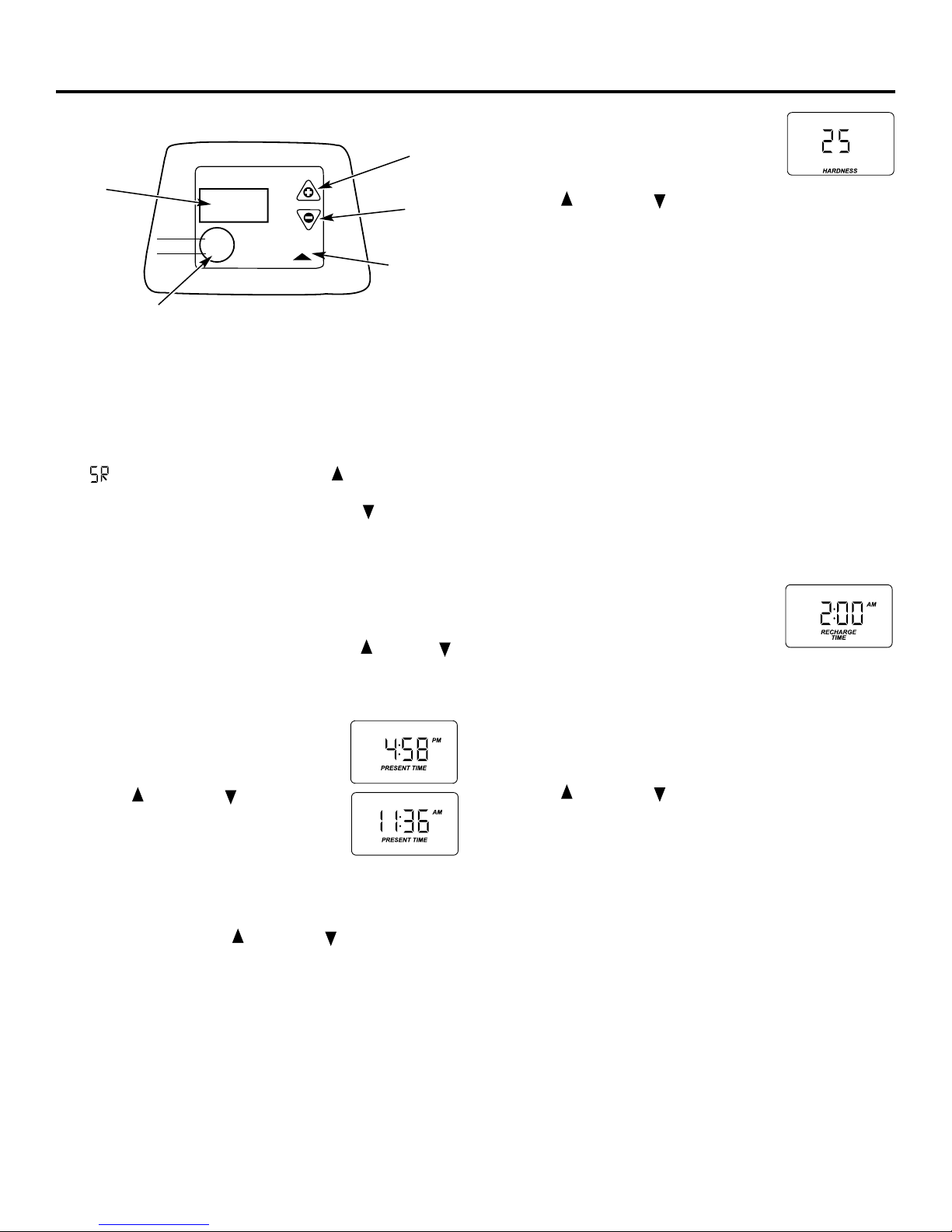
Programming the Control
CONTROL SETTINGS REQUIRED upon installation and
after an extended power outage.
NOTES:
■WHEN THE TRANSFORMER IS PLUGGED INTO THE
ELECTRICAL OUTLET, 12:00 PM (flashing), and PRESENT
TIME is displayed. Program the control as instructed below.
■If - - - or - - - - is flashing, use the UP button to set the
correct model code as follows: F35 for GNSF35. If you pass
by the correct code number, use the DOWN button.
Then press the SELECT button to accept the correct model.
■A “beep” sounds while pressing buttons for control
programming. One beep signals a change in the control
display. Repeated beeps mean the control will not accept
a change from the button you have pressed, and you should
select another button.
■To program the control, you will use the UP , DOWN
and SELECT buttons.
■Use the SELECT button to select the desired control function.
SET PRESENT TIME OF DAY
1. Press the SELECT button until PRESENT
TIME appears in the display.
2. Press UP or DOWN button to set.
The UP button advances the time; the
DOWN button moves the time in reverse.
2. If the present time is between noon and midnight, be sure
PM shows in the display. If the present time is between
midnight and noon, be sure AM shows in the display.
NOTE: Each press of an UP or DOWN button changes
the time by one minute. Holding the button changes the time
at a rapid rate.
3. When the present time is correct, press SELECT to accept.
SET WATER HARDNESS NUMBER
1. Press the SELECT button until
HARDNESS appears in the display.
2. Press UP or DOWN button to set your water hardness
number in the display. DOWN decreases the hardness value.
UP increases the hardness value.
NOTE: Each press of a button changes the display by 1, between
1 and 25. Above 25, the display changes 5 at a time (25, 30, 35,
etc.). Holding a button in changes the numbers at a rapid rate.
3. When the display shows your water hardness (in grains per
gallon), press SELECT to accept.
NOTE: If there is clear water iron in your water supply, you will
need to increase the hardness setting by 5 for each 1 ppm of
clear water iron in your water supply.
You can get the grains per gallon (gpg) hardness of your water
supply from a water analysis laboratory. If you are on a
municipal supply, call your local water department. Or call
Legend Technical Services, an independent laboratory, to
request a water hardness test kit at 1.800.826.8553, extension
47. If your report shows hardness in parts per million (ppm)
or milligrams per liter (mg/l), simply divide by 17.1 to get the
equivalent number of grains per gallon.
SET RECHARGE (STARTING) TIME
1. Press the SELECT button until
RECHARGE TIME appears in the display.
NOTE: A flashing 2:00 AM (factory default)
should show in the display. This is a good time for recharge
to start (takes about 2 hours) in most households because water
is not in use. HARD WATER is bypassed to house faucets
during recharge.
If no change is needed, go to step 3. To change the recharge
starting time, follow step 2.
2. Press UP or DOWN button to set the desired recharge
start time. Be sure to observe the AM or PM as you did when
setting the time of day.
NOTE: Each press of a button changes the time by 1 hour.
Holding the buttons in changes the time at a rapid rate.
3. Press the SELECT button to accept.
SmartWater Softener System
TOUCH
or
HOLD SELECT
TIME
HARDNESS
RECHARGE NOW
RECHARGE TONIGHT
Display
TOUCH or HOLD button
SELECT
button
DOWN (-)
button
UP (+)
button

9
Optional Control Settings
The controller display has several options and features.
SYSTEM/ELECTRONIC DIAGNOSTICS
This display contains system diagnostics
information to assist in troubleshooting
problems with the Water Softener. See
page 15.
To access the System Diagnostics, press and hold the SELECT
button for 3 seconds.
To return to the normal display, press the SELECT button 2 times.
SALT EFFICIENCY
When the SALT EFFICIENCY feature is ON, the unit will operate
at a salt efficiency of at least 4000 grains of hardness removed
per pound of salt. This mode of operation is the most efficient
setting for salt usage, because the system will tend to recharge
more often, with less salt usage. Turning the feature OFF will
tend to lengthen the time between recharge cycles, which will
provide the most efficient usage of water, but may use more
salt. The degree of difference between these two cycles is highly
dependent on the water usage and hardness at a particular
installation.
NOTE: California Regulations require this feature to be ON for
installations in California.
To access the Salt Efficiency, press and hold
the SELECT button for 3 seconds. The
System Diagnostics display will appear.
Press the SELECT button again and the Salt
Efficiency display will appear.
To change the setting, press the UP or
DOWN buttons to toggle the feature
ON or OFF. Press the SELECT button to
accept.
ERROR SIGNALS
If there is an error code detected, the display
will flash Err to signal that the softener
requires service.
See page 15 for information to assist in troubleshooting
error codes. Once the problem is corrected, disconnect the
transformer from the wall outlet momentarily, and plug it back
in. The normal display will appear. The motor may run for
several minutes, as the unit resets. If the problem is not
corrected, the error code will reappear in 8 minutes.
DAYS TO EMPTY
HARDNESS
E
DAYS TO EMPTY
HARDNESS
E
DAYS TO EMPTY
HARDNESS
OR

10
Fig. 8
Salt hole cover
removed
Hose
Brinewell
Brinewell
cover (remove
and add about
3/4 oz. bleach)
Water, about
3 gallons
NOTE: When the above sanitizing regeneration is over,
all remaining bleach is flushed from the conditioner
and your house COLD water supply is fully soft
immediately. However, your water heater is filled with
hard water and as hot water is used, it will refill with soft
water. When all the hard water is replaced in the water
heater, hot only and mixed hot and cold water will be
fully soft. If you want totally soft water immediately, after
the above regeneration, drain the water heater until the
water runs cold.
WARNING: If you do drain the water heater,
use extreme care as the hot water could cause burns.
Turn the water heater off prior to draining.
Sanitizing Procedures
Care is taken at the factory to keep your softener clean
and sanitary. Materials used to make the softener will not
infect or contaminate your water supply and will not cause
bacteria to form or grow. However, during shipping,
storage, installing and operating, bacteria could get into
the softener. For this reason, sanitizing as follows is
suggested when installing.
NOTE: Sanitizing is recommended by the Water Quality
Association for disinfecting.
Be sure to complete all installation steps, including
timer programming.
Remove the brinewell cover (see Fig. 8) and pour
about 3/4 ounce (11⁄2tablespoons) of common 5.25%
household bleach (Clorox, Linco, BoPeep, White Sail,
Eagle, etc.) in the softener brinewell.
Press the TOUCH/HOLD button and hold for 3 seconds
to start a recharge. This first recharge does
several
things: fills the salt tank to the water level needed,
gets
all the air out of the resin tank, makes the resin bed
ready for service. See the Recharging section.
If after sanitation, water from house faucet tastes salty
or has a slight color, this is a preservative from the
resin tank. Turn on the cold soft water faucets and
drain for a few minutes or until clear.
NOTE: This recharge takes about 2 hours.
4
3
2
1
Step-by-step installation instructions.

11
Specifications/Dimensions
This system conforms to NSF/ANSI 44 for the specific capacity claims as verified and substantiated by test data.
* Testing was performed using pellet grade sodium chloride as the regenerant salt.
** Efficiency rating is valid only at the lowest stated salt dosage. This softener was efficiency rated according to NSF/ANSI 44.
*** Extent of iron removal may vary with conditions. The capacity to reduce clear water iron is substantiated by WQA test data.
Use of Diamond Crystal®Red•Out®or Super Iron Out®will improve iron removal. Refer to Cleaning Iron Out of the Water
Softening System section.
**** Canada working pressure limits: 1.4–7.0 kg/cm2.
GNSF35Z
Rated capacity* (see rating label on water softener)
Rated efficiency** (see rating label on water softener)
Amount of high capacity resin (lbs/cu. ft) 48.9/.94
Resin tank nominal size (in., dia. x height) 9 x 40
Service flow rate (gpm) (see rating label on water softener)
Water supply maximum hardness (gpg) 100
Water supply maximum clear water iron (ppm)*** 9
Water pressure limits (min.–max. psi)**** 20–125
Pressure drop at rated service flow (psig) 14
Water temperature limits (min.–max.°F) 40–120
Water supply minimum flow rate (gpm) 3
Maximum flow rate to drain (gpm) 2.2
18–1/4″
40–1/2″
41–1/4″
48–3/4″
INLET-OUTLET
11–1/2″
3–3/8″
OUT
INLET

Service
When the
water softening system
is providing
soft water, it is called “Service.” During
service, hard water flows from the house
main water pipe into the
water softening
system
. Inside the
water softening system
resin
tank is a bed made up of thousands of tiny,
plastic resin beads. As hard water passes
through the bed, each bead attracts and
holds the hard minerals. This is called ion-
exchanging. It is much like a magnet
attracting and holding metals. Water without
hard minerals (soft water) flows from the
water softening system
and to the house
pipes.
After a period of time, the resin beads
become coated with hard minerals and they
have to be cleaned. This cleaning is called
regeneration, or recharge. Regeneration is
started at 2:00 AM (factory setting) by the
water softening system
control, and consists of
five stages or cycles. These are FILL, BRINING,
BRINE RINSE, BACKWASH and FAST RINSE.
12
Automatic Hard Water Bypass During Regeneration
For emergency needs, hard water is available
to the home during the regeneration cycles.
However, you should avoid using HOT water
because the water heater will fill with the
hard water.
Fill Backwash
Salt dissolved in water is called brine. Brine
is needed to clean the hard minerals from
resin beads. To make the brine, water flows
into the salt storage area during the fill stage
as shown.
Brining
During brining, brine travels from the
salt storage area into the resin tank. Brine
is the cleaning agent needed to remove
hard minerals from the resin beads. The
hard minerals and brine are discharged
to the drain.
The nozzle and venturi create a suction to
move the brine, maintaining a very slow
rate to get the best resin cleaning with the
least salt.
Brine Rinse
After a premeasured amount of brine is
used, the brine valve closes. Water continues
to flow in the same path as during brining,
except for the discontinued brine flow. Hard
minerals and brine flush from the resin tank
to the drain.
During backwash, water travels up through
the resin tank at a fast flow rate, flushing
accumulated iron, dirt and sediments from
the resin bed and to drain.
Fast Rinse
Backwash is followed by a fast flow of water
down through the resin tank. The fast flow
flushes brine from the bottom of tank, and
packs the resin bed.
After fast rinse, the
water softening system
returns to soft water service.
Soft water
OUT
Salt storage
tank (salt
not shown)
Brine
valve
Hard water
IN
Resin
tank
Resin
bed
Soft water
OUT
Hard water
IN
Salt
storage
tank
Fill
water
Brine
valve
Hard water
bypass OUT
Nozzle &
venturi
Hard water
IN
Brine
valve
Brine
Drain
Drain
Hard water
bypass OUT
Hard water
IN
Drain
Soft water
OUT
Hard water
IN
About the water softener system.

Cleaning the Nozzle and Venturi Assembly
A clean nozzle and venturi is needed for the water softening
system to work properly. This small unit makes the suction
to move brine from the salt storage area to the resin tank
during regeneration. If it becomes plugged with sand,
dirt, etc., the water softening system will not work and
you will get hard water.
To get to the nozzle and venturi, remove the water
softening system top cover. Be sure the water softening
system is in service cycle (no water pressure at nozzle and
venturi). Then, while holding the nozzle and venturi
housing with one hand, remove the cap. Lift out the
screen support and screen, then the nozzle and venturi.
Wash and rinse the parts in warm water until clean. If
needed, use a small brush to remove iron or dirt. Also
check and clean the gasket.
NOTE: Some models have a small flow plug located in the
nozzle and venturi, and/or a small cone-shaped screen
in the housing. Be sure to check and clean these parts,
if your model is so equipped.
Carefully replace all parts in the correct order. Lightly
lubricate the o-ring seal with clean silicone grease or
petroleum jelly and place in position. Install and tighten
the cap, by hand only. Do not overtighten the cap or housing.
IMPORTANT: Be sure small holes in the gasket are
centered directly over the small holes in the nozzle
and venturi housing.
*Install with numbered side up, concave side down.
Cap
O-ring seal
Screen support
Screen
Screen
Nozzle & Venturi
Nozzle & Venturi housing
Gasket
*Fill Flow plug
Breaking a Salt Bridge
Sometimes, a hard crust or salt bridge forms in the salt
storage area. It is usually caused
by high humidity or the
wrong kind of salt. When the salt bridges, an empty space
forms
between the water and salt. Then salt will not
dissolve in the water to make brine.
If the brine tank is full of salt, it is hard to tell if you have
a salt bridge. Salt is loose on top, but the bridge is under
it. The following is the best way to check for a salt
bridge.
Salt should be loose all the way to the bottom of the tank.
Take a broom handle or like
tool, and carefully push it
down into the salt, working it up and down. If the tool
strikes a
hard object (be sure it’s not the bottom or sides
of the tank), it’s most likely a salt bridge. Carefully break
the bridge with the tool. Do not pound on the walls of the
tank.
If the wrong kind of salt made the bridge, take it out.
Then fill the tank with nugget or pellet salt only. In
humid areas, it is best to fill with less salt, more often.
Push tool into salt
bridge to break
Pencil
mark
Broom
handle Salt
Salt
bridge
Water level
1″–2″
13
www.GEAppliances.com

14
About the water softener system.
During normal operation, the present time of
day and AM or PM show in the control display
area. When the demand computer determines
a recharge is needed, a regeneration (recharge)
begins at the next recharge start time. During
a recharge, RECHARGE NOW flashes until the
recharge is over.
Normal Operation, Control Displays
Sometimes, a manually started recharge may
be desired or needed. Two examples:
■You have used more water than usual
(house guests, extra washing, etc.) and
you may run out of soft water before the
next recharge.
■The system ran out of salt.
Use one of the following features to start
a recharge immediately, or at the next preset
recharge start time.
RECHARGE TONIGHT
Touch (do not hold) the TOUCH OR HOLD
button. RECHARGE TONIGHT flashes in the
control display area. A recharge will occur at
the next preset recharge start time. If you
decide to cancel this recharge, touch the same
button once more.
RECHARGE NOW
Press and hold the TOUCH OR HOLD button until
RECHARGE NOW starts to flash in the control
display area. The water softening system begins
an immediate recharge and, when over in
about two hours, you will have a new supply of
soft water. Once started, you cannot cancel this
recharge.
Feature: Optional Recharge Controls
Feature: Memory
If electrical power to the water softening system
is interrupted, the control display is blank, and
the blue indicator light is off, but the control
keeps correct time for about 6 hours. When
power is restored, you have to reset the present
time only if the display is flashing. All other
settings are maintained and never require
resetting unless a change is desired.
If the time is flashing after a long power outage,
the water softening system continues to work
as it should to provide you with soft water.
However, recharge may occur at the wrong time
of day until you reset the control to the correct
time of day.
The control computer has a self-diagnostic
function for the electrical system (except
input power and water meter). The computer
monitors the electronic components and
circuits for correct operation. If a malfunction
occurs, an error code appears in the
control display.
The chart on Error Codes shows the error codes
that could appear and possible reasons for each
code. See Manually Initiated Electronic Diagnostics
to further isolate the defect.
Feature/Service: Automatic Electronic Diagnostics

15
ERROR CODE DISPLAYED ERR 01 ERR 02 ERR 03 ERR 04 ERR 05
POSSIBLE DEFECT • Motor • Position • Motor • Position • Control
inoperative switch inoperative switch or
or wiring wiring
harness harness
• Wiring harness • Control • Control • Control
or connection
to switch
• Position switch
• Control
To remove an error code: 1. Unplug transformer.
2. Correct defect.
3. Plug transformer in.
4. Wait for at least 8 minutes. The error code will return if the reason for
the error code was not corrected.
NO SOFT
WATER
CONTROL SHOWS
WRONG TIME AND DAY,
AND/OR IS FLASHING.
CONTROL
DISPLAY
BLANK.
CONTROL DISPLAY SHOWS
CORRECT TIME AND DAY
AND IS STEADY.
Check electrical
power to control
(outlet, transformer,
power cable, all
connections).
Do manual
diagnostics.
NO POWER
POWER OK
REPAIR AS
NEEDED
CONTROL
DEFECTIVE
Do manual
diagnostics to
verify proper
function.
Electrical power was off.
Reset the correct time of
day.
Investigate reason for
power loss.
www.GEAppliances.com
Service: Electronic Demand Time Features and Service
If you are not getting soft water, and an error
code is not displayed, use the procedures below
to find the problem. First make the following
visual checks.
VISUAL CHECKS:
1. Is there electrical power to the outlet the
water softening system transformer is
plugged into?
2. Is there sufficient salt in the storage tank?
3. Is the softener bypass valve directing water
for soft water service?
4. Is the valve drain hose open to the drain,
not more than 8′above the softener, and
unobstructed? If hose is above 8′, see page 6,
section 4.
If you do not find a problem with the visual checks,
continue below.
Service: Timer/Softener, Service Checkout Procedure

16
1. To enter diagnostics, press and hold the
SELECT button until (000 – –) shows in
the display.
AThe first 3 digits indicate water meter
operation as follows:
■000 (steady) = soft water not in
use…no flow through the meter.
—OPEN A NEARBY SOFT WATER FAUCET—
■000 to 199 (continual) = repeats display for each
gallon of water passing through the meter.
If you don’t get a reading in the display, with faucet
open, pull the sensor from the valve outlet port. Pass
a small magnet back and forth in front of the sensor.
You should get a reading in the display. If you get a
reading, shut off water supply, unhook the in and out
plumbing and check the turbine for binding.
BThe letter (P) and dash(es) indicate POSITION switch
operation. The letter appearing means the switch is
closed; the dash means the switch is open. Use the
TOUCH OR HOLD (RECHARGE TONIGHT–RECHARGE NOW)
button to manually advance the valve into each cycle
and check correct switch operation.
CWhile in this diagnostic screen, the following information
is available and may be beneficial for various reasons.
This information is retained by the computer from the
first time electrical power is applied to the control.
■Press and hold the UP button to display the number
of days this control has had electrical power applied.
■Press and hold the DOWN button to display the
number of regenerations initiated by this control
since the SR code number was entered.
2. Press the SELECT button and hold in
three seconds until a Service Rating code
appears in the display.
For correct water softening system
operation, the model code must be F35 for model GNSF35Z.
To reset the code, press the UP or DOWN button until the
correct number shows.
3. Press the SELECT button to return to the present time
display. If the code was changed, make ALL the timer settings.
NOTE: If the control is left in a diagnostic display or a
flashing display when setting times or hardness, present time
automatically returns if a button is not pressed within four
minutes.
About the water softener system.
CORRECT SWITCH
DISPLAYS VALVE CYCLE STATUS
— — Valve in service, fill, brining, backwash
or fast rinse position.
— P Valve rotating from one position to another
Turbine Switches
Water
Meter (A)
Switch (B)
OR
Service: Manually Initiated Electronic Diagnostics
Motor
Turbine
Turbine support
and shaft
Sensor
housing
Position
switch
Valve
outlet

17
www.GEAppliances.com
This check verifies proper operation of the
valve motor, brine tank fill, brine draw,
regeneration flow rates and other controller
functions. First, make the initial checks and
the Manually Initiated Electronic Diagnostics.
NOTE: The control display must show a steady
time (not flashing).
1. Press the TOUCH OR HOLD button and hold in
for three seconds. RECHARGE NOW begins to
flash as the water softening system enters the
fill cycle of regeneration. Remove the
brinewell cover and, using a flashlight,
observe fill water entering the brine tank.
If water does not enter the tank, look for
an obstructed nozzle, venturi, fill flow
plug or brine tubing.
See Care and cleaning of the water softening
system section.
2. After observing fill, press the TOUCH OR HOLD
button to move the water softening system
into brining. A slow flow of water to the drain
will begin. Verify brine draw from the brine
tank by shining a flashlight into the brinewell
and observing a noticeable drop in the liquid
level over an extended period of time.
NOTE: Be sure a salt bridge is not preventing
water from contacting salt. See Care and
cleaning of the water softening system section.
If the water softening system does not draw brine,
check:
■nozzle and/or venturi dirty or defective.
■nozzle and venturi not seated properly
on gasket.
■restricted drain (check drain fitting and
hose).
■defective nozzle and venturi seal.
■other inner valve defect (rotor seal, rotor
and disc, wave washer, etc.).
NOTE: If water system pressure is low, an
elevated drain hose may cause back pressure,
stopping brine draw.
3. Again, press the TOUCH OR HOLD button
to move the water softening system into
backwash. Look for a fast flow of water from
the drain hose. A slow flow indicates a
plugged top distributor, backwash flow plug
or drain hose.
4. Press the TOUCH OR HOLD button to move the
water softening system into fast rinse. Again
look for a fast drain flow. Allow the water
softening system to rinse for a few minutes
to flush out any brine that may remain in
the resin tank from the brining cycle test.
5. To return the water softening system to
service, press the TOUCH OR HOLD button.
Service: Manually Advance Regeneration Check

Checking the Salt Storage Level and Refilling
Brine (salt dissolved in water) is needed for each
and every regeneration. The water for making
brine is metered into the salt storage area by the
water softening system valve and control. However,
you must keep the tank supplied with salt.
When to refill with salt: Check the salt level a few
weeks after you install the water softening system
and every week after that. Refill when the brine
tank is from 1/3 to 1/2 full. In humid areas it is
best to fill with less salt more often. Never allow the
water softening system to use all the salt before you
refill it. Without salt, you will soon have hard water.
Use clean water softening salts only, at least 99.5%
pure. NUGGET, PELLET or coarse SOLAR salts are
recommended. Do not use rock, block, granulated or
ice cream-making salts. They contain dirt and
sediments, or mush and cake, and will create
maintenance problems.
CAUTION: Water softening salt with iron
removing additives: Some salts may have an additive to
help the water softening system handle iron in the water
supply. Although this additive may help to keep the water
softening system resin clean, it may also release corrosive
fumes that weaken and shorten the life of some water
softening system parts. GE recommends using only
Diamond Crystal®Red•Out®brand salt.
Your water softening system takes hardness
minerals (calcium and magnesium) out of the
water. Also, it can control some (see Specification
Guidelines section) “clear water” iron. With clear
water iron, water from a faucet is clear when first
put into a glass. After 15 to 30 minutes, the water
begins to cloud or turn rust-colored. A water
softening system will not remove any iron that
makes the water cloudy or rusty as it comes from
the faucet (called red water iron). To take red
water iron out of water, or over the maximum of
clear water iron, an iron filter or other equipment
is needed.
GE recommends using only Diamond Crystal®
Red•Out®brand salts with Iron Fighter®additive to
help keep the resin bed clean of clear iron. If your
water supply has clear water iron, periodic resin
bed cleaning is needed. GE recommends using
Super Iron Out®brand resin bed cleaner to
thoroughly clean your resin bed if your iron
content is high. Clean the bed at least every six
months, or more often if iron appears in the soft
water between cleanings.
IMPORTANT: It is important to mix the resin bed
cleaner with water (following the manufacturer’s
instructions), pour it into the brinewell tube (see
page 5) and regenerate the softener immediately.
Do not pour the resin bed cleaner in with the salt,
since it will not be as effective in cleaning the resin
and can cause damage to the softener if it is left in
the brine tank for an extended period due to the
corrosive gases that are formed.
Cleaning Iron Out of the Water Softening System
18
Care and cleaning of the water softening system.

19
Troubleshooting Tips
Save time and money! Review the chart on this
page first and you may not need to call for service.
Problem Possible Causes What To Do
No soft water Faucet or fixture where sample was •
To conserve salt, the installer
may have isolated some fixtures
taken not plumbed to soft water.
(outside faucets, toilets, etc.)
from soft water. From the outlet
NOTE:
Be sure sample is from a faucet of the water softening system, trace the water flow path in
that does not mix soft and hard water. house plumbing. If soft water is not directed to a faucet or
For example, a single lever kitchen faucet
fixture where wanted, consult a plumber.
if the cold side is plumbed to hard water.
No salt in the storage tank. •Refill with salt. See the Step-by-Step Installation Instructions.
Use the TOUCH OR HOLD button to start a regeneration.
See the About the water softener system section.
Salt in storage tank bridged. •See the Breaking a Salt Bridge section.
Transformer unplugged at wall outlet
•Check for a loss of electrical power to the water softening
or
power cable to softener not system due to any of these conditions and correct as needed.
connected. Fuse blown or circuit With the power supply restored, observe the faceplate time
breaker popped on circuit to electrical display and read Program Memory section.
outlet. Electrical outlet on a circuit that
NOTE: The electrical outlet for the softener should be continuously
can be switched off.
live
so it cannot be accidentally switched off.
Manual bypass valve in bypass •Be sure the bypass valve stem
is positioned properly, with the
position.
knob in the OUT position. Observe i
nstructions on the decal
at the end of the stem.
Valve drain hose pinched, plugged, •
Any restriction in this drain hose
may prevent proper operation
elevated too high or otherwise
of the
nozzle and venturi and reduce or prevent brine draw
restricted. during regenerations.
Nozzle and venturi dirty, incorrectly •Refer to Cleaning the Nozzle and Venturi Assembly
instructions.
assembled or damaged.
With water pressure to the
water softening system off, take the
nozzle assembly apart. Inspect, clean and replace as needed.
Any foreign particle(s), scratches, nicks, etc., in the passages
can
prevent operation. Be sure holes in the gasket are centered
over holes in the housing.
NO SOFT WATER—Most Common Problems:
Check the following before calling for service
•Salt in softener—at least 1/3 full.
•Bypass valve in “Service” position. Knob should be in the OUT position.
•Check hardness setting in control. Verify hardness of supply water.
Water hardness can vary throughout the year.
•Salt Bridge, water not in contact with salt (see Breaking a Salt Bridge section).
Before you call for service. . . www.GEAppliances.com

Troubleshooting Tips
Problem Possible Causes What To Do
Water hard sometimes Using hot water while the water •Avoid using hot water during water softening system
softening system is regenerating regenerations because the water heater will refill with
hard water. See Automatic Hard Water Bypass During
Regeneration section.
Too few regenerations or more •See Regeneration Chart for correct setting.
water being used
Grains of hardness in your water •
Water hardness can change
over time, especially in well water.
supply have increased To check, have the water tested by a water analysis laboratory
or call your local water department. Adjust the timer
settings as needed. See Regeneration Chart.
Water feels slippery Absence of hardness minerals •This is normal.
after installation of
water softening system
Water softening system Possible salt bridge •See the Operating Instructions, Tips section.
not using any salt
Possible plugged nozzle and venturi •See the Operating Instructions, Tips section.
Water is blue color Acidic water in copper plumbing •Have the water tested at once.
after water softening
system was installed
Water softening system Meter turbine stuck •See the Service: Manually Inititated Electronic Diagnostics
not regenerating section for troubleshooting procedures, page 16.
•Call for service.
Sensor wire corroded •See the Service: Manually Inititated Electronic Diagnostics
section for troubleshooting procedures, page 16.
•Call for service.
No power to unit •Check the circuit breaker or fuses.
Mechanical defect •Call for service.
Cloudiness on glassware Combination of soft water and •This is called etching and is permanent. To prevent this
(automatic dishwashers) too much detergent from happening, use less detergent if you have soft water.
Wash glassware in the shortest cycle that will get them clean.
Salty tasting water Insufficient backwash and •Press and hold TOUCH or HOLD button until RECHARGE
after installation rinse time starts to flash to start a regeneration.
•At completion of regeneration cycle (approx. 2 hrs), run
water from faucets to purge the salty water.
Low water pressure •Check pressure; should be minimum 20 psi.
Restricted drain hose •Clean and reconnect hose.
20
Before you call for service. . .
Table of contents