1、STRUCTURE, FEATURES AND USAGE
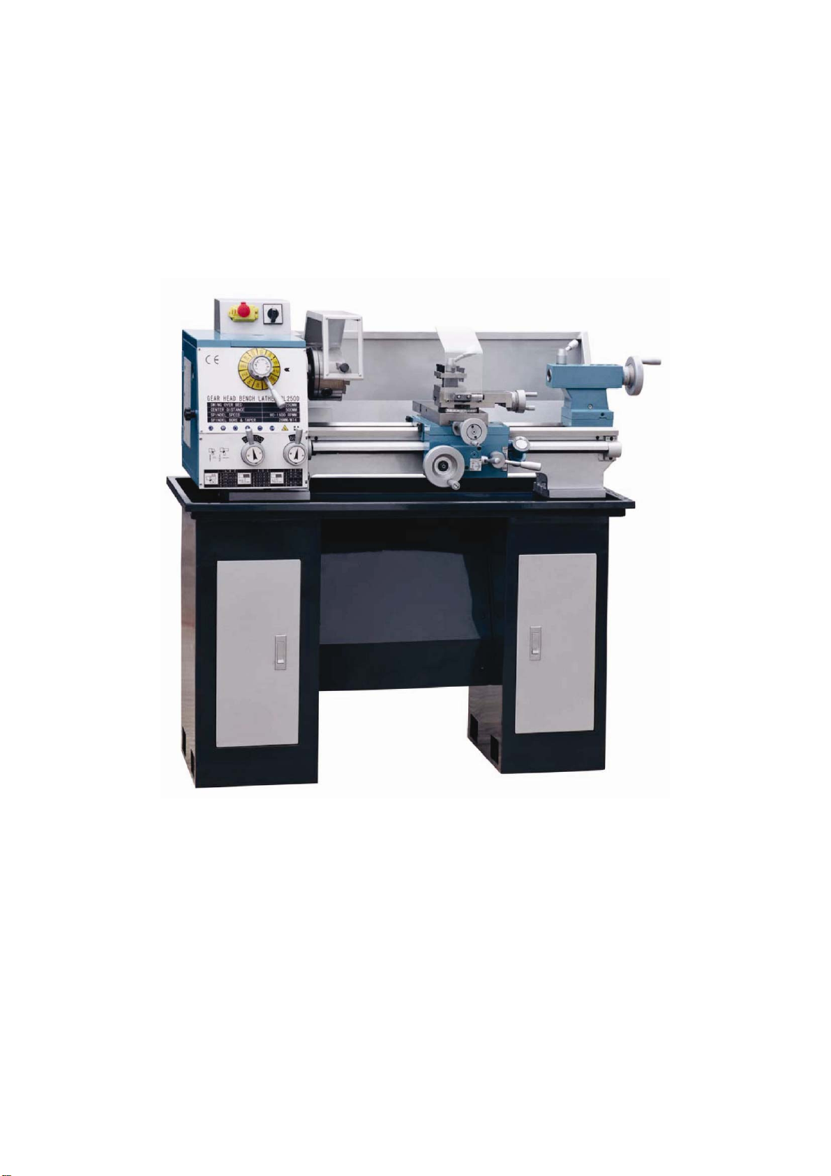
This lathe adopts full gear transmission with great stability and high tooling
accuracy. The main spindle speed changing unit –diprosopia curves disc, and
longitudinal/cross feeding safety unit are own patented. The full functioned
lathe with longitudinal/cross auto-feeding can realize tooling speeds choosing
and regular threads setting through feeding box.
1
2
C
B
A
1
2
3
4
5
A B C A B C A B C
5
4
3
2
1
5
4
3
2
1
5
4
3
2
1
0.50 1.00 2.50
0.40
0.35
0.30
0.25
0.80
0.70
0.60
0.50
2.00
1.75
1.50
1.25
48 24
60 30 12
80 40 16
96 48
mm n/1″
mm
CJM250
0.035 0. 070.175
0.045 0. 090.225
0.050. 100.25
0.060. 120.30
0.075 0. 150.375
O
F R
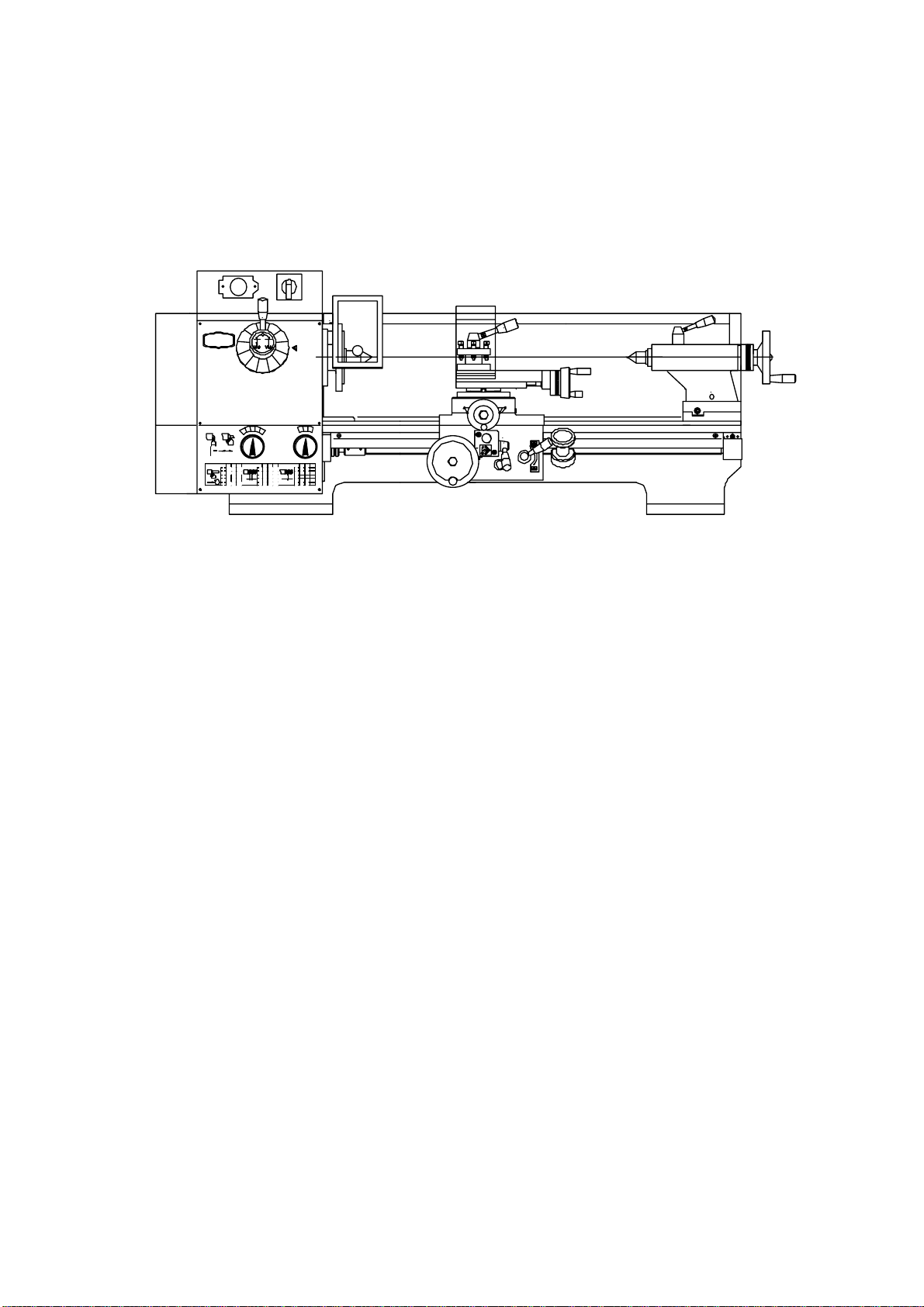
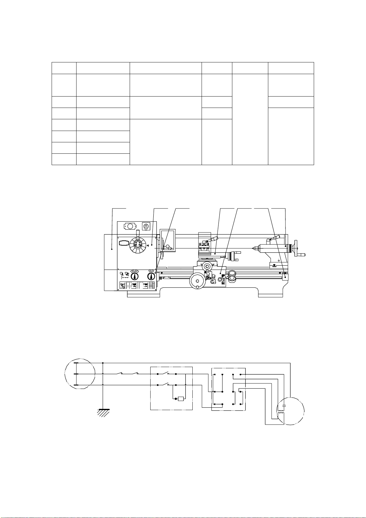
Picture 1 OVERVIEW
) Headstock Full gear driven, the spindle speed changing is achieved
through sliding gears and the main spindle can get 12 kinds of speeds
at wide range.The lathe has the structure of forward/reward feeding
unit which can get auto feeding in both direction and make right/left
threading.
) Gearbox Transmit the movement in headstock to feeding box through
change gears. By choosing different change gears, different
metric/imperial threading can be achieved.
) Feeding box It has 15 shifts. There is no need of changing the gears
to get 15 kinds of feeding speed and tooling 15 kinds of
metric/imperial threads.
)Carriage It has longitudinal/cross feeding interlock unit which
can make auto feeding in longitudinal or cross direction.
) Bedway The bedway adopts two V guideways, ensuring perfect
positioning accuracy and excellent tooling rigidity.
)Tailstock
It adopts rapid cam-lock unit to make easy and rapid operation.
) Standard accessories
Three jaw chuck, dead center, toolpost wrench, inner hexagon spanner,
stud dead spanner, change gears, splash guard
) Optional accessories for your choice
Machine stand, steady rest, follow rest, oil tray, toolcutter set,
live center, face plate, four jaw chuck, backplate, special gears.