manuals.online logo
Brands
  1. Home
  2. •
  3. Brands
  4. •
  5. Geax
  6. •
  7. Tractor Accessories
  8. •
  9. Geax EK75CFAJ160 Use and care manual

Geax EK75CFAJ160 Use and care manual

OPERATION AND SAFETY
MANUAL
Rev.01/17
GEAX
s.r.l.
EK75CFAJ160
Serial number :
160J075E
GEAX
s.r.l via Campoceraso,13
60027 Osimo (AN) ITALY
Tel. +39/0717131953
Fax. +39/071715199
www.geax.it [email protected]
GEAX
s.r.l Chapter 1
OPERATOR TRAINING
1
Chapter 1
OPERATOR TRAINING
1.1 Foreword
This manual provides information to operators on the features and operation
of the EK75 track-mounted drilling rig. It also describes the hazards relating to
the rig's operation and what to do to minimize the risks. The purpose of this
manual is to prepare safety-minded operators; accordingly, as well as listing
the required procedures, it is designed to raise the reader’s awareness on the
importance of working safely. Our is that it will contribute to eliminate
superficial, careless and uncritically repetitive behaviours, which are
ultimately the main causes of jobsite accidents.
1.2 Physical and mental conditions of operators
Operators must have past experience in the sector, be familiar with the
general safety rules and have proven their attitude to recognize and handle
potentially dangerous situations. Before using the (EK75
1
) drilling rig for the
first time, new operators must read this OPERATION AND SAFETY MANUAL
completely. Once they are sure they have understood it, they can proceed to
use the rig with the assistance of an experienced colleague. The introductory
period should last as long as necessary, depending on the operator’s past
experience.
At the time of starting a work shift, operators must be in good health and in
sound physical and mental conditions. Their blood alcohol content must be
within the levels prescribed by motor vehicle regulations.
1.3 Operators' equipment
Operators must wear the protective equipment required by jobsite safety
regulations and relating to the specific activities carried out, e.g.:
•type-approved helmet
•type-approved safety shoes
•comfortable, appropriately-sized work overalls
•close-fitting, type-approved protective gloves
•type-approved safety glasses
•type-approved earplugs or earmuffs
•protective face masks (when required by working conditions)
1
Make sure the serial number on the drilling rig is the same as the number printed in the manual.
GEAX
s.r.l Chapter 1
OPERATOR TRAINING
2
All protective clothing and devices must be in good conditions and clean
enough not to affect their protection capacity or wearing comfort. In particular,
heavy clothing must be used as required by the temperature on the jobsite:
thermal comfort contributes to keeping the attention threshold high. Overalls
should have no loose flaps that might hamper the operation of controls or get
caught on edges or rotating shafts. Gloves are necessary to protect the
hands from cuts and abrasions that can be produced when gripping wire
ropes or metal parts, but they should not reduce finger mobility nor get caught
on edges or on the controls. Avoid wearing rings or jewellery.
1.4 Safety signs
A poster should be placed in the jobsite with safety signs reminding to wear
the protective devices described above, as required by law. Figure 1.4.1
shows a few of these mandatory signs.
Fig. 1.4.1
GEAX
s.r.l Chapter 1
OPERATOR TRAINING
3
1.5 Symbols used in this manual
Danger (or other) signs are used at various points in the manual to call the reader’s
attention to issues regarding potentially dangerous activities.
Situation, procedure, context or other factor that can lead to increased risk.
Situation, procedure, context or other factor that can lead to increased risk of
electrocution.
Situation, procedure, context or other factor that can lead to increased risk of
getting caught and dragged by rotating parts.
Situation, procedure, context or other factor that can lead to increased risk of
fire.
Situation, procedure, context or other factor that can lead to increased risk of
scalding on parts that become hot during operation.
Situation, procedure, context or other factor that can lead to increased risk of
intoxication or poisoning by harmful substances.
Situation, procedure, context or other factor that can lead to increased risk of
intoxication or poisoning by harmful substances.
Situation, procedure, context or other factor that can lead to increased risk of
burning by corrosive substances.
Situation, procedure, context or other factor that can lead to increased risk of
loss of balance and falling.
Situation, procedure, context or other factor that can lead to increased risk of
crushing hands.
Situation, procedure, context or other factor that can lead to increased risk of
being hit by suspended loads falling down.
Improving safety measures is a never-ending task; should you encounter a potentially
hazardous situation that is not adequately covered in this manual, please let us know.
GEAX
s.r.l. Chapter 2
TRANSPORTING THE DRILLING RIG
1
Chapter 2
TRANSPORTING THE DRILLING RIG
2.1 Operations preparing transportation
2.1.1 Removing the tool
The auger tool (two parts + the tip) can only be disassembled with the mast
upright. Disassemble the tip, the lower part and then the upper part.
Proceed as follows to disassemble the tip:
Lower the tool to the ground.
Disassemble the centring device using the winch 2° to handle the parts
(70 kg.) fig. 2.2.3.1.
Hook the tip to the rope of the secondary winch.
Command a slight tensioning of the rope.
Loosen the recessed safety bolt and slip the pin off.
Lift the rotary so that the joint slips off and the tip remains hanging on
the rope of the winch.
Move the rope of the secondary winch down.
Place the tip on the ground and move it.
Proceed as follows to disassemble the central part of the auger fig.2.1.1.1:
 Lower the tool to the ground.
 Lean the ladder against the mast.
 When a second operator at the base guarantees the stability of the
ladder by holding it with both hands, climb up to the height of the joint
and secure the safety belts to the eyebolt on the mast.
GEAX
s.r.l. Chapter 2
TRANSPORTING THE DRILLING RIG
2
 Hook the tool (lower element) to the rope of the secondary winch.
 Command a slight tensioning of the rope.
 Loosen the recessed safety bolt and slip the pin off.
 Climb down the ladder and remove it.
 Go to a safe area.
Lift the rotary-tool so that the joint slips off and the auger part remains
hanging on the rope of the winch.
 Move the rope of the secondary winch down.
 Place the tool on the ground and move it.
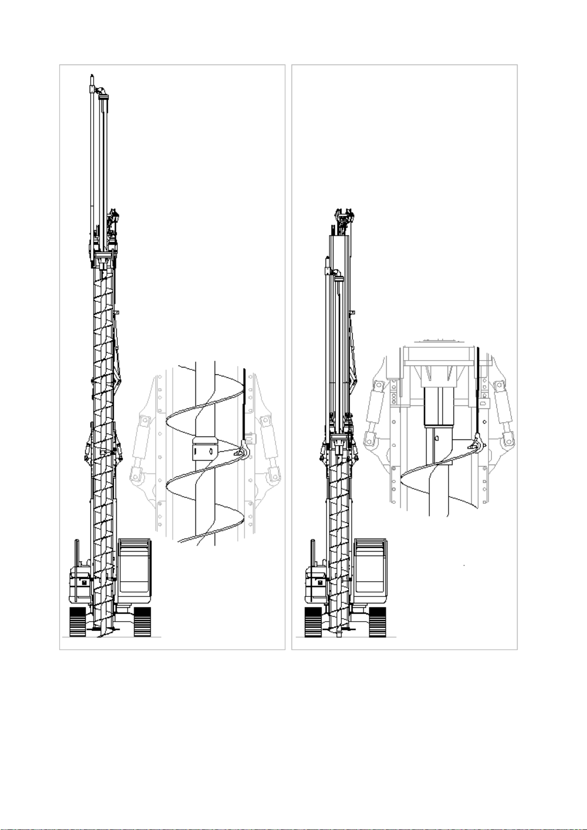
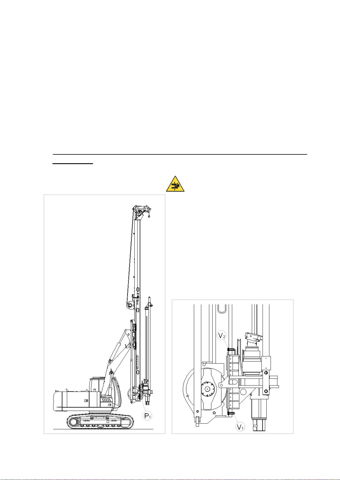
Proceed as follows to disassemble the upper part of the auger fig.2.1.1.2:
 Rest the tool on the ground, moving the rotary to the intermediate
position.
 Lean the ladder against the mast.
 When a second operator at the base guarantees the stability of the
ladder by holding it with both hands, climb up to the height of the rotary
joint and secure the safety belts to the eyebolt on the mast.
 Hook the tool (upper element) to the rope of the secondary winch.
 Command a slight tensioning.
 Loosen the recessed safety bolt and slip the pin off.
 Climb down the ladder and remove it.
 Go to a safe area.
 Lift the rotary-shaft so that the joint slips off and the auger remains
hanging on the rope of the winch.
Move the rope of the secondary winch down.
Place the tool on the ground and move it.
GEAX
s.r.l. Chapter 2
TRANSPORTING THE DRILLING RIG
3
fig.2.1.1.1 fig.2.1.1.2
2.1.2 Disassembly of mast support extension.
Before folding the mast, the support extension must be disassembled
GEAX
s.r.l. Chapter 2
TRANSPORTING THE DRILLING RIG
4
2.1.3 Closing mast for travel configuration
Proceed as follows to fold the mast:
1. Lower the rotary to the point indicated in fig.2.1.3.1.
2. Position the pin V1on the rotary guide to block downward sliding
fig.2.1.3.2;
3. Deactivate the down limit switch of winch 1°.
4. Lower the rotary until it rests on the pin V1.
5. Further loosen the rope (30 cm.) to avoid problems when folding the
mast.
6. Position the pin V2.
7. Fold the mast forwards, acting alternately on the joystick D1 and
selector D2.
8. Reach the position shown in fig.2.1.3.3.
fig.2.1.3.1 fig.2.1.3.2
GEAX
s.r.l. Chapter 2
TRANSPORTING THE DRILLING RIG
5
9. Remove the bolts and two pins B between the two parts of the mast
fig.2.1.2.3.
fig.2.1.3.3
10.Make sure no one is in the trajectory of the folding mast fig.2.1.3.4.
11.Act on the selector D3 to fold the mast.
fig.2.1.3.4
12.Insert the bolt A to block movement of the mast fig.2.1.3.4.
13.Take on the configuration shown in fig.2.3.2.1 to load the machine onto
the transportation vehicle.
GEAX
s.r.l. Chapter 2
TRANSPORTING THE DRILLING RIG
6
2.2 Setting up drilling rig at jobsitesite
2.2.1 Opening mast for work configuration
Proceed as follows to open the mast:
 Remove the bolt A between the two parts of the mast.
 Make sure no one is in the trajectory of the opening mast.
 Act on the selector D3 to open the mast.
 If the mast has difficulty moving, the operator can intervene to detach it
making sure his body remains outside of the trajectory of the mast
fig.2.2.2.1.
fig.2.2.1.1
 Make sure the ropes are not damaged while the mast is rotating.
 When the mast is aligned, insert the pins B and the bolts between the
two parts and secure them fig.2.1.2.3.
 Make sure the ropes are positioned correctly on the pulleys.
 Lift the rotary slightly to be able to pull the blocking pins off.
 Pull off the blocking pins.
GEAX
s.r.l. Chapter 2
TRANSPORTING THE DRILLING RIG
7
Align the mast vertically by acting alternately on the joystick D1 and on
the selector D2, being careful not to scrape the base of the mast
against the ground.
Act on the joystick D1 to achieve the perfect upright position of the
mast.
Re-activate all limit switches.
2.2.2 Assembling tool
The auger tool (in two parts + the tip) can only be assembled with the mast
upright. Assemble the upper part, the central part and then the tip.
Proceed as follows to assemble the upper part:
1. Move the rotary to the intermediate position P2fig. 2.2.2.1.
Fig. 2.2.2.1
GEAX
s.r.l. Chapter 2
TRANSPORTING THE DRILLING RIG
8
2. Hook the tool (upper element) to the rope of the secondary winch.
3. Go to a safe area.
4. Lift the tool until the two parts of the joint are aligned.
5. Lean the ladder against the mast.
6. When a second operator at the base guarantees the stability of the
ladder by holding it with both hands, climb up to the height of the rotary
joint and secure the safety belts to the eyebolt on the mast.
7. Push the tool so that the male and female parts of the joint are aligned
both axially and with the surfaces of the hexagon.
8. Lower the rotary-shaft to compose the joint.
9. Insert the pin and secure the safety bolt.
10.Climb down the ladder and remove it.
Proceed as follows to assemble the central part of the auger fig.2.1.1.1:
 Position the rotary at the up limit switch.
 Hook the tool (lower element) to the rope of the secondary winch.
 Lift the tool until the two parts of the joint are aligned.
 Lean the ladder against the mast.
 When a second operator at the base guarantees the stability of the
ladder by holding it with both hands, climb up to the height of the joint
and secure the safety belts to the eyebolt on the mast.
 Push the tool so that the male and female parts of the joint are aligned
both axially and with the surfaces of the hexagon.
 Lower the rotary to compose the joint.
 Insert the pin and secure the safety bolt.
 Climb down the ladder and remove it.
GEAX
s.r.l. Chapter 2
TRANSPORTING THE DRILLING RIG
9
Proceed as follows to assemble the tip:
1. Hook the tip to the rope of the secondary winch.
2. Lift the tip a bit off the ground.
3. Rest the tip on the ground so that the parts of the joint are aligned both
axially and with the surfaces of the hexagon.
4. Lower the rotary-tool so that the parts of the joint meet.
5. Insert the pin and secure the safety bolt.
6. Unhook the rope of the winch.
In the work configuration, the winch 2° rope must be hooked to the
specific eyebolt and slightly tensioned.
2.2.3 Assembling mast extension and centring device
When the drilling rig has been set up, before beginning the work shift the
lower mast support extension and the centring device of the tool must be
assembled. Use the winch 2° to handle the components (70 kg).
GEAX
s.r.l. Chapter 2
TRANSPORTING THE DRILLING RIG
1
0
Fig. 2.2.3.1
2.3 Loading, unloading and anchoring the rig on a semitrailer
2.3.1 Positioning the semitrailer
The trailer must be placed on level ground, firm enough to allow
using the loading ramps and performing the manoeuvres required to
align the rig to the ramps. The climb must be straight and in line with
the trailer.
Make sure there are no obstacles or overhead cables inside the drilling rig’s
manoeuvring space, paying special attention if the mast must be positioned
vertically (fig.2.4.1.2).
2.3.2 Loading and unloading
When loading or unloading the rig on/from the trailer, the rig’s
configuration must be as shown in fig. 2.3.2.1 with the tool detached
and the mast folded down. This configuration is similar to the
transport configuration, except that the boom is slightly raised to prevent the
rotary's bottom flange from scraping on the ground or on the deck (a 20-30
cm clearance is sufficient).
Figures 2.3.2.1-2-3-4-5-6 show the loading operation sequence.
GEAX
s.r.l. Chapter 2
TRANSPORTING THE DRILLING RIG
1
1
fig.2.3.2.1
fig.2.3.2.2
Figures 2.3.2.2 and 2.3.2.11 show the approximate point where the rig changes
inclination when passing from the ramp to the deck or vice versa. In this
stage the rig should travel at its lowest speed so that the change occurs as
gently as possible.
fig.2.3.2.3
GEAX
s.r.l. Chapter 2
TRANSPORTING THE DRILLING RIG
1
2
fig.2.3.2.4
fig.2.3.2.5
fig.2.3.2.6
GEAX
s.r.l. Chapter 2
TRANSPORTING THE DRILLING RIG
1
3
Figures 2.2.2.7 -8-9-10-11 show the unloading operation sequence.
fig.2.3.2.7
fig.2.3.2.8
fig.2.3.2.9
GEAX
s.r.l. Chapter 2
TRANSPORTING THE DRILLING RIG
1
4
fig.2.3.2.10
fig.2.3.2.11
To climb the slope use the ramps supplied, placing them so that their length
and rigidity are compatible with the rig's gradeability and weight. Place the
trailer on a sufficiently wide, flat area, free from overhead cables (power lines
or other) that might interfere with loading/unloading.
Making contact with power lines is particularly dangerous because (in
addition to the mechanical aspects described below) it can cause an
electric shock to persons who are touching metal parts (e.g., the
trailer or the drilling rig) and the ground at the same time. In case of contact
with power lines do not touch the vehicles involved (especially the trailer, as it
has rubber tires). If the cable remains in contact with the rig, the operator
should stay inside and await the intervention of the power company
personnel. If the operator tries to get off the rig there is a chance that he
might come in contact with the vehicle and the ground at the same time,
receiving a dangerous electric shock. The risk is greatest when the rig is on
the trailer, because the rubber tires provide insulation from the ground and
allow very high voltages. If the rig is on the ground the risk is smaller, since
the drilling rig is mounted on metal tracks. Non-electric cables pose risks of a
mechanical nature. They might be strong enough to topple supporting
GEAX
s.r.l. Chapter 2
TRANSPORTING THE DRILLING RIG
1
5
structures before breaking, causing danger to bystanders. After breaking,
they might whip around violently as they release the elastic energy
accumulated.
During loading and unloading, persons on the ground should stay at
a safe distance.
2.3.3 Anchoring
The drilling rig must be anchored to the semitrailer with strong stay wires
capable of preventing any movement.
2.4 Transportation
2.4.1 Configuration for transportation on semitrailer
During transportation the drilling rig must be arranged in the
configuration shown in figure 2.4.1.1 or with the mast facing
backwards.The front part of the mast should rest on the deck of the
semitrailer in order to minimise the load on the boom’s hydraulic cylinders
and increase overall stability. The tool must be detached. The engine must be
turned off and the key on the dashboard turned to OFF. The door must be
secured shut to avoid it opening during transportation.
fig.2.4.1.1
Figure 8.4.2.1 shows the overall dimensions of the rig in its typical transport
configuration.
When the drilling rig is on the trailer deck, rotating the cab with
respect to the crawler must be done with the mast held vertical
and close to the cab, as shown in fig.2.4.1.2.

Popular Tractor Accessories manuals by other brands

Craftsman 486.24586 owner's manual

Craftsman

Craftsman 486.24586 owner's manual

Toro BU-003867 Operator's manual

Toro

Toro BU-003867 Operator's manual

pewag Bluetrack Mounting instruction

pewag

pewag Bluetrack Mounting instruction

matev SCA-130 operating manual

matev

matev SCA-130 operating manual

Degelman Landroller Operator's & parts manual

Degelman

Degelman Landroller Operator's & parts manual

Camoplast ATV T4S manual

Camoplast

Camoplast ATV T4S manual

Homelite 172 Assembly instructions and parts list

Homelite

Homelite 172 Assembly instructions and parts list

Westfalia ECO instruction manual

Westfalia

Westfalia ECO instruction manual

Kellfri 32-S500 operating instructions

Kellfri

Kellfri 32-S500 operating instructions

Tiger KUB M6-101 Mounting and operating instructions

Tiger

Tiger KUB M6-101 Mounting and operating instructions

Grouser Products 1300 Groomer Owner's manual & parts book

Grouser Products

Grouser Products 1300 Groomer Owner's manual & parts book

MK Martin MK Series Operator's & parts manual

MK Martin

MK Martin MK Series Operator's & parts manual

Degelman PRO-TILL 41 quick start guide

Degelman

Degelman PRO-TILL 41 quick start guide

Landoll 850 FINISHOLL Series Operator's manual

Landoll

Landoll 850 FINISHOLL Series Operator's manual

Bercomac BERCO 79974 owner's manual

Bercomac

Bercomac BERCO 79974 owner's manual

TMI HORNET 5600 Operation & installation manual

TMI HORNET

TMI HORNET 5600 Operation & installation manual

Femco WEATHERBRAKE 2186 instructions

Femco

Femco WEATHERBRAKE 2186 instructions

Walker A10 Operator's manual

Walker

Walker A10 Operator's manual

manuals.online logo
manuals.online logoBrands
  • About & Mission
  • Contact us
  • Privacy Policy
  • Terms and Conditions

Copyright 2025 Manuals.Online. All Rights Reserved.