HOLMS SP User manual

Original language: Swedish © HOLMS INDUSTRI AB, ALL RIGHTS RESERVED 140214. English
Operating instructions
Box 924 SE-591 29 Motala Sweden +46 141 22 41 00 ¬+46 141 22 41 90
Applicable from machine no.: 10985
2.50 m/3.0 m/3.5 m
Holms SP
Hydraulic sweeper roller


Holms SP
© HOLMS INDUSTRI AB, ALL RIGHTS RESERVED 140214. 3
Warning labels..............................................................4
Safety...........................................................................7
Product data.................................................................9
Machine identification plate...............................10
Product description.....................................................11
Standard model.................................................11
Optional extras..................................................11
Transport and storage................................................12
Operating instructions ................................................13
Settings.............................................................13
Operation....................................................................14
Electrohydraulic angling....................................15
Disconnection from carrier................................15
Sprinkler system (optional extra) ......................15
Service and maintenance...........................................16
After operation ..................................................16
Lubrication ........................................................16
Replacement of brush.......................................16
Index...........................................................................18
Contents

Holms SP
4© HOLMS INDUSTRI AB, ALL RIGHTS RESERVED 140214.
Warning labels
There are several specific warning labels on this product; see the descriptions below. Make sure that
you understand the implications of these labels before using the product.
Clean/replace warning labels if they are illegible or are missing. Contact you Holms dealer if you
require new labels.
Risk of crushing - mind your hands and do not come too close to the machine (warning label
1530052)
Do not enter this area whilst the machine is in
operation. Mind your hands and keep them away
from this area whilst the tool is in use.
Keep a safe distance away from the machine
whilst it is in operation. Not following this rule
may lead to serious personal injury or, in a worst
case scenario, death.
Risk of crushing - do not come too close to the machine (warning label 1530053)
Keep a safe distance away from the machine
whilst it is in operation. Not following this rule
may lead to serious personal injury or, in a worst
case scenario, death.

Holms SP
© HOLMS INDUSTRI AB, ALL RIGHTS RESERVED 140214. 5
Always read instructions and safety regulations before use (warning label 1530054)
Do not use the tool before you have thoroughly
studied all instructions and safety regulations,
and are sure you have understood them. If there
is something you do not understand, contact your
Holms dealer. Misinterpretations may result in
serious personal injury or, in a worst case
scenario, death.
Risk of crushing, beware of flying objects - mind your hands and do not come too close to the
machine (warning label 1530055)
Keep a safe distance from the tool whilst it is
being used and beware of flying objects. Not
following this rule may lead to serious personal
injury or, in a worst case scenario, death.
Use the marked loops when transporting the tool (warning label 1530056)
When transporting the tool, use the marked loops
to secure the tool during transit.

Holms SP
6© HOLMS INDUSTRI AB, ALL RIGHTS RESERVED 140214.
Attach lifting devices at the marked locations when lifing the tool (warning label 1530057)
This label shows where the lifting devices are to
be attached. Make sure that the lifting devices are
attached so that the tool is lifted horizontally (in
horizontal position, no inclination). Use
approved lifting devices only.
Risk of crushing - mind your hands (warning label 1530060)
Mind your hands and keep them away from this
area whilst the tool is in use.

Holms SP
© HOLMS INDUSTRI AB, ALL RIGHTS RESERVED 140214. 7
NB
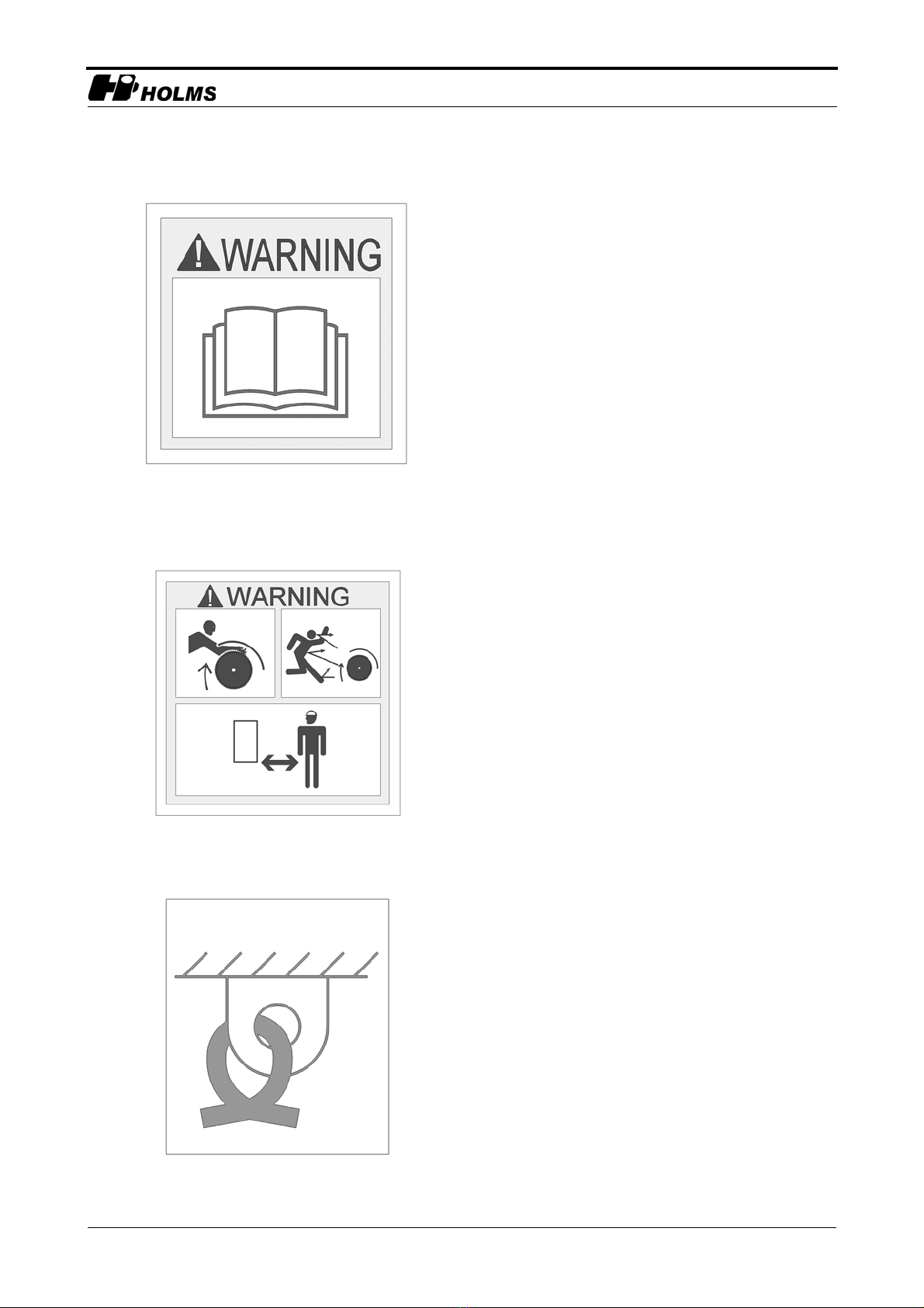
READ THIS DOCUMENT CAREFULLY BEFORE USING THE EQUIPMENT.
Important safety aspects to take into consideration
• Make sure that the tractor/loader can carry the equivalent tool type and weight.
• Make sure that for this sweeper the carrier has a suitable hydraulic oil flow.
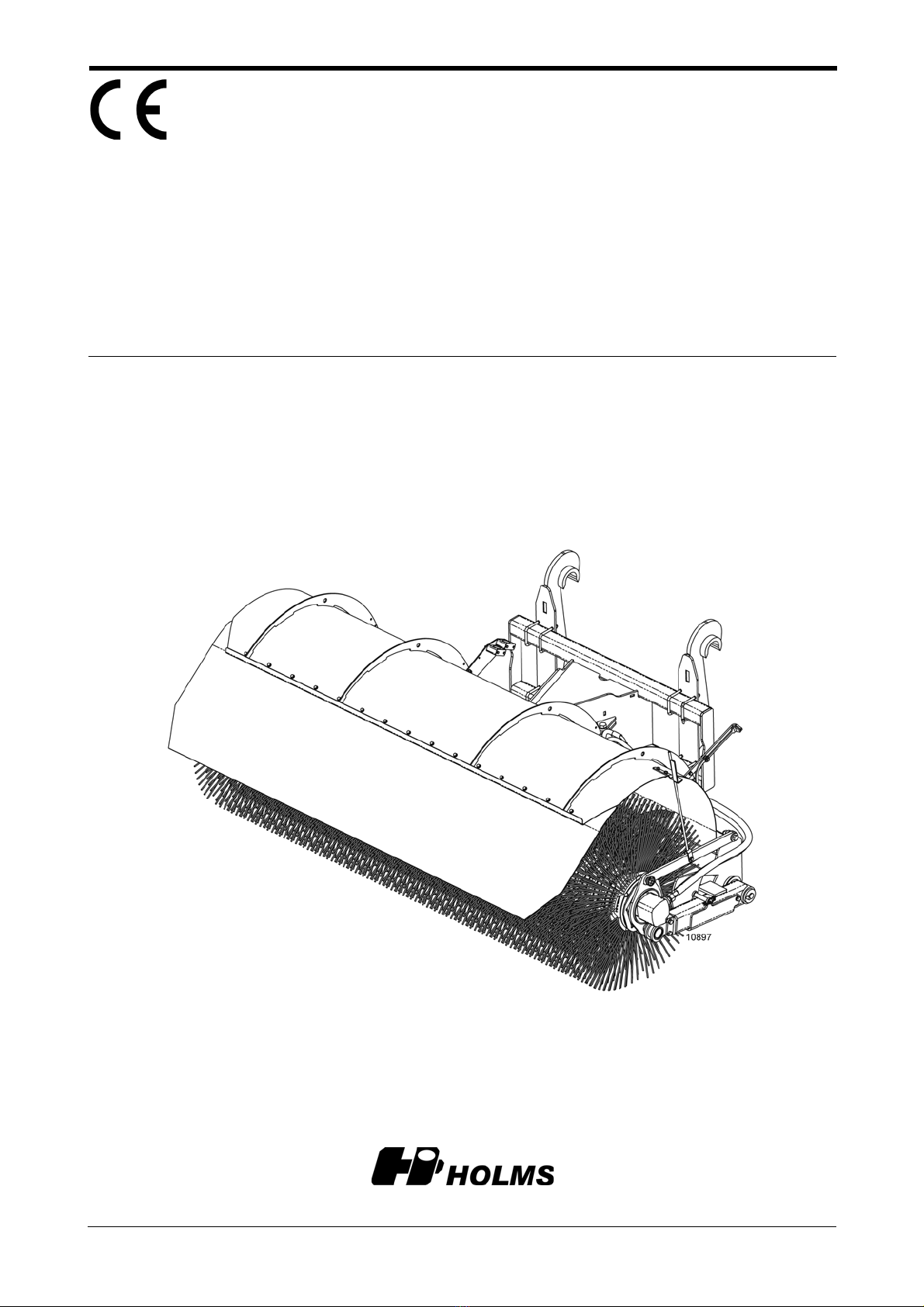
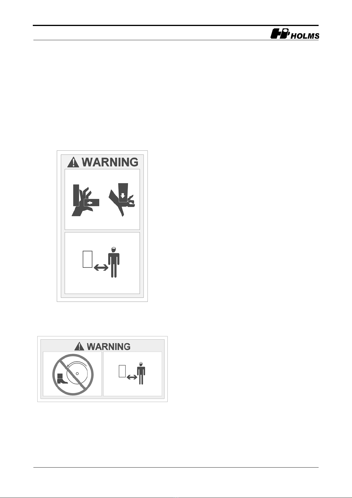
• Make sure that no unauthorised persons are loitering in the machine’s working area when working
with the machine or carrying out servicing.
• Always use the dust covers for the quick-couplings when the machine is disconnected, to prevent
dirt getting into the hydraulic system.
Safety
This instruction manual is intended to be used as a guide for the correct use and maintenance of the
machine. Study the manual carefully before starting and operating the machine and before any
preventive maintenance is carried out. A lot of time has been spent on designing and manufacturing
the machine so that it will be as efficient and safe as possible, all of which will be of little use if you
do not read, understand and follow the instructions. Familiarise yourself with the product and all the
instructions, and keep the instruction manual safe so that it is always readily at hand when using the
machine.
NB
THIS MANUAL HAS BEEN PREPARED FOR ALL OUR MARKETS AND MAY THEREFORE INCLUDE DIFFERENT
EQUIPMENT FOR SPECIFIC MARKETS. PLEASE IGNORE THE SECTIONS THAT DO NOT APPLY TO YOUR
MACHINE.
We continuously strive to improve our products and therefore reserve the right to change design
specifications and implement improvements whenever we consider this necessary; however, such
improvements will not be made to products that have already been delivered or put to work. We also
reserve the right to change data and equipment without prior notice, as well as instructions for
maintenance and other service procedures.
The operator is responsible for ensuring that:
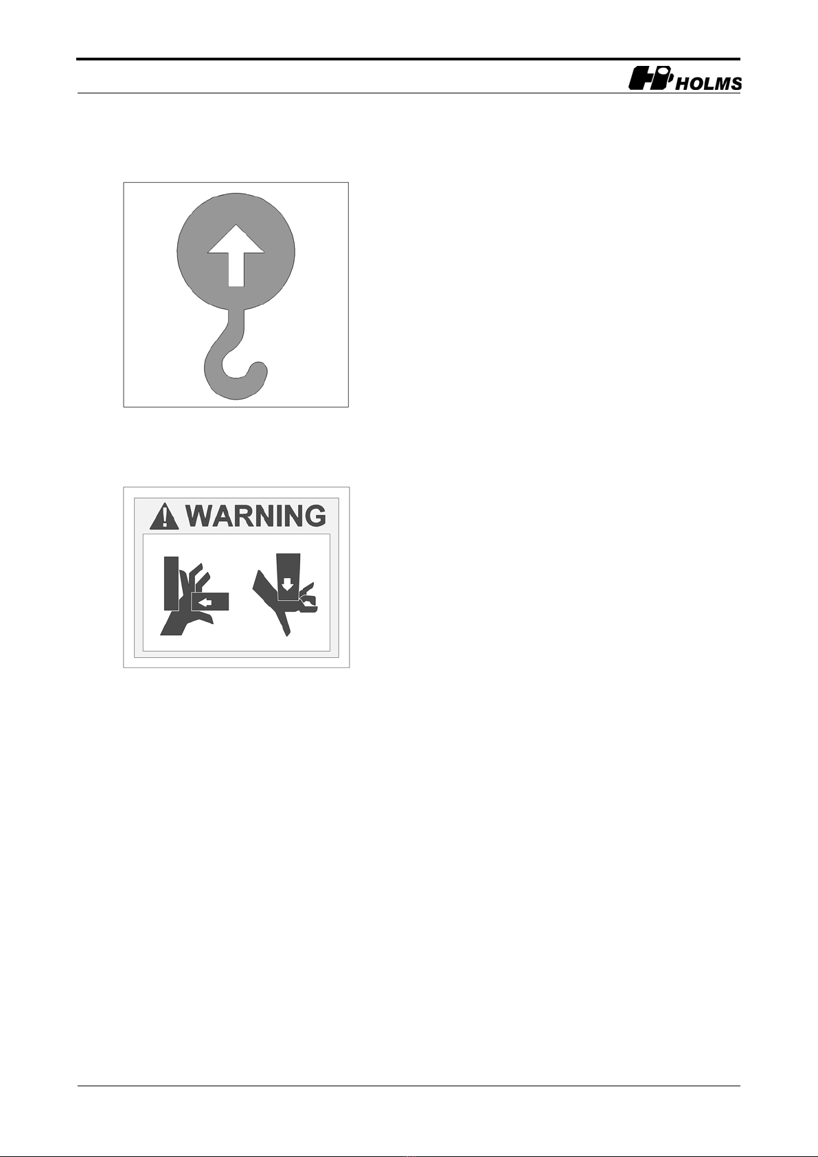
Please pay special attention to the warning symbols.
Make sure you tighten the screw joint reinforcement.
The machine is not used or handled incorrectly.
That any warning labels on the machine are legible.
Unauthorised persons do not use the machine or remain within the machine’s
working area during its operation or maintenance.

Holms SP
8© HOLMS INDUSTRI AB, ALL RIGHTS RESERVED 140214.
NB
WESTRONGLY ADVISE AGAINST ANY MODIFICATIONS, CHANGES OR CONVERSIONS THAT HAVE NOT BEEN
APPROVED BY HOLMS.WEALSO WARN AGAINSTUSING SPARE PARTS THAT HAVE NOT BEEN APPROVED BY
HOLMS.DAMAGE OR FAULTS THAT COULD HAVE BEEN CAUSED BY NON-APPROVED SPARE PARTS OR NON-
APPROVED MODIFICATIONS ARE NOT COVERED BY HOLMS’ LIMITED WARRANTY – SEE APPLICABLE
WARRANTY CONDITIONS. HOLMS WILL NOT PROVIDE COMPENSATION FOR ANY PERSONAL INJURY OR
MATERIAL DAMAGE RESULTING FROM THE USE OF NON-APPROVED SPARE PARTS OR MODIFICATIONS.
When ordering spare parts, or otherwise contacting Holms or your local dealer, always specify the
machine type and its serial number. (Specified on the product’s machine plate.)
The carrier is suitable for use with the machine (hydraulic oil flow, stability,
etc.).

Holms SP
© HOLMS INDUSTRI AB, ALL RIGHTS RESERVED 140214. 9
Product data
SP 2.5 SP 3.0 SP 3.5
Working width (m) 2.5 3.0 3.5
Max. width (m) 2.8 3.3 3.8
Max. height without sprinkler (m) 1.2 1.2 1.2
Max. height with sprinkler (m) 1.3 1.3 1.3
Working width, fully turned 30° (m) 2.2 2.6 3.0
Weight with standard plastic brush (kg) 600 680 760
Weight with sprinkler, empty tank (kg) 60 60 -
Centre of gravity, dimension A standard equipment (mm) 740 770 800
Centre of gravity, dimension B standard equipment (mm) 210 220 230
Centre of gravity, dimension A with sprinkler, empty (mm) 730 760 -
Centre of gravity, dimension B with sprinkler, empty (mm) 250 260 -
Centre of gravity, dimension A with sprinkler, full (mm) 720 730 -
Centre of gravity, dimension B with sprinkler, full (mm) 410 410 -
Max. oil flow (litres/min) 350 350 350
A
B
1.Centre of gravity

Holms SP
10 © HOLMS INDUSTRI AB, ALL RIGHTS RESERVED 140214.
Machine identification plate
Eachtoolhasamachineidentificationplatelocatedasper
figure 2.
The machine identification plate shows the following
information:
• Machine type
• Serial No.
• Year of manufacture
• Weight
• Code of the person who assembled the tool
(Assembler)
• Code of the person who checked the tool on delivery
(Checked).
2.Machine identification plate

Holms SP
© HOLMS INDUSTRI AB, ALL RIGHTS RESERVED 140214. 11
Product description
Holms SP is an extremely robust sweeper roller designed
for front-mounting on loaders. The area of application is
sweeping of “heavy” rubbish such as waste: minerals,
sawmill waste, etc. The sweeper roller is driven by two
direct-acting hydraulic motors housed inside the brush
core and requires an oil flow of 80-350 litres per minute.
Standard model
Holms SP consists of a roller brush suspended from a
central section that can be angled. Splash guard comes as
standard. The machine is supplied with screw-mounted
attachment hooks. The suspension of the sweeper roller
ensures a constant and uniformly distributed brush
pressure to the ground.
Optional extras
• Sprinkler system consisting of water tank (240 litres),
electric pump and spraying bar.
• Hydraulic angling
• Electrohydraulic angling
3.Holms SP with sprinkler system

Holms SP
12 © HOLMS INDUSTRI AB, ALL RIGHTS RESERVED 140214.
Transport and storage
Transporting the machine
When loading and unloading, lift the machine using the
marked lifting eyes. Please note that these differ
depending on whether or not your machine is equipped
with a sprinkler system. See figure 4 and figure 5.
Storage
Park on supports to avoid damage to the brush.
When storing, remember to drain the sprinkler system.
Make sure that the machine is lubricated; there are five
lubrication points. See figure 10 on page 16.
Use approved lifting devices only.
When transporting the machine, use the marked
loops to secure the machine during transit.
4.Lifting points Holms SP without sprinkler
system
5.Lifting points Holms SP with sprinkler
system

Holms SP
© HOLMS INDUSTRI AB, ALL RIGHTS RESERVED 140214. 13
Operating instructions
NB! TOPREVENT THE SWEEPER’SHYDRAULIC MOTORS
BEING DAMAGED BY PRESSURE PEAKS, THE LOADER’S
ENGINE REVS MUST BE REDUCED BEFORE THE SWEEPER IS
TURNED OFF.
Connection to carrier
1. Connect the sweeper roller to the loader’s machine
attachment. See the instruction manual for the loader
in question.
2. Connect the drive hoses to the third hydraulic
function outlet or to the hydraulic motor circuit on the
loader.
Settings
Adjustment of the sweeper roller for height and tilt
1. Lift the machine up off the ground.
2. Lift and lock the supports in the operating position
(see figure 6).
3. Slowly lower the sweeper roller so that the height
indicator’s yellow markings line up (see figure 7).
4. Tilt until the machine’s yellow-marked tilt indicators
are lined up (see figure 7). Readjust the height where
appropriate.
Adjusting ground pressure
The ground pressure can be adjusted to suit different con-
ditions. Adjustments are made by stretching or loosening
the springs that hold the lower slewing brackets. The
ground pressure on the left side of the sweeper roller
(viewed from the carrier) is increased by turning the
spring tensioner clockwise, and reduced by turning it an-
ti-clockwise (see figure 8). On the right side of the sweep-
er roller, the spring tensioner is turned anti-clockwise to
increase the ground pressure and clockwise to reduce it.
NB! Tighten or loosen both sides equally when making
an adjustment.
Check that the machine is secured to the carrier.
Check before connecting that the hydraulic
couplings are properly clean, in order to avoid
operating problems due to dirty oil.
6.Supports in operating position
Height indicator
Tilt indicator
7.Adjustment of height and tilt
8.Adjusting ground pressure (left side of
sweeper roller viewed from carrier)
higher ground
pressure
lower ground
pressure
locking nut
spring tensioner

Holms SP
14 © HOLMS INDUSTRI AB, ALL RIGHTS RESERVED 140214.
Adjusting the ground pressure
1. Lift the sweeper roller. Open up and secure the
support in the operating position.
2. Lower the sweeper roller to ground level (or onto a
trestle), so that the sweeper roller’s lower slewing
brackets are in their top position and the springs are
minimally loaded.
3. See figure 8 on page 13 – fit a ½" ratchet handle into
the square hole in the centre of the spring tensioner.
4. Loosen the nut on the locking screw. Hold the ratchet
handle in place while you remove the locking screw.
Turn the ratchet handle clockwise or anti-clockwise,
depending on the desired adjustment. Adjust the
ground pressure no more than 165°(corresponds to a
maximum of 3 holes in the outer tension plate and one
step on the inner tension plate).
5. Refit the locking screw and locking nut. Check that
the nut is securely tightened.
Operation
Normally the height and tilt indicators must be lined up
during operation. If you want to increase or reduce the
pressure on one side with the roller in an angled position,
this can be done by using the tilt function. This is useful
when you are sweeping pavements, for example, and
have two wheels on the pavement and two on the road, or
when the roller brush is unevenly worn. Tilting the
sweeper roller forwards increases the ground pressure on
the side of the sweeper roller that is angled away from the
carrier.
Do not use the carrier’s lifting or tilt function to
adjust the ground pressure.
Always turn the sweeper roller off properly before
making any adjustments.
Be careful. There is a risk of crushing when
adjusting ground pressure!

Holms SP
© HOLMS INDUSTRI AB, ALL RIGHTS RESERVED 140214. 15
Electrohydraulic angling
In order to be able to angle the roller, the roller brush
must be in contact with the ground.
Disconnection from carrier
1. Release the machine attachment's lock pins before
lowering the sweeper roller to the ground in order to
prevent damage to the counterbalancing system.
2. Close down and lock the supports in the parking
position (see figure 9).
3. Lower the sweeper roller to the ground.
4. Release the hydraulic hoses from the carrier, fit the
plastic covers over the quick-couplings to protect
against dirt, and disconnect the electrical connection
to the water pump (if the sweeper roller is equipped
with a sprinkler system). NB! The brush becomes
deformed if the roller is not parked on the supports.
Sprinkler system (optional extra)
Sweeper rollers with a sprinkler system are equipped
with two water filters toprevent dirt getting in. One filter
sits in the tank filling hole, whilst the other filter is
located on the pump connection. Check the filters at
regular intervals and rinse clean as required. The filters
must always be in place to avoid damage to the pump or
blockages in the spray nozzles.
The pump must not be run for long periods when dry,
i.e. once the water has been used up the pump must be
switched off.
When there is a riskof freezing, the tank, pumpand hoses
must be emptied of water. When the tank is empty, run
the pump for a further 30 seconds or so to ensure that the
pump is also emptied. The easiest way to empty the tank
is to release the hose connections to the tank.
9.Supports in parking position

Holms SP
16 © HOLMS INDUSTRI AB, ALL RIGHTS RESERVED 140214.
Service and maintenance
After operation
Wash the sweeper roller. This prolongs its service life
and makes it easier to detect any leakage or other faults.
Inspect the machine and check that the hoses, brush
guards, springs and machine body are not damaged.
Check also for any oil leakage.
Lubrication
When replacing the brush, lubricate all lubricating
nipples. Clean the nipple and lubricate until grease
appears. See figure 10.
Replacement of brush
It is easiest to replace the brush if the roller brush is
attached to the carrier. Before starting to replace the
brush, lower the roller brush to the ground (parking
supports must be in operating position).
Removing the roller brush
1. Start by removing the moving parts of the height
indicator.
2. Loosen the upper slewing bracket by pulling the pin
out. The roller brush will now move forwards/
downwards.
3. Remove the lower slewing bracket by loosening the
two screws (see figure 11). NB! Requires
considerable force.
4. Unfold the roller brush from the bar tube and remove
the drive unit from the brush core.
5. Remove the entire roller brush from the carrier
housing on the opposite side.
Replacement of brush
1. Loosen the screws on the clamping rings at both ends
of the roller brush and remove them (see figure 12).
2. Insert shackles into both holes at one end of the brush
core and secure a lifting loop in the shackles.
Risk of crushing! The lower slewing bracket is
heavily spring-loaded and flies up unless you hold
it down firmly.
10.Lubricating nipples
11.Screws on lower slewing bracket
12.Clamping rings

Holms SP
© HOLMS INDUSTRI AB, ALL RIGHTS RESERVED 140214. 17
3. Lift the roller brush up on its end using a traverse
hoist or similar.
4. Lift the roller approx. 25 cm off the floor and remove
the brush rings and spacer rings. Then lower the end
to the ground.
5. Check the core for damage.
6. Fit a clamping ring to one end of the brush core
according to figure 13.
7. Lift up the brush core with the clamping ring
downwards.
8. For replacement of brush rings and spacer rings,
see figure 14 and figure 15.
9. Please note that the brush rings should be fitted with
the “spacer” positioned alternately on the brush core
(see figure 16).
10.In order to fill out the brush core towards the end, you
may need to remove one spacer ring and fit double
brush rings.
11.Once the brush core is filled with brushes, screw the
second clamping ring securely in place.
Fitting the roller brush
1. Position the roller brush under the sweeper roller and
lower the sweeper roller.
2. Push the roller brush onto the fixed end carrier
housing.
3. Introduce the removed drive unit into the brush core
and lay the roller brush in the correct position in
relation to the sweeper roller.
4. Fit the lower and upper slewing bracket, and then
screw the height indicator back on.
Risk of crushing!
13.Fitting clamping ring
14.The brush ring pin in the
groove on the brush core
15.Spacer ring
16.Placement of the brush
rings’ pins

Holms SP
18 © HOLMS INDUSTRI AB, ALL RIGHTS RESERVED 140214.
angling
electrohydraulic 11
hydraulic 11
area of application 11
attachment hook 11
bar tube 16
brush
replacement 16
brush pressure 11
carrier housing 16, 17
centre of gravity 9
changes 8
clamping ring 17
clamping rings 16
connection 13
conversions 8
counterbalancing system 15
design modifications 7
disconnection 15
electrohydraulic angling 11
fitting
roller brush 17
ground pressure
setting 13, 14
height 9
height indicator 13, 14
hydraulic angling 11
hydraulic oil flow 7
lifting devices 6
lifting eyes 12
loading 12
lubricating nipples 16
lubrication 16
lubrication points 12
machine attachment 13
machine plate 8, 10
maintenance 16
modifications 8
oil flow 9, 11
product data 4, 9
replacement
brush 16
replacing the brush 16
risk of crushing 14
risk of freezing 15
service 16
service life 16
setting
ground pressure 13, 14
slewing bracket 16
spacer ring 17
spare parts 8
splash guard 11
sprinkler system 11, 12
standard model 11
storage 12
support 13
technical data 4, 9
tilt indicator 13, 14
transport 12
transportation 12
unloading 12
warning labels 7
clean/replace 4
warning symbols 7
water filters 15
water tank 11
weight 9
width 9
working width 9
Index
Table of contents
Other HOLMS Tractor Accessories manuals
Popular Tractor Accessories manuals by other brands

Toro
Toro 04651 Operator's manual

Classic Accessories
Classic Accessories 73967 Instructions & Care

New Holland
New Holland 717173046 Operator's manual

Grouser Products
Grouser Products AG240 Owner's manual & parts book

Maschio
Maschio WEEKEND WARRIOR 6042 Use and maintenance

Grouser Products
Grouser Products 450 Owner's manual & parts book