Gebruder Heyl Analysentechnik Testomat 2000 DUO User manual

1
Testomat 2000® DUO
Online analysis instrument for
water hardness, carbonate hard-
ness, p-value or minus m-value
Operating Instructions

Contents
2
Contents
Contents...............................................................................................2
Important safety information .............................................................4
Intended use .........................................................................................4
Qualification of the staff ........................................................................4
Warning notices in these instructions ...................................................5
Further documents................................................................................5
Pay particular attention to..................................................................5
General instructions..............................................................................5
Installation.............................................................................................6
Operation ..............................................................................................6
Cleaning................................................................................................6
De-installation .......................................................................................6
Disposal ................................................................................................6
Scope of delivery ................................................................................7
Performance specifications...............................................................7
Indicators for Testomat 2000® DUO instruments..................................8
Application instructions.....................................................................9
Installation.........................................................................................10
Operating Testomat 2000®DUO in the pressure range 0.3 to 1 bar..10
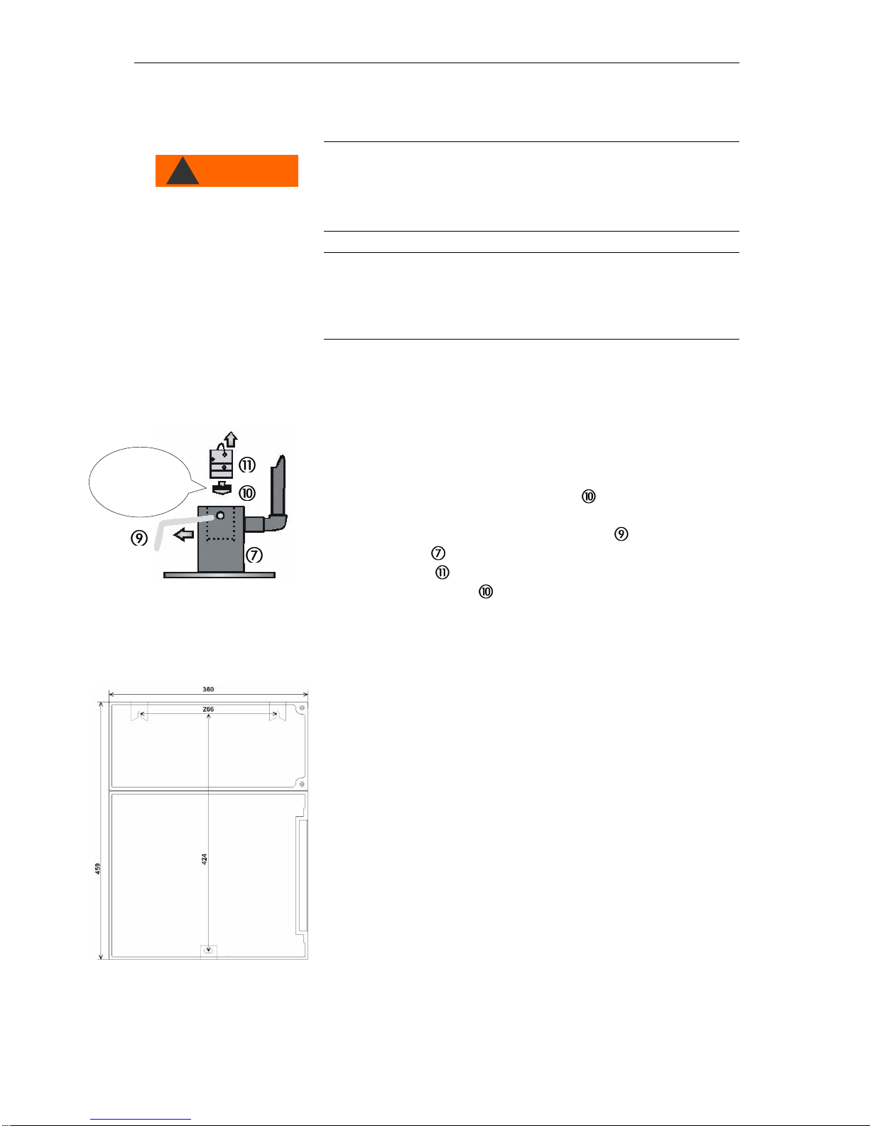
Installing Testomat 2000® DUO ..........................................................10
Connecting the water inlet and outlet .................................................11
Water inlet...........................................................................................11
Water outlet.........................................................................................11
Connecting the power supply and devices .........................................12
Block diagram Testomat 2000®DUO ................................................12
Internal design Testomat 2000®DUO.................................................13
Connecting the mains voltage.............................................................14
Connecting the plant components ......................................................15
Connecting the inputs and outputs .....................................................16
Commissioning.................................................................................17
Inserting the indicator bottle................................................................17
Extracting the indicator .......................................................................17
Opening the water inlet.......................................................................17
Instrument settings and data input......................................................18
Functions of the operating and display elements.........................18
Switching Testomat 2000® DUO on/off...............................................18
Display functions.................................................................................19
Operating elements and function keys ...............................................20
Operating system................................................................................21
Password protection and basic program.......................................22
Entering basic program data...............................................................22
Selecting the indicator and the bottle size ..........................................22
Selecting the operating mode.............................................................23
Selecting the display unit(s)................................................................24
Measuring point or parameter selection .............................................24
Entering further basic program data ..............................................25
Internal flushing...................................................................................25
External flushing .................................................................................25
Interval pause .....................................................................................26

Contents
3
Limit value monitoring.........................................................................26
Hysteresis ...........................................................................................27
Switch functions of the limit value outputs LV1 and LV2....................28
Switch function 0, duration..................................................................28
Switch function 1, impulse ..................................................................28
Switch function 2, interval...................................................................28
Function IN1........................................................................................28
Water meter ........................................................................................28
Alarm / Message.................................................................................29
Function AUX......................................................................................29
Service II.............................................................................................30
Reset operating time...........................................................................30
Maintenance interval...........................................................................30
Description of the signal inputs/outputs........................................31
Interfaces (optional) ............................................................................33
Monitoring a measuring point..............................................................33
Monitoring of two measuring points....................................................33
Calculating the output currents...........................................................34
Serial interface RS232........................................................................35
Description of the relay outputs......................................................35
Flushing (external flush valve)............................................................35
LV1 and LV2 limit value outputs .........................................................35
Measuring points 1 or 2 (measuring point switch-over)......................36
Alarm (fault message output)..............................................................37
Maintenance (output for maintenance message) ...............................38
Information menu "i" ........................................................................39
Program menu "M" ...........................................................................40
Structure of the basic program............................................................42
Error messages / Troubleshooting .................................................43
Further information..............................................................................44
Maintenance ......................................................................................45
Description of maintenance work........................................................45
Service instructions.............................................................................46
Testomat 2000®spare parts and accessories................................47
Accessories.........................................................................................48
Technical data...................................................................................49

Important safety information
4
Important safety information
Please read these operating instructions carefully and completely
prior to working with the instrument.
Ensure that these operating instructions are always available for all
users.
These operating instructions must always be passed on to the new
owner should Testomat 2000®DUO change hands.
Always adhere to hazard warnings and safety tips when using
reagents, chemicals and cleaning agents. Please adhere to the
respective safety data sheet! Download the safety data sheets for
the supplied reagents at http://www.heyl.de .
Intended use
Testomat 2000®DUO is used for the automatic determination and
monitoring of residual total hardness (water hardness), residual car-
bonate hardness, as well as the minus m-value and the p-value in
water. The measurement parameters and the respective measuring
range are determined by the indicator selection and according to the
user programming.
Always adhere to the performance limits stated in the section enti-
tled “Technical data”.
Always observe the application areas/application limits of the indi-
cators and the requirements of the medium being measured.
To ensure correct and intended usage, always read and understand
these instructions, especially the section entitled “Important safety
information”, prior to use.
The instrument is not used as intended if
it is used in areas not specified in these instructions,
it is used in areas which do not correspond to the ones described
in these instructions.
Qualification of the staff
Assembly and commissioning require fundamental electrical and
process engineering knowledge as well as knowledge of the respec-
tive technical terms. Assembly and commissioning should therefore
only be carried out by a specialist or by an authorised individual su-
pervised by a specialist.
A specialist is someone who due to his/her technical training, know-
how and experience as well as knowledge of relevant regulations can
assess assigned tasks, recognise potential hazards and ensure ap-
propriate safety measures. A specialist should always adhere to the
relevant technical regulations.

Pay particular attention to
5
Warning notices in these instructions
The warning notices in these instructions warn the user about poten-
tial dangers to individuals and property resulting from incorrect han-
dling of the instrument. The warning notices are structured as follows:
Description of the type or source of danger
Description of the consequences resulting from non-observance
Preventive measures. Always adhere to these preventive
measures.
“DANGER” indicates an immediate hazardous situation which, if not
avoided, will result in death or serious injury.
“WARNING” indicates a potentially hazardous situation which, if not
avoided, could result in death or serious injury.
“CAUTION” indicates a potentially hazardous situation which, if not
avoided, could result in minor or moderate injuries or property dam-
age.
“NOTE” indicates important information. If this information is not
observed, it may result in an undesirable result or state.
Further documents
Testomat 2000®DUO is a plant component. Therefore, always ob-
serve the maintenance manual of Testomat 2000® / Testomat 2000
ECO®and the documentation of the plant manufacturer.
Pay particular attention to
General instructions
Please adhere to health and safety regulations, electrical equip-
ment safety regulations, and environmental protection regulations
valid in the country of use and at the installation site.
Adhere to national and local regulations during installation and
commissioning.
Always protect the instrument against moisture and humidity. It
should never come into contact with condensation or splash water.
Do not carry out any changes or actions at the instrument which are
not described in these instructions;
failure to adhere to these in-
structions will negatively affect any warranty claims that you make
thereafter.
SIGNAL WORD!
DANGER
!
WARNING
!
CAUTION
!
NOTE
WARNING
!

Pay particular attention to
6
Installation
Always completely disconnect the relevant plant part before in-
stalling the instrument or connecting/disconnecting it to/from the
power supply. Secure the plant against reconnection.
Only connect the instrument to the mains voltage specified on the
rating plate.
Always observe technical data and ambient parameters.
Testomat 2000®DUO requires an interference free and stable
power supply. If necessary, use a mains filter to protect Testomat
2000®DUO against interference voltages caused, e.g., by solenoid
valves or large motors. Never lay connecting cables parallel to
power cables.
Operation
Ensure that the maximum electrical load capacity of the relay out-
puts is never exceeded.
Immediately switch off Testomat 2000®DUO and contact service
staff if malfunctioning occurs. The warranty will be void if you tam-
per with or attempt to repair Testomat 2000®DUO. Repairs must
be carried out by authorised service staff.
Cleaning
Only use a dry, lint-free cloth for cleaning.
De-installation
Prior to de-installing a defective instrument, always write down a
description of the error (failure effect). It is only possible to repair a
defective instrument (irrespective of the warranty period) if it has
been de-installed and returned to us with a description of the error.
Disposal
Dispose of the instrument in accordance with national regulations.
WARNING
!
NOTE

Scope of delivery
7
Scope of delivery
1 Testomat 2000® DUO
1 Plastic bag with two screw caps with a hole and an insert for the
screw caps of the indicator bottles
1 operating instructions
Performance specifications
Testomat 2000®DUO is used for the automatic determination and
monitoring of residual total hardness (water hardness), residual car-
bonate hardness, as well as the minus m-value and the p-value in
water. The instrument can be used to alternately measure two pa-
rameters at one measuring point or two measuring points with differ-
ent (or the same) parameters. The measurement parameters and the
respective measuring ranges are determined by the indicator selec-
tions and according to the user programming.
Simple, menu-driven operating and programming via a plain
text display
Determinable measuring of residual hardness, total hard-
ness, carbonate hardness, minus m-value, p-value via indica-
tor selection
Freely selectable hardness unit in °dH, °f, ppm CaCO3or
mmol/l
High measuring accuracy provided by a precise piston-
dosing pump
Analysis initiation:
- Automatic interval operation
(interval pause can be set from 0-99 minutes)
- External control
- Quantity dependent via impulse water meter
Two independent limit values with hysteresis (1, 2 or 3 bad
analyses) and settable switch functions
Monitoring of two measuring points (change-over via external
solenoid valves)
Internal error documentation
Programmable service address
Programmable maintenance interval for a maintenance re-
quest
Extended operating periods due to 500 ml indicator storage
bottle
optional:
Interface card (0/4-20 mA or 0/2-10 V)
Interface RS 232 (for a protocol printer)

Performance specifications
8
Indicators for Testomat 2000® DUO instru-
ments
Parameter/Indicator type
Water hardness
TH 2005
TH 2025
TH 2100
TH 2250
Unit
°dH
(resolution)
0.05 –0.50
(0.01)
0.25 –2.50
(0.05)
1.0 –10.0
(0.2)
2.5 –25.0
(0.5)
°f
(resolution)
0.09 –0.89
(0.02)
0.45 –4.48
(0.1)
1.8 –17.9
(0.4)
4.5 –44.8
(1.0)
ppm
CaCO3
(resolution)
0.89 –8.93
(0.2)
4.5 –44.8
(0.9)
18 - 179
(3.8)
45 - 448
(10)
mmol/l
(resolution)
0.01 –0.09
(0.002)
0.04 –0.45
(0.01)
0.18 –1.79
(0.04)
0.45 –4.48
(0.1)
Parameter
/Indicator
type
Carbonate
hardness
minus m-
value
p-value
p-value
TC 2050
TC 2100
TM 2005
TP 2010
TP 2100
Unit
°dH
(resolution)
0.5 –5.0
(0.5)
1.0 –20.0
(1.0)
-
-
-
°f
(resolution)
0.90 –8.96
(0.9)
1.8 –35.8
(1.79)
-
-
-
ppm
CaCO3
(resolution)
8.9 –89.5
(8.9)
18 - 358
(18)
-
-
-
mmol/l
(resolution)
0.18 –1.79
(0.18)
0.36 –7.16
(0.36)
0.05 –0.50
(0.01)
0.1 –1.5
(0.1)
1 - 15
(1)
Display, if measuring value is outside of range (for example TH2005):
At falling below: < 0,05°dH
At exceeding: > 0,50°dH

Application instructions
9
Application instructions
Wait at least 5 seconds before switching the instrument on and
then off again at the main switch.
In order for Testomat 2000®DUO to operate reliably, use Heyl
Testomat 2000®indicators in the pH-range 4 –10.5!
With Testomat®instruments for water hardness monitoring, larger
quantities of heavy metal ions in the softened water might influ-
ence the colour reaction, especially iron above 0.5 mg/I, copper
above 0.1 mg/I and aluminium above 0.1 mg/l (brownish-red colour
display).
If the measuring water contains more than 20 mg/I CO2(carbonic
acid), incorrect evaluations cannot be excluded.
The concentration of influencing contents can be determined by
using our colourimetric TESTOVAL®test kit.
Careful handling of the instrument increases both its operational
reliability and service life! Therefore, carry out a visual inspection
at regular intervals as described below:
- Has the use-by date of the indicator expired?
- Are the hose connections of the dosing pump free of leaks?
- Is there air inside the dosing hoses?
- Are all the water connections free of leaks?
- Are the doors of the instrument closed properly?
- Is the instrument heavily soiled?
- Are the measuring chamber and the drain duct/drain hose
clean?
Trouble-free operation is only possible when maintenance is car-
ried out on a regular basis! For more information, please refer to
the section entitled “Maintenance” and the "Maintenance manual
of Testomat 2000® / Testomat 2000 ECO®"
If problems occur, please refer to the section entitled "Error mes-
sages/Troubleshooting”.

Installation
10
Installation
Risks resulting from incorrect installation!
Install Testomat 2000® DUO at a location where it is protected
against dripping or splash water, dust and aggressive substances
–e. g. in a switch cabinet or on a suitable wall.
Information for trouble-free operation
Install Testomat 2000® DUO vertically and without mechanical
stress.
Install Testomat 2000® DUO at a vibration-free site.
Operating Testomat 2000®DUO in the pres-
sure range 0.3 to 1 bar
Prior to installation, please check whether lower operating pressure is
required. The instrument is factory set for the operating range 1 to 8
bar. Remove the flow controller valve body to operate the instru-
ment in the operating range 0.3 to 1 bar (e.g. when using an aerator
type R). This involves removing the retaining pin from the control-
ler / filter receiver . Subsequently use the metal bracket to remove
the controller plug from the borehole. Subsequently remove the
flow controller valve body and reinsert the controller plug and the
retaining pin.
Installing Testomat 2000® DUO
Select an installation site where the water inlet hose can be kept as
short as possible (max. 5 m).
Please leave sufficient space on the left-hand side of the instru-
ment to open the door.
Drill the mounting holes as shown in the drawing on the left.
Use three screws to attach the instrument at a suitable position in
the switch cabinet or on a wall.
NOTE
Remove for
pressure
range 0.3 to 1
bar
WARNING
!

Installation
11
Connecting the water inlet and outlet
Information for trouble-free operation
The water pressure must be between 0.3 bar and 8 bar
Avoid strong pressure fluctuations
The measuring water temperature must be between 10 °C and
40 °C
For temperatures above 40 °C, the KCN type cooler should be
installed in the branch line of Testomat 2000® DUO.
Water inlet
The measuring water is taken from the main water line of the water
treatment plant and fed to the inlet connection of Testomat 2000®
DUO. The instrument is equipped with a plug connector for plastic
hoses 6/4 x 1 (external diameter 6 mm/ internal diameter 4 mm, wall
thickness 1 mm) as standard.
Install the connection for the branch line of Testomat 2000® DUO
directly at the main water line directly after the water treatment
plant
It is important that the branch line connection is laid vertically up-
wards in order to prevent dirt particles from entering the instru-
ment from the main water line
Install a manually operated shut-off valve Testomat 2000®DUO
Use an opaque plastic hose 6/4 x 1 (max. length 5 m) for the water
inlet
Flush the inlet to remove any dirt particles
When operating within a pressure range of 0.3 to 1 bar or with a sup-
ply via a booster pump, please remove the valve body from the con-
troller and the filter housing. The pump should have a feeding capaci-
ty of between 25 and 35 litres/hour and be resistant to the medium
being measured.
When using a cooler
The hot water can cause burns and damage wetted parts of
Testomat 2000® DUO.
Water outlet
The feed water flows through the measuring chamber to the drain via
the outlet hose.
Connect the outlet connection of Testomat 2000®DUO to an
opaque outlet hose (internal diameter 14 mm).
Lay this hose without backwater development and any syphoning
effect, e.g. via an open funnel, to the drain
NOTE
NO !!
"Sagging"
causes back-
water!
CAUTION
!

Installation
12
Connecting the power supply and devices
Risk of electric shocks during installation!
If the power supply is not disconnected prior to installation, it may
result in personal injuries, destruction of the product or damage to
plant parts.
Always disconnect the relevant plant parts before installing Tes-
tomat 2000® DUO.
Only use tested cables with sufficient cross-sections for the con-
nections.
Risk of damages caused by electromagnetic fields!
If Testomat 2000® DUO or the connecting cables are installed
parallel to power cables or in close proximity to electromagnetic
fields, the instrument may be damaged or measurements incor-
rect.
Ensure that connecting cables are as short as possible.
Always install connecting cables and power cables separately.
Connect the instrument to the protective earth conductor (for
230/115 VAC).
Protect Testomat 2000® DUO against interference voltages –e.g.
via a mains filter.
Shield the instrument against strong electromagnetic fields.
Block diagram Testomat 2000®DUO
Drawn relay positions: Instrument de-energised
WARNING
!
NOTE

Installation
13
Internal design Testomat 2000®DUO
Terminal strip for inputs Start, Stop, IN1, IN2, and output OUT
Mains switch
Terminal strip for power input and power output
Terminal strip for relay outputs
Dosing pumps
Water connections, inlet and outlet
Flow controller
Measuring chamber

Installation
14
Connecting the mains voltage
Only connect the instrument to the specified mains voltage. Refer to
the rating plate for the appropriate mains voltage. Connect the cables
as follows:
Loosen both fastening screws and open the upper door. The
terminal box is now accessible.
Pierce the required rubber cable glandswith a screwdriver and
insert the cable through the bush into the terminal box (1)
Subsequently pull back the cable until the bush has been turned
over (2)
Connect the power supply to terminals PE,N,L or for 24 V instru-
ments to terminals U,V
Connect the conductor to the terminal block as shown on the left
.
Ensure that the leads are held securely in the terminals
Proceed as shown in figure to loosen the connection.
Terminal
description
Type
Function
Comment
PE
IN
Mains –protective earth
(5x)
Only with mains
115/230 V !
N (U)
L (V)
IN
Mains, N=neutral (U=24V)
Mains, L=live (V=24V)
Mains input
24 V / 115 V / 230 V
n
l
OUT
Neutral, switched (8x)
Live, switched (8x)
Mains for consumers,
max. 4 A
Insert the conductor with
ferrule or the solid conductor
into the round input.
1. Insert a screwdriver
into the square opening
without force in order
to open the terminal.
2. Once the terminal has been
opened, remove the conductor.

Installation
15
Connecting the plant components
Connect the plant components to the output terminals of relays 1
to 19 (e.g. valves)
If the plant components require mains voltage, connect the
switched mains voltage (l) to the common contact of the re-
spective relay (see the connection example for 230 VAC on the
left)
Connect the neutral conductor of the plant component to one of the
terminals (n)
For components with a protective earth conductor connection,
connect it to the PE connection
Ensure that the leads are held securely in the terminals
No.
Terminal
description
Type
Function
Comment
1
2
Flush
OUT
External flush valve
Isolated relay output,
max. 240 VAC, 4 A
3
4
5
LV1
OUT
Limit value output 1 –Normally closed
Limit value output 1 –Normally open
Limit value output 1 –Common
Isolated relay output,
max. 240 VAC, 4 A
6
7
8
GW2
OUT
Limit value output 1 –Normally closed
Limit value output 1 –Normally open
Limit value output 1 –Common
Isolated relay output,
max. 240 VAC, 4 A
9
10
11
Measur-
ing points
1/2
OUT
Measuring point 1 –Normally closed
Measuring point 2 –Normally open
Measuring point switch-over - Common
Isolated relay output,
max. 240 VAC, 4 A
12
13
AUX
OUT
Universal output
Isolated relay output,
max. 240 VAC, 4 A
14
15
16
Alarm
OUT
Fault message output –Normally closed
Fault message output –Normally open
Fault message output –Common
Isolated relay output,
max. 240 VAC, 4 A
17
18
19
Mainte-
nance
OUT
Maintenance message - Normally closed
Maintenance message - Normally open
Maintenance message - Common
Isolated relay output,
max, max. 240 VAC,
4 A
Connection example:
Limit value contact LV 1
switches mains voltage
n
l
3
4
5
e.g.
solenoid
valve
PE

Installation
16
Connecting the inputs and outputs
Testomat 2000® DUO has the following connections for control and
monitoring functions.
Do not connect external voltage to these connections!
Ensure that the leads are held securely in the terminals.
Use the two fastening screws to close the upper door once installa-
tion has been completed.
For more information, please refer to the section entitled "Description
of the signal inputs/outputs".
No.
Terminal
description
Typ
e
Function
Comment
20
21
Start
IN
External analysis start
Common earth for inputs
Only for isolated normally open!
22
23
Stop
IN
External analysis stop
Common earth for inputs
Only for isolated normally
closed/normally open!
24
25
IN1
IN
Universal input 1
Common earth for inputs
Only for isolated normally
closed/normally open!
26
27
IN2
IN
Universal input 2 (water meter)
Common earth for inputs
Only for isolated normally open!
┴
28
29
OUT
OUT
OUT
OUT
OUT
OUT
IN
RS 910: Earth
SK910:
(+)
UK910:
(+)
RS910:
(TxD)
SK910:
(-)
UK910:
(-)
RS232:
(RxD)
RS232 interface for printer
Galvanically separated current
interface 0/4 - 20mA
Galvanically separated voltage
interface 0/2 –10V
RS232 interface for printer
Galvanically separated current
interface 0/4 - 20mA
Galvanically separated voltage
interface 0/2 –10V
RS232 interface for printer

Commissioning
17
Commissioning
In order for Testomat 2000® DUO to operate reliably, only use Heyl
Testomat®
indicators
!
Inserting the indicator bottle
Open the lower housing door by pulling on the right-hand side.
Remove the cap from the indicator bottle
Remove the plastic bag from inside the lower housing door. The
plastic bag contains the screw cap with hole and the insert
for the screw cap.
Connect the parts as shown on the left.
Screw the hose connector of the intake hose hand-tight into
the insert .
Place the insert with the screwed-in intake hose into the indicator
bottle.
Now screw the screw cap with hole hand-tight onto the
indicator bottle.
Extracting the indicator
During operation, the pump (DOSIClip) automatically extracts
the indicator.
To ensure that indicator is available for the initial analyses, the
intake hose and the transport hose must be filled with indica-
tor from the pump up to the measuring chamber.
Press the "manual" key several times until the intake hose
and the transport hose are filled with indicator up to the meas-
uring chamber (always switch on the instrument at the mains
switch first!)
Opening the water inlet
Open the lower housing cover.
Slowly open the manually operated shut-off valve to prevent the
measuring chamber overflowing. The flow regulator requires a few
seconds to function correctly.
Make sure that the water conducting parts are not leaky.
CAUTION
!

Functions of the operating and display elements
18
If water sprays from the vent hole of the measuring chamber
, reduce the amount of inlet water via the manually operated
shut-off valve. It should take 2 to 6 seconds to fill the measuring
chamber!
Instrument settings and data input
Please read the following information before carrying out settings
and entering data for operating the instrument.
Functions of the operating and dis-
play elements
The Testomat 2000® DUO display shows operating statuses and
measured values. The input keys for programming (cursor block) and
the function keys are located underneath the display.
Switching Testomat 2000® DUO on/off
(1) Mains switch
Use this switch to switch the instrument on or off.
(2) Instrument fuse (inside the instrument)
This fuse protects Testomat 2000®DUO and the outputs
against overloads and short circuits.
(1)
(2)

Functions of the operating and display elements
19
Display functions
1 Status of limit value displays (red/green)
The display 1 illuminates red if limit value 1 has been reached or
exceeded. The display 1 illuminates green if the value falls below
the limit value. The same principle applies to limit value 2 and dis-
play 2.
2 Text display (4 lines)
Displays the current analysis result as well as all important status-
es and programming data:
Line 1 = the set indicator types for measuring point 1 (M1:)
and 2 (M2:) are displayed. (P1:/P2:) is displayed for
for a measuring point.
Line 2 = measured value display measuring point (M1) or (P1)
Line 3 = measured value display measuring point (M2) or (P2)
Value falls below the measuring range = "<" e.g. M1: < 0.05 °dH
Value exceeds the measuring range = ">" e.g. M1: > 5.0 °dH
Line 4 = The set limit values LV1 and LV2 are
displayed
3Alarm (red)
Indicates malfunctioning/error message or warning message.
4 Maintenance message (yellow)
Indicates current maintenance requests
5 Status display of the active instrument components (line)
Six displays indicate the current instrument and analysis status
Cancelling error messages/warning messages
Press to acknowledge the message and, if necessary,
eliminate the cause of the fault.
All error and
warning messages
are alternately
shown in line 1 of
the standard
display!
NOTE
Inlet
valve
Analysis
running
Outlet
valve
Dosing
message
Testomat
2000®
only
Analysis stop

Functions of the operating and display elements
20
Programming
keys
(cursor block)
Operating elements and function keys
If you wish to carry out settings or enter data, or if alterations are
necessary, press the "M" key to open the programming mode. Use
this key when in the menu to go to the higher order menu items or to
exit the programming mode. Please note: The basic program is
password protected!
Programming keys (cursor block)
Use the programming keys (cursor block) to navigate in the menu, to
select the desired functions and to enter necessary instrument and
plant specific data. Press the "ENTER" key to select the submenu
item and to confirm and accept the selection or data input.
Function keys
Manually start an analysis via the "Manual" key
Set the instrument to standby mode via the "STANDBY"
key (automatic analyses are not carried out: analysis
stop)
Acknowledge error and warning messages via the
"Horn" key
Open the program menu for user-specific and instrument-
specific settings via the "M" key
Retrieve all instrument information and settings via the
"i" key
Cursor block
(M)enu key
Table of contents
Popular Measuring Instrument manuals by other brands

VoiceCollect
VoiceCollect IR44CF-II user manual

SDI
SDI db checker instructions

domat
domat AERASGARD RCO2-W Operating Instructions, Mounting & Installation

General Dynamics
General Dynamics R2600 Series Operator's manual

HP
HP 412A Operating and service manual

GFS
GFS 242-001 Installation & operating instructions