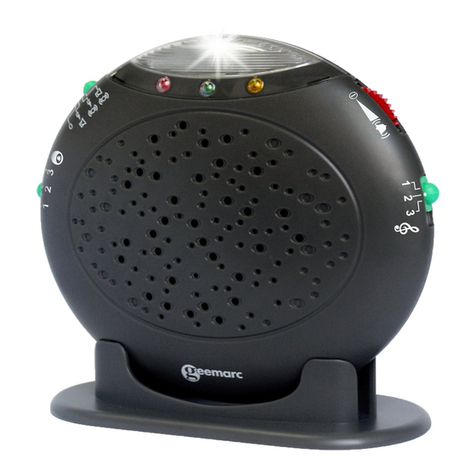
Geemarc clearsound amplicall 20 User manual


2
Description
DESCRIPTION
Red LED
Doorbell tone
control
OrangeLED Strobe flasher
Volume control
Tone control
Speaker
A
larm mode
switch
Low battery indicator
(Green LED)
Table mounting
A
daptor jack
(option)
Wall mounting
screw holes
Shaker jack Modular
j
ack PTT line Modular jack PTT line o
r
for a second Amplicall20
connection
batteries
compartment
(4 X AA)
FRONT
REAR

3
Installation (See drawing)
1 - Insert the 4 x AA battery in the compartment .
2 - Connect the RJ11 to RJ11 cable between the
Amplicall and phone
3 - Connect one end of the telephone line cord to the unit
and the other end to a wall socket.
4 - Connect the adaptor (option).
For serving or replacement, you purchase a
suitable shaker Model no. CLA2 through service
centre or retailer shop
INSTALLATION
Door Bell
button
Door Bell
(Amplicall 1
A
m
p
licall 2\
A
m
p
licall 3
)
A
C adapto
r
230V
UK plug
Option: Shaker
(ref.:SHAKCL_BLK)
Telephone plug

4
Electrical connection : The apparatus is designed to
operate from a 230V 50Hz supply only. (Classified as
«hazardous voltage» according to EN60950 standard).
The apparatus does not incorporate an integral power
on/off switch. To disconnect the power, either switch off
supply at the mains power socket or unplug the AC
adaptor. When installing the apparatus, ensure that the
mains power socket is readily accessible.
Telephone connection : Voltages present on the
telecommunication network are classified TNV-3
(Telecommunication Network Voltage) according to the
EN60950 standard.
Important Safety Instructions
When using your device equipment, basic safety precautions should
always be followed to reduce the risk of fire, electric shock and injury
to persons, including the following:
1. Do not use this product near water, for example, near a bath tub,
wash bowl, kitchen sink or laundry tub, in a wet basement or near a
swimming pool.
2. Avoid using a device (other than a cordless type) during an
electrical storm. There may be a remote risk of electric shock from
lightning.
3. Do not use the device to report a gas leak in the vicinity of the
leak.
4. Use only the power cord and batteries indicated in this manual. Do
not dispose of batteries in a fire. They may explode. Check with local
codes for possible special disposal instructions.
SAVE THESE INSTRUCTIONS!
INSTALLATION
5
Setting up Door bell
1. The Door Bell can be take with the people who need
the assistance.
2. The door bell can be fixed on the wall or door
surround, drill two holes horizontally, 15mm apart,
put the supplied anchor into the two holes, hang the
door bell on to the two anchors and then instert and
tighten screws, and then stick the blank sticker on the
two holes.
3. The door be can be stick onto a door, window using
the supplied strong adhesive tape. Remove the
protective paper from the adhesive tape on the back
of the door bell and stick to the required window.
INSTALLATION

6
Setting UP Indoor unit
Wall Mounting
1. Drill two holes horizontally, 96mm apart, and leave the
screws protruding from the wall by 5mm.
2. Hang the base on to the two screws and pull the base
down to lock it on
Table Mounting
If you want to mount the unit on the table, only put it into
the base cradle, and then place the base cradle on the
table.
Setting The Alarm Mode
Choose which alarm mode you want to by moving the
alarm mode switch to one of the following position:
0 : no alarm
: both strobe flasher and sound alarm activated
: both strobe flasher and shaker (if connected)
activated
: both sound alarm and shaker (if connected)
activated
Volume Control Slide Switch
Use the slider control to adjust the volume of door bell
ring and phone ring or power OFF.
INSTALLATION

7
Tone Control Switch (3 Positions)
Set the tone of the alarm sound.
Door Bell Tone Control
The three position switch allows you to set a different
tone when the door bell rings.
Change the Battery of Indoor unit
The unit requires 4×AA batteries
1. Open the battery door.
2. Insert four AA batteries into the compartment.
3. Snap the battery compartment door back into place.
Note: when the red indicator keep flashes, replace the
batteries. During replacement of the batteries, disconnect
all telephone line cords from the wall modular jacks.
You can add one adaptor in option (contact 01 707-
384438)
Change the Battery of the Door bell
The door bell is supplied with a A23 12V battery. The
Door bell is supplied ready to use, it is not necessary to
open the Door Bell when you first install the Amplicall 20.
To replace the battery, unscrew the door bell from the
wall, unscrew the five screws located on the base and
open the box to get access to the battery compartment.
Replace the battery, replace back and remount.
INSTALLATION

8
Note: Do not use a rechargeable battery. Do not put the
used battery into the household rubbish, pay attention to
battery regulations regarding battery disposal.
The Pairing Procedure:
1. Press and hold the Pairing/Test button until the unit
makes a beep sound, release the Pairing/Test
button, then the 1st LED lights to enter pairing mode.
2. Press and hold the Pairing/Test button again until the
1st LED flashes, then press and hold the remote
button at the same time until the strobe flasher LED
flashes, the unit makes a beep sound to confirm
pairing successfully.
3. If user wants to pair the 2nd or 3rd remote, when the
1st LED lights, press the Pairing/Test button once, the
1st LED goes off and then the 2nd LED lights. User is
able to pair the 2nd remote, repeat the same
procedure for the 3rd remote.
4. Repeat the above, all 3 LEDS flashing together for
the 4th remote pairing.
Un- Register The Pairing:
1. Press and hold the Pairing/Test button for 5 seconds
to enter un-register mode, 3 LEDs flash together.
2. If user wants to un-register the 1st remote, press the
Pairing/Test button once, the 1st LED will be flashing
INSTALLATION

9
(the other 2 LED light), then press and hold the
Pairing/Test button until the 1st LED goes off, beeps to
confirm. The 1st remote is now un-registered.
3. If user wants to keep the 1st remote but un-register
the 2nd or3rd remote, when the 1st LED flashes, press
the Pairing/Test button again, the 2nd LED flashes
(other 2 LED light) to select which remote to be
un-registered.
To check whether the unit works normally, you can press
the pairing/Test button, the unit would sound alarm and
flash.
Operation
Once the indoor unit and the Door Bell have been placed
in the required locations and all required batteries have
been inserted, you are ready to use the device.
To use the device as a door bell, the person who needs
assistance must press the Door Bell button of the door
bell. The indoor unit will be sound alarm and flash
(Depend on the Alarm mode setting).
To use the device a telephone ringer amplier, while a
new call is coming, the indoor unit will be sound alarm
and flash(Depend on the Alarm mode setting)
INSTALLATION

10
Trouble shooting
Symptom Solution
No incoming call, it
rings automatically or
rings continuously; the
shaker vibrates
automatically or
continuously; the
camera LED flashes
automatically.
1) Check if the batteries
contact well.
2) Check if the power
adaptor connects
normally.
3) Turn off the power
switch for 10 minutes
and then turn it on.
When the power supply
works normally, the red
low battery LED flashes
automatically.
1) Check if it is low
battery.
2) Turn off the power
switch for 10 minutes
and then turn it on.
When it is connected to
the power adaptor or
has been installed 4
batteries, however,
when there is an
incoming call, no rings.
1) Check if it is connected
to the power adaptor
correctly;
2) Check if the batteries
are installed right.
3) Check if the volume
switch turns on.
4) Check if it is connected
to the line cord
correctly.
INSTALLATION

11
When it is connected to
the power adaptor or it
has been installed 4
batteries, bell rings
normally, or camera
LED blinks normally,
when there is an
incoming call, the
shaker doesn’t vibrate.
1) Check if it is connected
to the shaker correctly.
2) Check if the shaker
socket has been
damaged.
3) Check if the alarm
mode selection switch
position is correct.
If the AmpliCALL20
does not ring when the
doorbell is pressed
1) Check that the red light
on the doorbell flashes
when it is pressed. If it
does not, change the
battery.
2) Register the doorbell to
the AmpliCALL20 again
3) Make sure the alarm
configuration button is
not on "0"
INSTALLATION

12
- This equipment complies with Part 68 of the FCC rules
and the requirements adopted by the ACTA. On the
bottom of this equipment is a label that contains, among
other information, a product identifier in the format
US:AAAEQ##TXXXX. If requested, this number must be
provided to the telephone company.
- All applicable certification jacks Universal Service Order
Codes (USOC) for the equipment is provided (i.e. RJ11C)
in the package with each piece of approved terminal
equipment.
- A plug and jack used to connect this equipment to the
premises wiring and telephone network must comply with
the applicable FCC Part 68 rules and requirement
adopted by the ACTA. A compliant telephone cord and
modular plug is provided with this product. It is designed
to be connected to a compatible modular jack that is also
compliant. See installation instructions for details.
- The REN is useful to determine the quantity of devices
you may connect to your telephone line and still have all
of those devices ring when your telephone number is
called. In most, but not all areas, the sum of the REN’s of
all devices connected to one line should not exceed five
(5.0). To be certain of the number of devices you may
connect to your line, as determined by the REN, you
should contact your local telephone company to
determine the maximum REN for your calling area.
- If this equipment causes harm to the telephone network,
the telephone company will notify you in advance that
temporary discontinuance of service may be required.
But if advance notice isn’t practical, the telephone
REGULATORY COMPLIANCE

13
company will notify the customer as soon as possible.
Also, you will be advised of your rights to file a complaint
with the FCC if you believe it is necessary.
- The telephone company may make changes in its
facilities, equipment, operation or procedures that could
affect the operation of the equipment. If this happens the
telephone company will provide advance notice in order
for you to make necessary modifications to maintain
uninterrupted service.
- This equipment may not be used on coin service
provided by the telephone company. Connection to party
lines is subject to state tariffs. Warning: Changes or
modifications to this unit not expressly approved by the
party responsible for compliance could void the user’s
authority to operate the equipment.
This device complies with part 15 of the FCC Rules.
Operation is subject to the following two conditions:
(1) This device may not cause harmful interference,
and (2) this device must accept any interference
received, including interference that may cause
undesired operation.
NOTE : This equipment has been tested and found to
comply with the limits for a Class B digital device,
pursuant to Part 15 of the FCC Rules. These limits are
designed to provide reasonable protection against
harmful interference in a residential installation.
This equipment generates, uses and can radiate radio
frequency energy and, if not installed and used in
REGULATORY COMPLIANCE

14
accordance with the instructions, may cause harmful
interference to radio communications.
However, there is no guarantee that interference will not
occur in a particular installation. If this equipment does
cause harmful interference to radio or television
reception, which can be determined by turning the
equipment off and on, the user is encouraged to try to
correct the interference by one or more of the following
measures:
•Reorient or relocate the receiving antenna.
•Increase the separation between the equipment and
receiver.
•Connect the equipment into an outlet on a circuit
different from that to which the receiver is connected.
•Consult the dealer or an experienced radio TV
technician for help.
- If trouble is experienced with this equipment, for repair
or warranty information, please contact our customer
service staff at: 1-888-864-2446
If the equipment is causing harm to the telephone
network, the telephone company may request that you
disconnect the equipment until the problem is resolved.
- Please follow instructions for repairing if any; otherwise
do not alter or repair any part of device except as
specified.
Opening the equipment or any attempt to perform
repairs will void the warranty. For service or repairs,
call 1-888-864-2446.
REGULATORY COMPLIANCE

15
From the moment your Geemarc product is purchased,
Geemarc guarantee it for the period of one year. During
this time, all repairs or replacements (at our option) are
free of charge. Should you experience a problem then
contact our helpline or visit our website at
www.geemarc.com. The guarantee does not cover
accidents, negligence or breakages to any parts. The
product must not be tampered with or taken apart by
anyone who is not an authorised Geemarc
representative.The Geemarc guarantee in no way limits
your legal rights.
IMPORTANT: YOUR RECEIPT IS PART OF YOUR
GUARANTEE AND MUST BE RETAINED AND
PRODUCEDIN THE EVENT OF A WARRANTY CLAIM
Please note : The guarantee applies to the United
Kingdom only.
Declaration : Hereby Geemarc Telecom SA
declares that this product is in compliance
with the essential requirements and other
relevant provisions of the Radio and
Telecommunications Terminal Equipment Directive
1999/5/EEC and in particular article 3 section 1a, 1b and
section 3.
The declaration of conformity may be consulted at
www.geemarc.com
Recycling directives : The WEEE (Waste Electrical and
Electronic Equipment) has been put in place for the
products at the end of their useful life are recycled in the
GARANTIE
GARANTIE

16
best way.When this product is finished with, please do
not put it in your domestic waste bin.Please use one of
the following disposal options:
- Remove the batteries and deposit them in an
appropriate WEEE skip. Deposit the product in an
appropriate WEEE skip.
- Or, hand the old product to the retailer. If you purchase
a new one, they should accept it. Thus if you respect
these instructions you ensure human health and
environmental protection.
For product support and help visit our website
at www.geemarc.com
Telephone 01707 384438
Or fax 01707 832529
This manual suits for next models
1
Table of contents
Other Geemarc Amplifier manuals

Geemarc
Geemarc LoopHEARTM 20 User manual

Geemarc
Geemarc LoopHEAR 160 User manual

Geemarc
Geemarc CL7160 User manual

Geemarc
Geemarc LoopHEAR 102 V2 User manual

Geemarc
Geemarc In-Line Amplifier CLA30/40 User manual

Geemarc
Geemarc ClearSound CL7150 User manual

Geemarc
Geemarc CLA-40 VOX User manual

Geemarc
Geemarc loophear 160 v2 User manual

Geemarc
Geemarc AMPLICALL10 User manual

Geemarc
Geemarc Loop Hear LH600 User manual