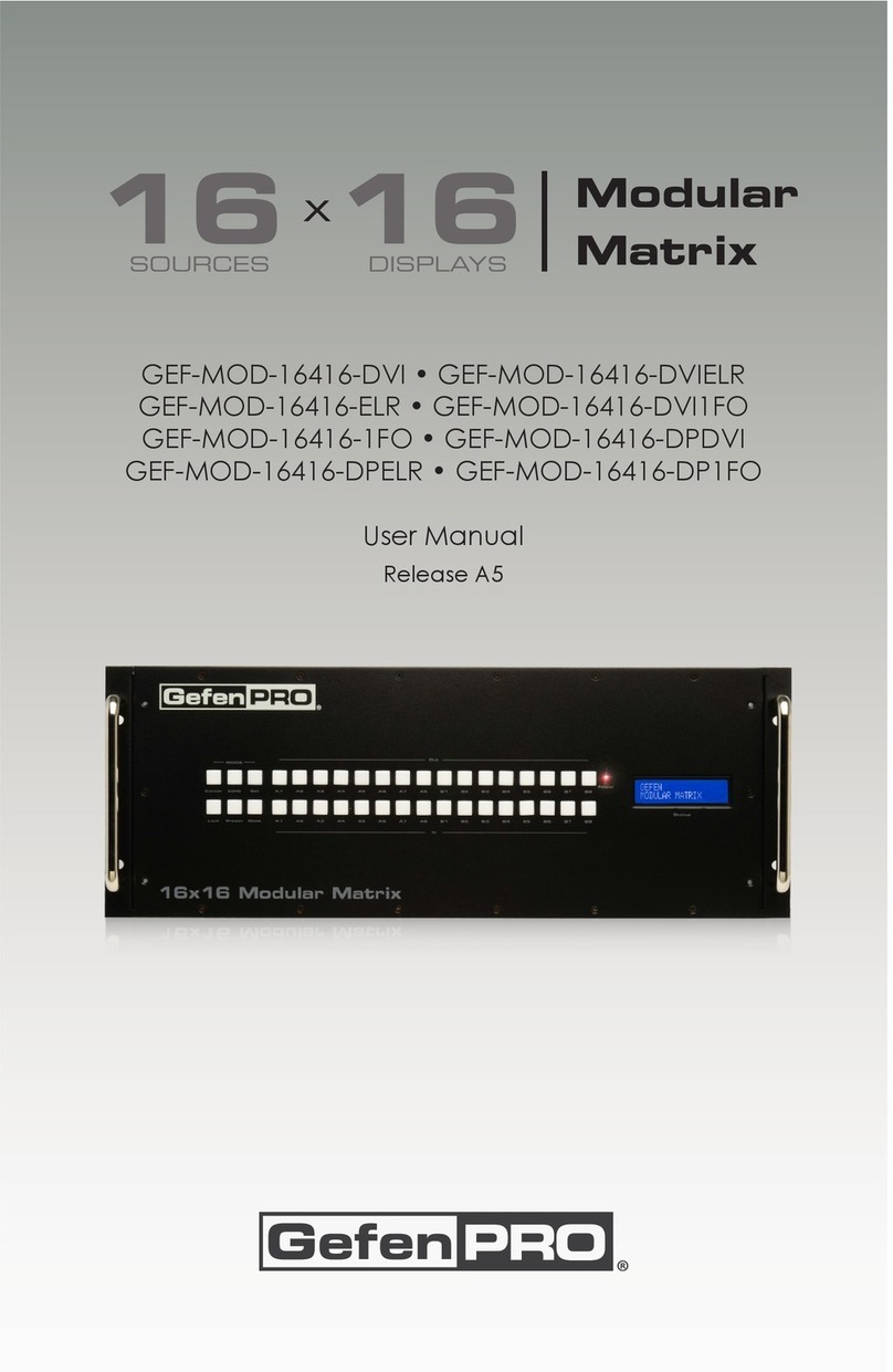
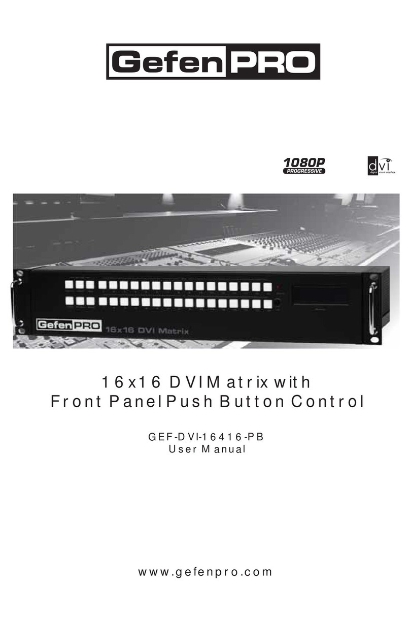
Gefen Pro GEF-DVI-16416 User manual

16x16 DVI Matrix
GEF-DVI-16416
User Manual
www.gefenpro.com
1080P

ASKING FOR ASSISTANCE
Technical Support:
Telephone (818) 772-9100
(800) 545-6900
Fax (818) 772-9120
Technical Support Hours:
8:00 AM - 5:00 PM Monday - Friday, Pacific Time
For 24 / 7 support, see the back of the product for the support number
Write To:
Gefen LLC
c/o Customer Service
20600 Nordhoff St
Chatsworth, CA 91311
www.gefenpro.com
Notice
Gefen LLC reserves the right to make changes in the hardware, packaging and
any accompanying documentation without prior written notice.
16x16 DVI Matrix is a trademark of Gefen LLC
© 2010 Gefen LLC, All Rights Reserved
All trademarks are the property of their respective owners
Rev C10
4.10

CONTENTS
1 Introduction
2 Operation Notes
3 Features
4 Front Panel Layout
5 Front Panel Descriptions
6 Back Panel Layout
7 Back Panel Descriptions
8 Connecting And Operating The GefenPRO 16x16 DVI Matrix
8 Wiring Diagram
9 Front Panel Display
11 IR Remote Description
12 IR Remote Installation
13 IR Remote Configuration
14 EDID Management Feature
15 RS-232 Serial Control Interface
16 RS-232 Serial Control Commands
16 Commands
19 EDID Management
24 IP Configuration
27 General Functions
31 IP Control
31 Main Page
32 Manage EDID
36 Masking
37 IP Configuration
38 Backup / Restore & Power Management
39 Firmware Update
41 Rack Mount Safety Information
42 Specifications
43 Warranty
44 Licensing

1
Congratulations on your purchase of the GefenPRO 16x16 DVI Matrix. Your
complete satisfaction is very important to us.
All GefenPRO products include 24/7 customer support from trained technical
service representatives available at Gefen. This enhanced customer service is
ideal for highly demanding industries such as broadcasting and the rental/staging
markets.
GefenPRO
In the realm of video distribution, certain features are invaluable in a commercial
or broadcast environment. Accommodations such as a build-in power supply
and flat black rack-mount enclosures set GefenPRO apart from our traditional
products. Complex distribution units allow for professional DVI, 3G-SDI, and
HDMI signals to be routed and converted easily and seamlessly, while being
backed up by a renowned and dependable technical support team. Gefen invites
you to explore the GefenPRO product line and hopes that you find the solution
that fits your needs.
The GefenPRO 16x16 DVI Matrix
Simplify the process of routing up to 16 DVI sources to any of 16 DVI monitors
without losing quality or resolution. The GefenPRO 16x16 DVI Matrix provides
a simple, reliable, and highly effective method of streamlining any installation
using multiple sources and outputs, taking the hassle out of managing multiple
connections. Each DVI source is accessible at all times by any monitor using the
front-panel buttons, IR remote unit, built-in RS-232 or using IP control.
How It Works
The GefenPRO 16x16 DVI Matrix has 16 DVI inputs and 16 DVI outputs. Using
the supplied DVI cables, connect 16 sources to the DVI input ports on the
GefenPRO 16x16 DVI Matrix’s input side. Connect the GefenPRO 16x16 DVI
Matrix’s 16 DVI outputs to the monitors. Plug in the power cord and power on the
GefenPRO 16x16 DVI Matrix. The connected monitors will show video according
to the routing selection.
NOTE: The GefenPRO 16x16 DVI Matrix only supports DVI-D. The DVI
connectors on the GefenPRO 16x16 DVI Matrix have all 29 pins.
INTRODUCTION

2
READ THESE NOTES BEFORE INSTALLING OR
OPERATING THE GEFENPRO 16X16 DVI MATRIX
• The GefenPRO 16x16 DVI Matrix does not support HDCP content.
• Make sure that a DVI monitor is powered and connected to one of the DVI
outputs on the GefenPRO 16x16 DVI Matrix before applying power. By
default, the Local EDID is read from the connected monitor and is copied
to all 16 DVI inputs once the Matrix has been turned on. If a monitor is not
detected by the Matrix at power-on, a default (internal) EDID of 640x480 will
be used. This functionality can be disabled using the Secure Local EDID
function through IP control. See page 21 for more information.
• There is no internal scaling in the GefenPRO 16x16 DVI Matrix. Each
monitor attached to the Matrix must be able to display the resolutions output
by the source device(s). For maximum compatibility it is recommended that
only one common resolution be used by each source device.
• Advanced EDID features and IP configuration features are accessible
through the RS-232 serial command set.
• Routing and EDID features can be managed using the built-in IP control
feature.
• IMPORTANT: If the unit is installed in a closed or multi-rack assembly, do
not block the ventilation holes of the enclosure.
OPERATION NOTES

3
Features
• Increases productivity
• Supports resolutions up to 1920x1200
• Front panel control buttons for local switching
• IP Control
• Serial RS-232 interface for remote control via a computer or control
automation devices
• Discrete IR remote control
• Advanced EDID management permits uploading of custom internal or
external EDID settings
• Supports DDWG standards for DVI
• Internal power supply
• Output masking command
• Standby mode
• Grounding pin
• IR Sensor
• IR Extender
• Power On/Off switch
• Status LCD (shows routing status)
• Rack mountable
Package Includes
(1) GefenPRO 16x16 DVI Matrix
(16) 6-foot DVI cable (M-M)
(1) IR remote control unit
(1) AC Power Cord
(1) User Manual
FEATURES

4
Front Panel
PANEL LAYOUT
2 3 4 51
6

5
PANEL DESCRIPTION
1 Control Buttons
These buttons are used to navigate the LCD menu system. See pages 7 and 8
for more information.
◄- Left
►- Right
Select - Select
2 Cancel Button
This button is used to cancel a routing change in progress.
3 IR Window
Receives signals from the IR Remote Control unit.
4 Power Indicator
This LED indicator will glow red when the power is turned on.
5 Power Switch
Turn the power on or off using this switch.
6 LCD Display
Displays the current routing status of the Matrix and is also used to manage
source routing.
Front Panel

6
PANEL LAYOUT
Back Panel
4
5
3
7 6
1 2

7
PANEL DESCRIPTIONS
1IR Extender Port
Connect an IR extender cable to this port.
2 110 / 220 V AC (50/60 Hz) Power Cable Receptacle
Connect the included AC power cord from this receptacle to an available
electrical outlet.
3 DVI Input Ports (1 - 16)
Connect DVI source devices to these ports.
4 IP Control Interface
Connect to this port to control the 16x16 DVI Matrix using IP Control. See page
26 for more information.
5 Grounding Terminal
Provides a discharge path to ground in case a short circuit occurs between the
“hot” lead of the power supply and the enclosure of the Matrix. The grounding
wire should be attached from the grounding terminal to an approved ground
path.
6 DVI Output Ports (1 - 16)
Connect DVI monitors to these ports.
7 RS-232 Serial Port
Connects to the RS-232 control device. The 16x16 DVI Matrix may be switched
remotely using this port. See page 24 for more information.
Back Panel

8
How to Connect the GefenPRO 16x16 DVI Matrix
1. Connect up to 16 DVI source devices to the DVI inputs on the rear panel of
the GefenPRO 16x16 DVI Matrix using the supplied DVI cables.
2. Connect up to 16 DVI monitor to the DVI outputs on the rear panel of the
GefenPRO 16x16 DVI Matrix with user-supplied DVI cables.
3. Connect the included AC power cable to the power receptacle on the rear
panel of the GefenPRO 16x16 DVI Matrix. Connect the opposite end of the
cable into an available electrical outlet.
4. Power on the monitors and the source devices. Turn on the GefenPRO
16x16 DVI Matrix by pressing the power switch on the front panel.
How to Operate the GefenPRO 16x16 DVI Matrix
The GefenPRO 16x16 DVI Matrix offers a number of control options. The
following methods can be used to control basic routing functions of the
GefenPRO 16x16 DVI Matrix:
1. Front Panel Control Buttons - Pages 9 and 10
2. IR Remote Control - Pages 11 - 13
3. RS-232 Serial Control - Pages 15 - 30
4. IP Control - Pages 31 - 38
CONNECTING AND OPERATING
THE GEFENPRO 16X16 DVI MATRIX
GEF-DVI-16416
DVI Displays
DVI CABLE
16x
DVI Sources
16x
Matrix
Attention: This product should always be connected to a grounded
electrical socket.

9
FRONT PANEL DISPLAY
MAIN DISPLAY
The Main Display of the GefenPRO 16x16 DVI Matrix is a 16 character 2 line
display. This display will show the standby screen and will also be used to aid
in performing routing commands. When the unit is powered on, the following
screen is displayed:
After a few moments, the Standby Screen is displayed. The Standby Screen is
shown below:
Displaying the Firmware Version
Pressing the ◄button on the front panel will display the current firmware
version:
Displaying the Bootloader Version
Press the ◄button to display the bootloader version:
Press the ◄button once more to return to the Standby Screen.
NOTE: The Cancel button can be pressed at any time to return to the Standby
Screen.

10
Routing Sources
Example:
Route the source device connected to In 2 to the monitor connected to Out 1.
1. From the Standby Screen, press the Select button on the front panel to
display the routing status screen.
2. Press the Select button again to move the cursor to INPUT.
3. Press the ►button to set the source to Input 2. The source device
connected to In 2 is now routed to the monitor connected to Out 1.
4. Press the Cancel button to return to the standby screen.
NOTE: The Cancel button can be used to return to the standby screen at
any time.
Displaying the Routing Status
From the main screen, press the Select button. When the arrow cursor is next
to OUTPUT, pressing the ◄or ►buttons on the front panel will show the current
routing state of each input and output. The illustration below shows the routing
state of output 1.
Pressing the ►button again will display the routing state of output 2 and so on.
Note that the number displayed next to INPUT may be different than the
illustration above, depending upon the current routing state.
FRONT PANEL DISPLAY

11
1 Activity Indicator
This LED will be activated momentarily each time a button is pressed.
2 Display and Source Selection Buttons
These buttons are used to select which source is routed to a monitor.
Routing Sources using the Remote Control unit
Issuing a routing command is a two step process. The first step is to select the
monitor (1-16) to which the source will be routed. The second step is to select the
source (1-16).
Example:
Route the source device connected to In 6 to the monitor connected to Out 4.
1. Press button 4 (Out 4) on the IR remote control unit.
2. Press button 6 (In 6) on the IR remote control unit.
The source connected to In 6 will be routed to the monitor connected to Out 4.
IR REMOTE DESCRIPTION
RMT-16416IR
Remote Control Unit
1
2

12
IR REMOTE INSTALLATION
Installing the RMT-16416IR Battery
1. Remove the battery cover on the back of the IR Remote Control unit.
2. Insert the included battery into the open battery slot. The positive (+) side of
the battery should be facing up.
3. Replace the battery cover.
The Remote Control unit ships with two batteries. One battery is required for
operation and the other battery is a spare.
CAUTION: Risk of explosion if battery is replaced by an incorrect type.
Dispose of used batteries according to the instructions.
Battery Slot

13
IR REMOTE CONFIGURATION
How to Resolve IR Code Conflicts
In the event that IR commands from other remote controls interfere with the
supplied IR Remote Control unit, changing the IR Remote Control’s IR channel
will fix the problem. The IR Remote Control unit has a bank of DIP switches used
for setting the IR channel.
The DIP switch bank is located underneath the battery cover.
1 2 1 2
1 2
1 2
Remote Channel 2:
Remote Channel 0:
Default
Remote Channel 1:
Remote Channel 3:
Left: Picture of the opened rear battery
compartment of the IR remote showing the
exposed DIP Switch bank between the battery
chambers.
It is important that the IR channel on the Remote Control unit, matches the
IR channel set on the GefenPRO 16x16 DVI Matrix. For example, if both
DIP switches on the IR Remote Control unit are set to IR channel 0 (both DIP
switches down), then the GefenPRO 16x16 DVI Matrix must also be set to IR
channel 0. See page 25 on how to change the IR channel on the GefenPRO
16x16 DVI Matrix.

14
EDID. What is it and what is it used for?
Under normal circumstances, a source device (digital and analog) will require
information about a connected device/display to assess what resolutions
and features are available. The source can then tailor its output to send
only resolutions and features that are compatible with the attached device/
display. This information is called EDID (Extended Display Information Data)
and a source device can only accept and read one EDID from a connected
device/display. Likewise, the source an only output one resolution for use by a
connected device/display.
Why is EDID so important with the GefenPRO 16x16 DVI Matrix?
The GefenPRO 16x16 DVI Matrix is a complex piece of technology that
replicates and switches between multiple inputs and outputs. Each connected
source device will require one EDID to read. EDID management is carefully
handled by the GefenPRO 16x16 DVI Matrix to provide a single EDID for each
source to read.
What options do I have to manage the EDID in the GefenPRO 16x16 DVI
Matrix?
First, it is important to note that each source device can only output one video/
audio signal type. This includes resolutions and timings. When multiple devices/
displays are used, such as with the GefenPRO 16x16 DVI Matrix, it is important
to use devices/displays that have similar or compatible resolutions and features.
This will ensure that the single video/audio signal produced by the source device
is accepted by all of the connected output devices/displays.
The user has the option, through utilization of the RS-232 serial interface, to
choose how the unit will manage the EDID from multiple DVI devices/displays.
Therefore the user has some control over the resolutions and features that the
source devices will output. The GefenPRO 16x16 DVI Matrix has a LOCAL EDID
management mode that will control how the EDID information is handled.
How do I change EDID modes in the GefenPRO 16x16 DVI Matrix?
EDID modes and IP configuration is managed via the RS-232 serial
communications port. See page 13 for more information on the RS-232 serial
communication features.
EDID MANAGEMENT FEATURE

15
What features are available via the RS-232 serial communications port?
The GefenPRO 16x16 DVI Matrix can accept commands through the RS-232
serial communications port located on the rear panel. The current RS-232 control
features are:
• Switching/routing of inputs to outputs without the IR remote control.
• Managing the EDID bank and EDID that is loaded into the LOCAL EDID.
• Upload new EDID’s to the EDID bank or directly to the LOCAL EDID
location.
• Manage IP settings.
How do I use these features?
These features were initially intended for utilization by custom installers in
automated setups. However, these features can be tested and used by using any
Windows PC with a terminal program.
What pins are used for communication with the GefenPRO 16x16 DVI
Matrix?
Only pins 2 (Receive), 3 (Transmit), and 5 (Ground) are used for communication.
A null-modem adapter should not be used with this product.
54321
9876
12345
6789
Only Pins 2 (RX), 3 (TX), and 5 (Ground) are used on the RS-232 serial interface
RS-232 Settings
Bits per second ............................................................................................ 19200
Data bits ............................................................................................................... 8
Parity ............................................................................................................. None
Stop bits ................................................................................................................1
Flow Control .................................................................................................. None
RS-232 SERIAL CONTROL INTERFACE

16
RS-232 SERIAL CONTROL COMMANDS
RS-232 Features
RS-232 remote functions are used to control of this product’s features. Features
include input to output routing, EDID storage, EDID management, etc.
Functions Syntax
The syntax for each function is always the same:
#Character as the start flag →Function name →Space ( _ ) as function name
end flag →Parameter 1 →Space ( _ ) →Parameter n →Carriage Return ( \r )
Sample:
#FunctionName_param1_param2_param3_param4...\r
Syntax is NOT case sensitive.
Commands
Simplified syntax was used for command implementation for faster operation with
the device: # character – isn’t needed, the command name is reduced to 1 letter.
The commands are not case-sensitive.
Command Description
RRouting command
SRoutes a single input to all outputs
MReturns the current routing status of matrix
FToggle 5V fiber optic extender feature
R Command
The R command allows specific routing of inputs and outputs.
Syntax:
r param1 param2
Parameters:
param1 DVI Ouput [1 - 16]
param2 DVI Input [1 - 16]

17
RS-232 SERIAL CONTROL COMMANDS
S Command
The S command routes a single input to all 16 DVI outputs.
Syntax:
s param1
Parameters:
param1 Input [0 - 16]
Notes:
Setting param1 to a value of 0 will place the matrix in one-to-one mode. This
means that Input1 will be routed to Output1, Input2 will be routed to Output2, and
so on.
M Command
The M command displays the current routing status of the matrix.
Syntax:
m
Parameters:
None
Table of contents
Other Gefen Pro Matrix Switcher manuals

Gefen Pro
Gefen Pro GEF-HDFST-848-4ELR User manual

Gefen Pro
Gefen Pro GEF-HDFST-444-4ELR User manual

Gefen Pro
Gefen Pro GEF-DVIKVM-848DL User manual

Gefen Pro
Gefen Pro GEF-DVI-1044DL User manual

Gefen Pro
Gefen Pro GEF-MOD-32432-DVI User manual

Gefen Pro
Gefen Pro GEF-DVI-848DL User manual

Gefen Pro
Gefen Pro GEF-HDFST-MOD-16416-HD User manual

Gefen Pro
Gefen Pro GEF-3GSDI-16416 User manual

Gefen Pro
Gefen Pro GEF-DVI-848DL-PB User manual

Gefen Pro
Gefen Pro GEF-DVI-16416-PB User manual