Gefen Pro 3GSDI User manual

3GSDI to 3GSDI
Scaler
GEF-3GSDI-2-3GSDIS
User Manual
1080P
www.gefenpro.com
2K


ASKING FOR ASSISTANCE
Rev A1
Technical Support:
Telephone (818)772-9100
(800)545-6900
Fax (818)772-9120
Technical Support Hours:
8:00AMto5:00PMMondaythroughFriday,PacicTime
For24/7support,seethebackoftheproductforthesupportnumber
Write To:
Gefen,LLC.
c/oCustomerService
20600NordhoffSt
Chatsworth,CA91311
www.gefenpro.com
Notice
Gefen,LLCreservestherighttomakechangesinthehardware,packaging,andany
accompanyingdocumentationwithoutpriorwrittennotice.
3GSDI to 3GSDI Scaler isatrademarkofGefen,LLC
HDMI,theHDMIlogo,andHigh-DenitionMultimediaInterfacearetrademarksor
registeredtrademarksofHDMILicensingintheUnitedStatesandothercountries.
©2012Gefen,LLC.Allrightsreserved.
Alltrademarksarethepropertyoftheirrespectiveowners.

CONTENTS
1 Introduction
2 OperationNotes
3 Features
4 PanelLayout
5 PanelDescriptions
6 IRRemoteLayoutandDescription
7 IRRemoteControlInstallation
7 InstallingtheBattery
7 SettingtheIRChannel
8 ConnectingThe3GSDITo3GSDIScaler
8 WiringDiagram
9 MenuSystem
9 GeneralMenu
10 PatternsMenu
10 OutputMenu
11 InputMenu
13 PictureMenu
15 LayoutMenu
15 AspectMenu
17 RS-232SerialControl
18 RS-232Commands
33 SupportedVideoandGraphicsFormats
36 RackMountSafetyInformation
37 MountingPlateInstallation
38 AppendixA
38 GammaLUTFileFormat
39 Specications
40 Warranty

1
INTRODUCTION
Congratulationsonyourpurchaseofthe3GSDIto3GSDIScaler.Yourcomplete
satisfactionisveryimportanttous.
GefenPRO
Intherealmofvideodistribution,certainfeaturesareinvaluableinacommercialor
broadcastenvironment.Accommodationssuchasabuild-inpowersupplyandatblack
rack-mountenclosuressetGefenPROapartfromourtraditionalproducts.Complex
distributionunitsallowforprofessionalDVI,3G-SDI,andHDMIsignalstoberoutedand
convertedeasilyandseamlessly,whilebeingbackedupbyarenownedanddependable
technicalsupportteam.GefeninvitesyoutoexploretheGefenPROproductlineandhopes
thatyoundthesolutionthattsyourneeds.
The GefenPRO 3GSDI to 3GSDI Scaler
TheGefenPRO3GSDI-2-3GSDISprovideshigh-performancescaling-includingadjustable
cadencedetection,framerateconversion,detailenhancement,andadvancednoise
reduction.
ItworkswithSDI,ED-SDI,HD-SDI,or3G-SDIsignalsandsupportsresolutionsupto
1080pFullHDand2048x1080(2K).
Thisproductcanbeusedasastandaloneframesynchronizerwithoutscalingifdesired.
Whenframesynchronizationisrequired,thevideooutputofonesource(orareference
signal)canbeusedtoGenlockanotherinputsource.GenlockMode,aswellasallfeatures
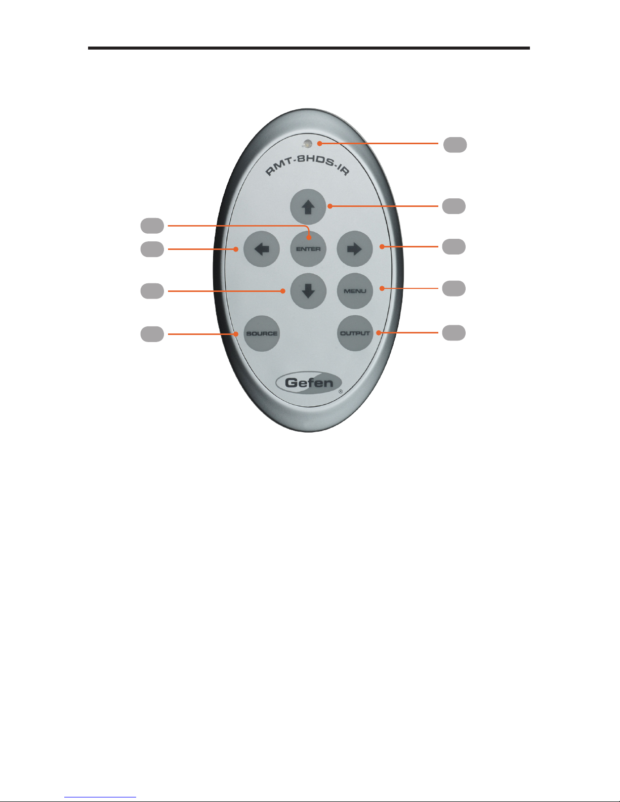
ofthisscaler,canbecontrolledthroughthebuilt-inmenusystemusingtheIRRemote
ControlorviaRS-232control.
How It Works
ConnectSDIsourcedevicestotheSDIinputsandconnectdownstreamequipmenttothe
SDIoutputs.ConvenientSDIloop-throughoutputconnectorsandanRCACoax(S/PDIF)
audiooutputallowmonitoringofSDIvideoandaudio.AnexternalGenlocksourcemayalso
beconnected.
CongurationmaybedoneusingtheIRRemoteandtheOn-ScreenDisplay(OSD)menu,
orviatheRS-232port.AUSBportisalsoprovidedforfuturermwareupgrades.

OPERATION NOTES
2
READ THESE NOTES BEFORE INSTALLING OR
OPERATING THE 3GSDI TO 3GSDI SCALER
• Thebuilt-inGUI(GraphicalUserInterface)orOn-ScreenDisplay(OSD)provides
convenientoperationoftheScaler.ThesuppliedIRRemotecontroloperatesthe
OSD.Seepages9-16fordetailsontheOSDcommands.
• TheIRRemoteControlunit’sIRchannelmustbeidenticaltothatoftheScaler.See
page30fordetailsonconguringtheIRChannelonthe3GSDIto3GSDIScaler.
• The3GSDIto3GSDIScalersupportsmanyinputandoutputresolutions.
Foracompletelistofsupportedformats,seepages33-35.
• SupportsSMPTEstandards259M,292M,SMPTE274M,SMPTE296M,ITU-R
BT.656andITU-RBT.601.Handles3G-SDISMPTE425-Aand425-B/formats1080p
50/59.94/60.
• Internalsoftware(rmware)maybeupgradedviathebuilt-inSerialorUSBports.Note
thatsoftwareupdatesperformedontheUSBportwillbequickerduetoitshigherdata
transferrate.

3
FEATURES
Features:
• Digitalaudiooutput
• Adjustablecadencedetection
• Advancednoisereductionanddetailenhancement
• Frame-rateconversion
• Fullyintegratedsprite-basedMenuSystem
• Built-inpatterngeneratorwithColorBarsandHatchPattern
• RS-232Control
• IRRemoteControl(included)
• Field-upgradeablermwareviaUSBport
• Rack-mountable(rackearsincluded)
Package Includes
(1)GefenPRO3GSDIto3GSDIScaler
(1)IRRemoteControl
(1)ACPowerCord
(1)SetofRackEars
(1)Quick-StartGuide

4
PANEL LAYOUT
Front Panel
Back Panel
1
4 6
5 7
8 9
2 3
10 11

5
PANEL DESCRIPTIONS
1 IR
ReceivessignalsfromtheincludedIRRemoteControlunit.
2 3GSDI
ThisLEDwillglowbrightbluewhen3GSDIsignalsaredetectedontheinput.
3 Power
ThisLEDwillglowbrightbluewhentheunitispowered.
4 USB
ConnectaUSBcablefromacomputertothisUSBportwhenupdatingthermware.
5 Genlock
Usedtogenerator-lock(“genlock”)thevideosourcewithanexternalreferencesignal.
ConnectaBNCcablebetweenthe“genlock”deviceandtheGenlockBNCconnector.
6 Coax
ConnectaCoaxcablefromthisS/PDIFconnectortoanaudiooutputdevice.
7 InA,InB
ConnectBNCcablesfromthe3GSDIsourcetotheseconnectors.
8 LoopOutA,LoopOutB
ConnectBNCcablesfromtheseconnectorstoalocalSDImonitoringdisplay.TheLoop
Outconnectorspass-throughthesourcesignalwithoutanyprocessing.
9 OutA,OutB
ConnectBNCcablesfromtheseconnectorstoanSDIdisplay.
10 PowerReceptacle
ConnecttheincludedACpowercordfromthispowerreceptacletoan
availableelectricaloutlet.
11 PowerSwitch
Pressthisswitchtopower-onorpower-offthescaler.

6
IR REMOTE LAYOUT AND DESCRIPTIONS
RMT-8HDS-IR
1.LEDindicator-glowsbrightorangewheneverakeyispressed,indicatingthe
transmissionofanIRcommandtotheScaler.
2. TheENTERbuttonactivatesaselectedmenuoptionintheOn-ScreenDisplay.
3. LEFTdirectionkeyformenunavigationwithintheOn-ScreenDisplay.
4. DOWNdirectionkeyformenunavigationwithintheOn-ScreenDisplay.
5. Source-Cyclesbetweenavailableinputsources.Theselectableinputsare3GSDI
Input1and3GSDIInput2.PressonceforInput1;twiceforInput2.
6. Output-Cyclesthroughtheavailableoutputresolutions.Seepages33-35foralistof
outputresolutions.
7. Menu-DisplaystheOn-ScreenDisplaymenusystemforcontroloftheScaler.
8. RIGHTdirectionkeyformenunavigationwithintheOn-ScreenDisplay.
9. UPdirectionkeyformenunavigationwithintheOn-ScreenDisplay.
1
2
3
4
5
9
8
7
6

IR REMOTE CONTROL INSTALLATION
7
Installing the Battery
TheRemoteControlunitshipswithtwobatteries.Onebatteryisrequiredforoperationand
theotherbatteryisaspare.
1. RemovethebatterycoveronthebackoftheIRRemoteControlunit.
2. Inserttheincludedbatteryintotheopenbatteryslot.Thepositive(+)sideofthe
batteryshouldbefacingup.
3. Replacethebatterycover.
Setting the IR Channel
TheIRchannelontheIRRemoteControlmustmatchtheIRchannelusedbythe3GSDI
to 3GSDI Scaler.Forexample,ifbothDIPswitchesontheIRRemoteControlunitareset
toIRchannel0(bothDIPswitchesdown),thenthe3GSDI to 3GSDI Scalermustalsobe
settoIRchannel0.Seepage30forinformationonhowtochangetheIRchannelonthe
3GSDI to 3GSDI Scaler.
WARNING: Riskofexplosionifbatteryisreplacedbyanincorrect
type. Disposeofusedbatteriesaccordingtotheinstructions.
RemoteChannel2: RemoteChannel3:
Channel0(default): RemoteChannel1:
Batteryslot
1 2
ON
1 2
ON
1 2
ON
1 2
ON
1 2
DIPswitches
NOTE: AnActivityIndicatorthatashesquicklywhileholdingdown
anyoneofthe8buttonsindicatesalowbattery.ReplacetheIR
RemoteControlbatteryassoonaspossible.

8
CONNECTING THE 3GSDI TO 3GSDI SCALER
How to Connect the 3GSDI to 3GSDI Scaler
1. Connecta3GSDIsourcetotheInAconnectoronthe3GSDIto3GSDIScaler.
2. ConnecttheOutAportonthebackoftheScalertoa3GSDIdisplay.The3GSDI
destinationcabbemirroredbyconnectingaBNCcablefromtheOutBporttoa
secondary3GSDIdisplay.
3. ConnectacoaxcablefromtheS/PDIFoutputtoanexternalamplier.
4. Ifmonitoringofthe3GSDIsourceisdesired,connectaBNCcablefromtheLoopOut
Aconnectortothe3GSDIdisplay.TheLoopOutconnectorspass-throughthesource
signalwithoutanyprocessing.
5. ConnecttheincludedACpowercordfromthepowerreceptacletoanavailable
electricaloutlet.
6. Powerthe3GSDIto3GSDIScalerbypressingthepowerswitchontherearofthe
unit.
Wiring Diagram for the 3GSDI to 3GSDI Scaler
NOTE:Inordertooutputduallink1080pwhenusingHD-SDI,
boththeOutAandOutBmustbeconnectedtothe3GSDIdisplay.
WARNING:Thisproductshouldalwaysbeconnectedtoa
groundedelectricalsocket.
GEF-3GSDI-2-3GSDIS
S/PDIF CABLE
SDI CABLE
RS-232 CABLE
3G-SDI Source
Scaler
00:00:00
Audio Receiver
3G-SDI Display
Clock Generator
RS-232 Controller

9
MENU SYSTEM
General Menu
Information
ToaccesstheGeneralMenu,presstheMenubuttonontheIRRemoteControlUnit.The
GeneralMenuwillbetherstmenudisplayedoncontainsinformationabouttheScaler:
• HostFirmwareVersion
• KernelVersion
• CongurationVersion
• FPGAVersion
• RemoteChannel
General > Language
FromtheGeneralMenu,pressthe▼buttonontheIRRemoteControlUnit.Selectthe
Languageusingthe►and▼buttonsontheIRRemoteControlUnit.PresstheMenu
buttontoexitthemenusystem.
• English
• French
General > Save Conguration
TheSaveCongurationfeatureisusedtosavethecurrentcongurationoftheScaler.
Oncethecurrentcongurationissaved,thesesettingswillberestoredeachtimetheScaler
ispowered.
General > Restore Default Conguration
RestorestheScalertofactorydefaultsettings.Usethisfeaturetorestoredefaultcongu-
rationsiftheyhavebeenoverwrittenbyusingtheSaveCongurationfunction.
WARNING:Thisfunctionwilloverwriteanypreviouslysaved
conguration,includingthefactorydefaultsettings.Torestore
thefactorydefaultsettings,pressthefollowingbuttonsinorder:
Left,Right,andOKbuttons.Donotdepressallthreebuttons
simultaneously.

10
MENU SYSTEM
Patterns Menu
Patterns > Color Bars
Producesacolorbarpattern,similartoastandardSMPTEbarpatternusedforcolor
calibration.
Patterns > Hatch Pattern
Producesacrosshatchpattern.Thispatterncanbeusedfor“pincushion”testing
(curvatureoftheimageonthescreen)orcolorconvergence/divergence.
Output Menu
The3GSDIoutputsignalcanbeconguredfromtheOutputmenu.TheOutputmenu
controlsseveralfunctions,suchasresolution,linkconguration(singlelinkorduallink),
genlockreference,andgenlockoffset.
Output > Output Format
Selectstheoutputresolution.Seepages33-35fordetailsonavailableoutputformats.
Output > Link Conguration
Selectsthelinkcongurationinrespecttocolorspace.WhenusingduallinkSDIorHD-
SDIinput,YCbCrorRGBcanbeselected.If3G-SDIisused,AorB(4:2:2only)canbe
selected.
• SingleLinkYCbCr4:2:2(SD/HD/3G)
• SingleLink1080p(3GLevelB)
• DualLinkYCbCr(HD)
• DualLinkRGB(HD)
• DualLink1080p/576p/480p(HD)
NOTE: Whenapatternisproduced,thecurrentvideoimagewillbe
masked.

11
MENU SYSTEM
Output > Genlock Reference
Thisoptionenablesordisabledtheautomaticgenlockmode.
• Off
Disabledgenlock
• VideoInput
Usesthevideoinputasthereferenceclock.
• RefInput
UsestheclockattachedtotheRefInconnectoronthebackoftheunit.
Output > Genlock Offset
Thisoptionprovidestheoptiontoadjusttheoutputlinesandoutputpixels.
• OutputLines
• OutputPixels
Input Menu
Input > Input Video Format
Selectstheresolutionandtimingoftheinputformat.Bydefault,thisissettoAutoDetect
whichautomaticallysensestheresolutionandtimingoftheinputsignal.Theavailable
resolutionsunderthismenuareinSDandHDformat.
Input > Graphic Format
Selectstheresolutionandtimingoftheinputformat.Bydefault,thisissettoAutoDetect
whichautomaticallysensestheresolutionandtimingoftheinputsignal.Theavailable
resolutionsunderthismenuareinVESAformat.

12
MENU SYSTEM
Input > Clean Aperture
Allowsadjustmentoftheinputsignalposition.Thecleanapertureparametersallowan
areawithintheproductionaperturetobedened.Theminimumcleanaperturesizeis0
pixelsby0lines.
• HorizontalSize
Adjuststhehorizontalsizeoftheimage.
• VerticalSize
Adjuststheverticalsizeoftheimage.
• HorizontalPosition
Adjuststhehorizontalpositionoftheimage.
• VerticalPosition
Adjuststheverticalpositionoftheimage.
Input > Film Mode
Automaticallydetectsrepeatedeldsequencespresentininterlacedsignals,suchas:50
Hzor60Hzeldsequences(norepeatedelds),60Hz3:2pull-down,includingbroken/
editedsequencedetection,60Hz2:2:pull-down,50Hz2:2pull-down,andFreezeframe.
• Enable
• Disable
Input > Remote Channel
ThisoptionchangestheIRchannelofthe3GSDIto3GSDIScalertooneof4different
settingsbetween0and3.WhentheremotechanneloftheScalerischanged,theDIP
switchesintheeight-buttonremotemustbechangedtothecorrespondingIRchannel
inordertooperatetheScaler(seeIRRemoteControlInstallationonpage7formore
information).

13
MENU SYSTEM
Input > Input Color Range
TheRGBoutputcolorrangemaybechanged/settolimited(16-235)ortofull(0-255).
• Auto
Usesthecolorrangeoftheinputsignal.
• 16-235(Passthrough)
Theinputcolorrangewillbecompressedfromfull-range(0-255)tolimited-range.
• 0-255(Compress)
Theoutputcolorrangewillbeexpandedfromlimited-range(16-235)tofull-range
(0-255).
Picture Menu
Picture > Image Color
AllowsindividualadjustmentoftheRed,Green,andBluecolorcomponents,brightness,
andBlackLeveloftheimage.
• Red
AdjuststhesaturationoftheRedcolorcomponent.
• Green
AdjuststhesaturationoftheGreencolorcomponent.
• Blue
AdjuststhesaturationoftheBluecolorcomponent.
• Brightness Red
AdjuststhebrightnessoftheRedcolorcomponent.
• Brightness Green
AdjuststhebrightnessoftheGreencolorcomponent.
• Brightness Blue
AdjuststhebrightnessoftheBluecolorcomponent.
• RGB/Y Output Offset
Adjuststheblackleveloftheimage.

14
MENU SYSTEM
Picture > Gamma Correction
• Default
SetsthedefaultGammasettings.
• sRGB
GammacorrectionusedwithPCs,cameras,andprinters.
• User Table
ThisoptionisusedwithauserGammaLUT.Seepages38fordetailsonusinga
GammaLookUpTable.
• Custom Table
UsewhendeningacustomLUT.Seepages38fordetailsonusingaGammaLook
UpTable.
• Gamma Coeffecient
AdjuststheGammacoeffecientintherangefrom0.3to3.0.ThedefaultGamma
valueis1.0.
Picture > Detail Enhancement
Theseparametersprocessestheinputdataineitherprogressiveorinterlacedformat.
Changestothedetailenhancementareimplementedatthestartofthenextframeofvideo.
Bothoftheseparameterscanbeadjustedwithintherangeor0-100.
• DetailEnhancement
• NoiseThreshold
Picture > Noise Reduction
Thisisanadaptivenoisereductionfunctionwhichprocessestheinputdataineither
progressiveorinterlacedformat.EnablingtheNoiseReductiontonoisyinterlacedsignals
canoptimizede-interlacerperformance.
Picture > Motion Threshold
ThissetstheintraframemotiondetectionthresholdforthedeinterlacerontheVXP
processor.Videoartifactscanbecreatedwhende-interlacing(creatinginterlacedelds
fromprogressiveelds).Thisfunctionallowsadjustmentofthethresholdusedbythe
deinterlacermotiondetectionalgorithm,removing/minimizingmotionartifactsinthe
convertedvideo.
NOTE: WhentheCustomLUT(LookUpTable)isselected,the
GammacoefcientisusedtocalculateanewGammaLUT.

15
MENU SYSTEM
Layout Menu
Layout > Size and Position
Setthesizeandthepositionoftheimage.Notethatthisoptionisnotavailableinthe
panoramicaspectmode.
• Horizontal Size
Setshorizontalsizeoftheoutputsignal.
• Vertical Size
Setsverticalsizeoftheoutputsignal.
• Horizontal Position
Setshorizontalpositionoftheoutputsignal.
• Vertical Position
Setsverticalsizeoftheoutputsignal.
Aspect Menu
Aspect > Full Screen
Stretchestheoutputsignaltollthedisplay.
Aspect > Letter / Pillar Box
Setstheaspectrationtotaletterorpillarboxformat.
Aspect > Panoramic
Setstheoutputsignaltopanoramicformat.

16
MENU SYSTEM
Aspect > Extract
ThisafunctionallowstheScalertozoominonasubsetoftheinputvideosignal.This
featureallowyoutozoomononeselectedsectionoftheinputpicture.
• Extract Size
Selectsthesizeofthesubsettobeextractedinpercentageoftheinput.
• HorizontalPosition
Movesthepictureleftorright(withintheoriginalinputfullsizeinput).
• VerticalPosition
Movesthepictureupordown(withintheoriginalinputfullsizeinput).
Aspect > Through
Thisfunctiondenesasub-windowthatisalwayscenteredonthescreen.Thepositionis
therelativepositionofthewindowwithinthefullpicture.Thisfeatureallowyoutodisplay
oneselectedsectionoftheinputpicturewithoutmodifyingitssize.
• HorizontalSize
Adjuststhesizeofthesub-windowhorizontally.
• VerticalSize
Adjuststhesizeofthesub-windowvertically.
• HorizontalPosition
Horizontallyadjuststherelativepositionofthewindowwithinthefullpicture.
• VerticalPosition
Verticallyadjuststherelativepositionofthewindowwithinthefullpicture.
NOTE: Whenchangingtheinputformat,theScalerwilltryandapply
thecurrentsettingstothenewinputformat.Ifthisisnotpossible
(e.g.thevalueisbeyondthezoomlimit),thenthedefaultvalue
(100%size)willbeused.
Other manuals for 3GSDI
1
This manual suits for next models
1
Table of contents
Other Gefen Pro Media Converter manuals
Popular Media Converter manuals by other brands

Asian Pro
Asian Pro APX 1502 user manual

SOMFY
SOMFY animeo 1860125 installation guide

Techly
Techly IDATA DP-102 user manual

GRASS VALLEY
GRASS VALLEY 8920ADC - datasheet

CTC Union
CTC Union IMC-1000MS-PH12 Quick installation guide

Planet Networking & Communication
Planet Networking & Communication ICS-100 user manual