manuals.online logo
Brands
  1. Home
  2. •
  3. Brands
  4. •
  5. Gehl
  6. •
  7. Construction Equipment
  8. •
  9. Gehl 600 Series Manual

Gehl 600 Series Manual

Other Gehl Construction Equipment manuals

Gehl RS5-34 User manual

Gehl

Gehl RS5-34 User manual

Gehl 700 Series Manual

Gehl

Gehl 700 Series Manual

Gehl AL 140 User manual

Gehl

Gehl AL 140 User manual

Gehl PowerBox 1639 User manual

Gehl

Gehl PowerBox 1639 User manual

Gehl 1448 Plus User manual

Gehl

Gehl 1448 Plus User manual

Popular Construction Equipment manuals by other brands

SASFORKS EXTREME manual

SASFORKS

SASFORKS EXTREME manual

Hailo H-50 manual

Hailo

Hailo H-50 manual

Graco LineLazer ES 1000 Operation - repair - parts

Graco

Graco LineLazer ES 1000 Operation - repair - parts

Greenlee 555RSC instruction manual

Greenlee

Greenlee 555RSC instruction manual

Manitowoc Grove CD3340B Service manual

Manitowoc

Manitowoc Grove CD3340B Service manual

Lux Tools A-FMR-20 Set manual

Lux Tools

Lux Tools A-FMR-20 Set manual

SIP 03683 manual

SIP

SIP 03683 manual

Volvo L30G Operator's manual

Volvo

Volvo L30G Operator's manual

Grizzly G8712 instruction sheet

Grizzly

Grizzly G8712 instruction sheet

Modulift CMOD 12 User instructions

Modulift

Modulift CMOD 12 User instructions

Case DV201 Service manual

Case

Case DV201 Service manual

Sealey SC10.V2 instructions

Sealey

Sealey SC10.V2 instructions

Wacker Neuson DT05 Operator's manual

Wacker Neuson

Wacker Neuson DT05 Operator's manual

HYVA AMCO VEBA 81 Series WARNING, OPERATING AND MAINTENANCE MANUAL

HYVA

HYVA AMCO VEBA 81 Series WARNING, OPERATING AND MAINTENANCE MANUAL

Atlas Copco Dynapac V5100TV manual

Atlas Copco

Atlas Copco Dynapac V5100TV manual

Toro 323 Operator's manual

Toro

Toro 323 Operator's manual

Manitowoc National Crane 1400A Operator's manual

Manitowoc

Manitowoc National Crane 1400A Operator's manual

SGS EC1500 owner's manual

SGS

SGS EC1500 owner's manual

manuals.online logo
manuals.online logoBrands
  • About & Mission
  • Contact us
  • Privacy Policy
  • Terms and Conditions

Copyright 2025 Manuals.Online. All Rights Reserved.

Printed in U.S.A. 1918203/AP0305

Dealer Set-up
Instructions for
the 600 Series
Finger Wheel Rakes
These instructions provide details for unpacking and
setting up the 600 Series Finger Wheel Rakes. This
document should remain with the machine in the
manual packet. A copy of this document should be
retained by the dealer.
GENERAL INFORMATION
The 600 Series Finger Wheel Rakes are shipped in
varying stages of assembly. The following instructions
provide illustrated details of how to set up the 600 Series
Finger Wheel Rakes. Recommended setup is as follows:
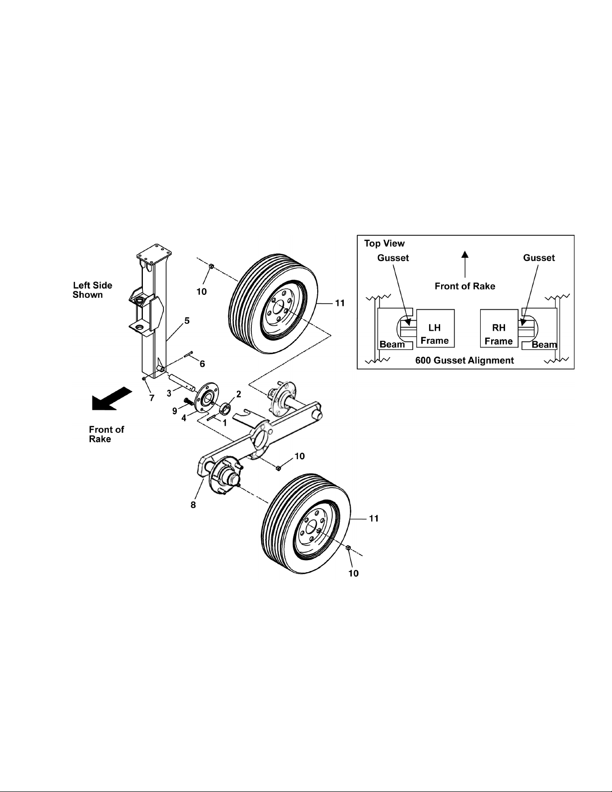
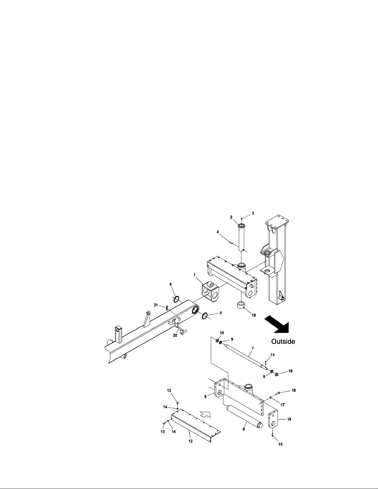
Unless otherwise noted, the standard fastening
procedure is to secure two parts with a cap screw and
lock nut. A part with a mounting slot should be secured
with a plain washer against the slotted surfaces. Lock
nuts are sometimes used to prevent two parts from
separating but still allow one part to move or rotate next
to the other. Attaching hardware, if it will require
installation in the path of material flow, should always
be installed with the head of the screw on the same side
of the part that will be in contact with the material.
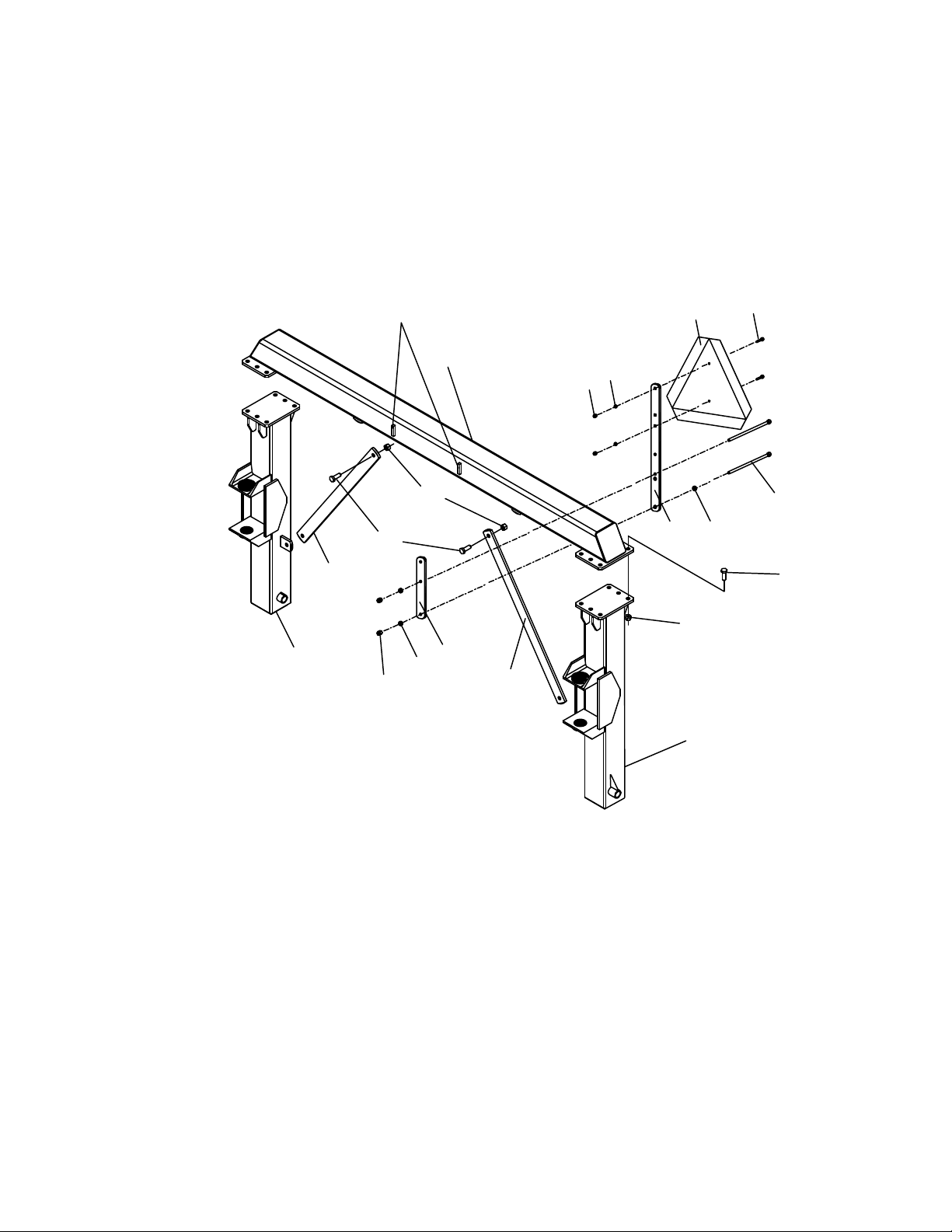
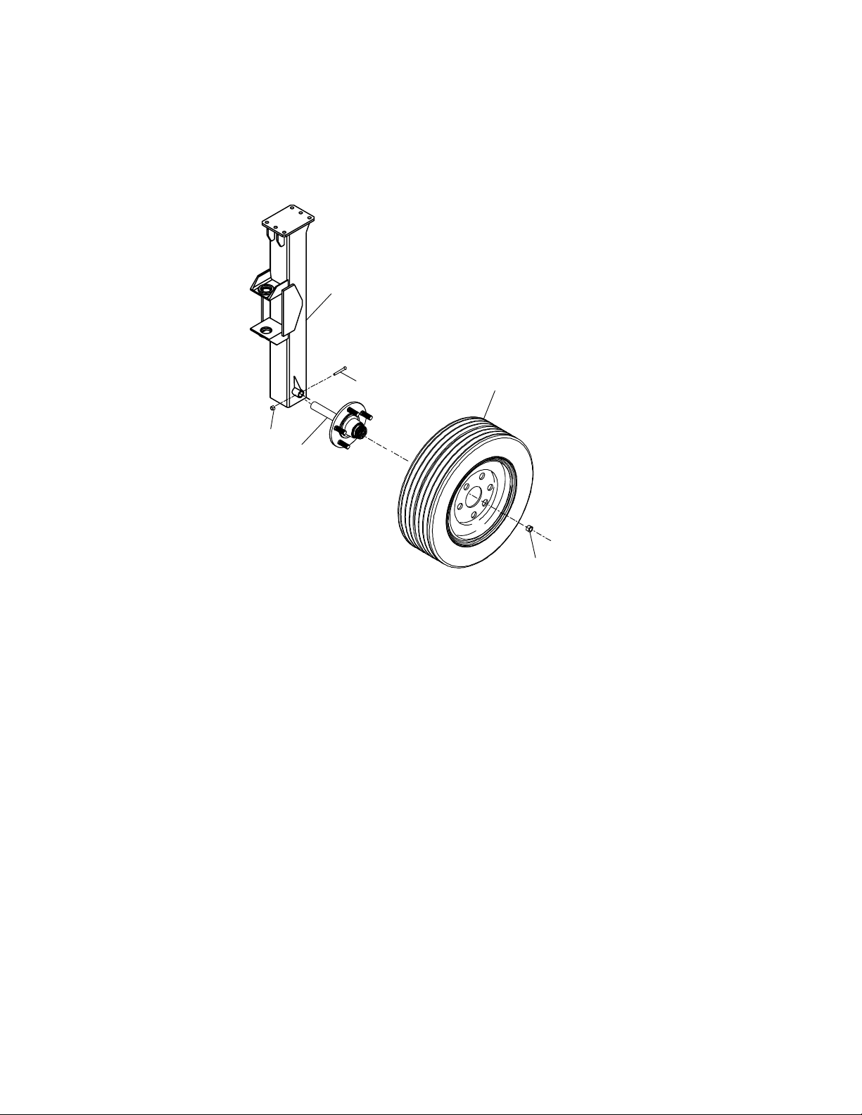
SETUP
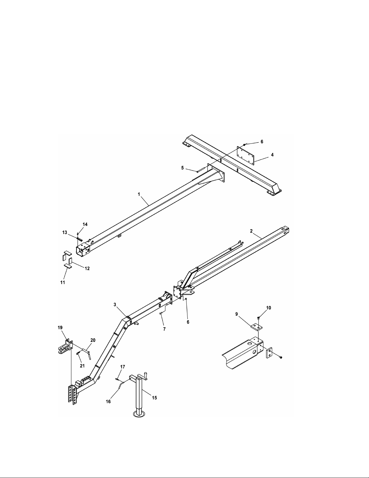
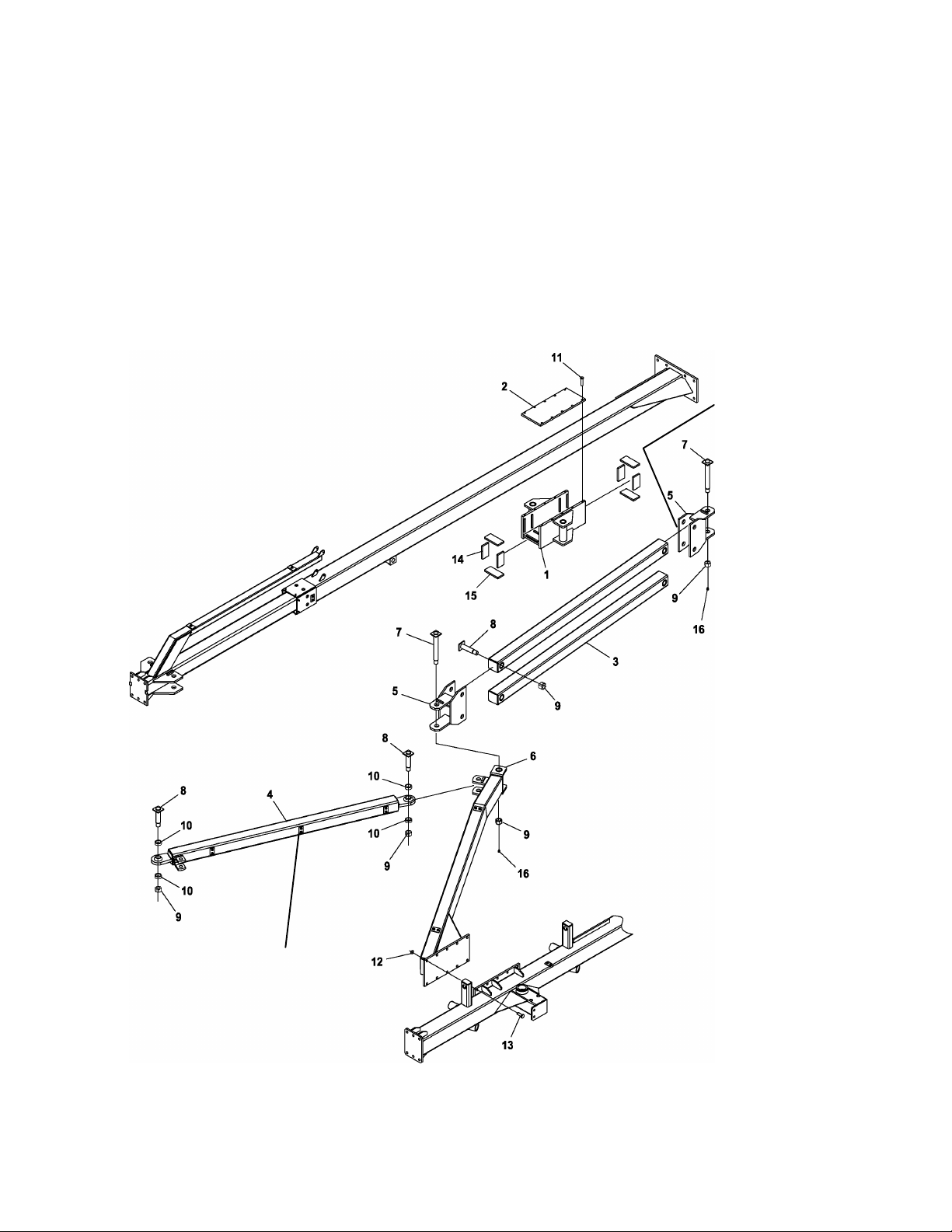
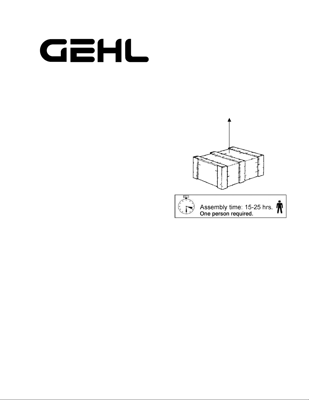
1. Implement is shipped disassembled in wooden
crates. Approximate assembly time is between
15-25 hours, depending on what options are to be
installed. The majority of the fasteners are metric.
Fig. 1
IMPORTANT: Use only metric tools for metric
fasteners.
2. Select an area that has adequate space for parts
layout and machine assembly. Remove all parts
from the crate and lay them out in assembly order
according to Fig. 2.
918203/AP0305 2Printed in U.S.A.
Fig. 2
2, Fig. 3
3, Fig. 3 5, Fig. 4
1, Fig. 3
4, Fig. 3
4, Fig. 8
1, Fig. 8
1, Fig. 7
5, Fig. 10
3, Fig. 10
5, Fig. 10
2, Fig. 11
21, Fig. 6
6, Fig. 6
7, Fig. 6
4, Fig. 10
6, Fig. 10
10, Fig. 12
6RH, Fig. 10
22, Fig. 6
2, Fig. 8 15, Fig. 8
1, Fig. 9
5, Fig. 10
3, Fig. 10
1, Fig. 7
7, Fig. 6
1, Fig. 10
5, Fig. 10
1, Fig. 6
6, Fig. 6
4, Fig. 10
10, Fig. 12
6LH, Fig. 10
6, Fig. 10
2, Fig. 6
1, Fig. 9
6RH, Fig. 7
6LH, Fig. 7
11, 12, Fig. 14
1, Fig. 4 1, Fig. 4
Printed in U.S.A. 3918203/AP0305
REAR FRAME ASSEMBLY (Fig. 3)
1. Assemble the rear member (1) with the key stock facing forward to the right hand wheel support (2) and the left
hand wheel support (3) using the M14 x 40 bolts (6) and the M14 nuts (7) as shown.
2. Install the two supports (4) as shown using the M14 x 40 bolts (6) and the M14 nuts (7).
3. Attach SMV brackets (11, 12) to the rear member (1) using two 3/8 x 6 bolts (13), two 3/8 flat washers (18),
two 3/8 lock washers (15) and two 3/8 hex nuts (14).
4. Attach SMV emblem (16) to the SMV bracket (12) using two 1/4 x 3/4 bolts (17), two 1/4 lock washers (10)
and two 1/4 hex nuts (9).
Fig. 3
1
2
4
4
3
6
7
7
612 18
11
15
14
910
16 17
13
Key stock facing forward
918203/AP0305 4Printed in U.S.A.
SINGLE AXLE FOR REAR FRAME (Fig. 4)
1. Apply grease to spindle (1) and slide into rear frame (2). Secure with M10 x 90 cap screw (3) and M10 locknut
(4).
2. Attach ground wheel (5) to hub (1) with M16 conical lug nuts (6).
3. Repeat steps 1 and 2 on opposite side of rear frame.
Fig. 4 6
5
1
3
4
Left Side
Shown
2
Printed in U.S.A. 5918203/AP0305
TANDEM AXLE FOR REAR FRAME (Fig. 5)
1. Insert spring pin (1) through bushing (2) and pivot shaft (3).
2. Slide support hub (4) onto pivot shaft (3) with flange next to bushing (2).
3. Apply grease to pivot shaft (3) and slide into rear frame (5). Secure with M10 x 90 cap screw (6) and M10 lock
nut (7).
4. Position tandem beam (8) against support hub (4). The gusset on the rear frame (5) must be centered in the cutout
in the tandem beam (8). See 600 Gusset Alignment illustration below.
5. Attach tandem beam (8) to support hub (4) with M16 x 55 cap screws (9) and M16 conical lug nuts (10).
6. Attach two ground wheels (11) to tandem beam (8) with M16 conical lug nuts (10).
7. Repeat steps 1-6 on opposite side of rear frame.
Fig. 5
918203/AP0305 6Printed in U.S.A.
WING FRAME ASSEMBLY (Fig. 6)
1. Using stands (19) that are 30” (762 mm) high, support the frames and connect the rear frame (1), the front frame
(2) and secure using the M14 x 40 bolts (4) and the M14 lock nuts (5).
NOTE: If an optional extension frame, flex frame, center splitter wheel or extra wheel kit is to be
installed, please see the options sections (Figs. 15-20) of this setup manual.
2. Insert the lift rods (6), (7) in their guides on the frame with the bushings (8, 9, 10, 11) and secure them using
the M8 x 50 bolts (12) and the M8 nylon lock nuts (13). Install grease (20) in bushing (10). Bushing (10) should
remain loose and slide freely on the lift tube.
3. Adjust the pivot safety pin (14) to the parking position with the lock pin (15) located in the hole closest to the
front of the machine.
4. Attach the handle knob (17) for the ground pressure adjustment rod using a M12 x 90 bolt (16) and a M12 jam
nut (18). Follow the same assembly procedure for the right hand side of the machine.
5. Attach the decal plate (3) to the back of the left wing frame mount using two M14 x 40 bolts (4) and two M14
lock nuts (5). The amber reflective decal plate is to face forward and this should always be mounted to the most
forward end of the left wing.
NOTE: If an optional extension frame, flex frame or extra ground wheel kit is to be installed, install the
decal plate (3) on the back of the left, front extension mount.
Fig. 6
Printed in U.S.A. 7918203/AP0305
WINDROW ADJUSTMENT ASSEMBLY (Fig. 7)
1. Thread the acme screw (7) half-way into the sliding rail (1) with the hole in the acme screw (7) facing towards
the outside of the machine as shown. Attach the sliding rail (1) to the wing frame as shown. Secure in place by
inserting the sliding rod (8).
2. Attach washer (9), with the grooved side of the washer towards the bearing balls, and bearing (10) to the inside
end (the end without the hole in it) of the acme screw (7). Attach the support adjustment device (6) on to the
acme screw (7) and the sliding rod (8). Attach washer (9) and bearing (10) to the outside end (the end with the
hole in it) of the acme screw (7) and slide the attachment plate (18) on to the acme screw (7) and the sliding
rod (8).
NOTE: Be sure that the end of the acme screw (7) with the hole is located on the outside of the rake
as shown.
3. Secure the attachment plate (18) to the support adjustment device (6) using four M10 washers (17) and four M10
x 40 bolts (16). Install one M8 x 30 bolt (15) in to the bottom of the attachment plate (18) to secure the sliding
rod (8). Install the spring pin (11) half-way through the hole in the outside end of the acme screw (7). Apply
grease to the acme screw (7) and the sliding rod (8).
4. Attach cover plate (12) to the support adjustment device (6) and the attachment plate (18) using twelve M8 wash-
ers (14) and M8 x 16 bolts (13). Repeat stops 10-12 for the other side of the unit.
5. Attach the support adjustment device (6) to the rear frame assembly by using pivot pin (2) and bushing (19) and
secure in place using the spring pin (4). Install grease zerk (3) in to the top of the pivot pin (2).
6. Attach windrow width adjustment handle (20) to the bracket and secure using cotter pin (21).
Fig. 7
918203/AP0305 8Printed in U.S.A.
DRAWBAR ASSEMBLY (Fig. 8)
1. Install the rear drawbar (1) to the rear member with the plate (4) using eight M14 x 160 cap screws (5) and eight
M14 lock nuts (6). Assemble the nylon plates (9) on the sliding drawbar (2) using the eight M8 x 20 cap screws
(10). Lightly grease all the drawbar sliding surfaces (2) and the nylon plates.
2. Insert the sliding drawbar (2) inside the rear drawbar (1) and fit the nylon plates (11, 12) as shown. Secure the
nylon plates in position using the angle plates (13) and eight M8 lock nuts (14).
3. Attach the front drawbar (3) to the sliding drawbar (2) using eight M14 x 40 cap screws (7) and eight M14 lock
nuts (6).
4. Install the hitchjack (15) to the front drawbar (3) using pin (16) and cotter pin (17).
5. Install the bracket (19) to the front drawbar (3) using the two pins (20) and two cotter pins (18).
Fig. 8
Printed in U.S.A. 9918203/AP0305
CASTER WHEEL ASSEMBLY (Fig. 9)
1. Assemble the wheel with hub (6) into the wheel fork (1) using the wheel fork pivot (9), short spacer (7), long
spacer (8) and lock nut (10) as shown.
2. Slide the shaft of the wheel fork assembly (1) up into the wheel support and install the brake plates (5) onto the
brake disk (3) and secure them in place using the spring pin (4). Repeat for the other side.
3. Install grease zerk (11) into the hole on the back side of the pivot on both sides.
Fig. 9
918203/AP0305 10 Printed in U.S.A.
OPENING ARM ASSEMBLY (Fig. 10)
1. Insert the nylon plates (14, 15) inside the slide (1) in the slots properly, long nylon plates on the top and bottom
and the short plates on the sides. Mount the slide (1) on the rear drawbar and attach the cover (2) using the ten
M10 x 30 cap screws (11).
2. Assemble the arm (6) on the wing frame and secure it using ten M12 x 40 (13) and ten M12 lock nuts (12).
3. Assemble the parallel arms (3) with the hinges (5), with the key stock on the hinges (5) towards the middle of
the rake, and secure with the pivots (8) and nuts (9) with the nut end of the pivots (8) toward the outside of the
rake as shown. Mount parallel assembly between the slide (1) the arm (6) and secure using the pivot (7) and the
nut (9). Install grease zerk (16) in the bottom of pin (7). Install the opening arm (4) between the arm (6) and the
front drawbar as shown and secure it using the pivot (8), spacers (10) and nut (9). Repeat the same steps for the
other side.
Fig. 10
Key stock
facing the
middle of
the rake
Direct anchors
for hose clamps
out and forward