Toro 23136 User manual

Form No. 3447-325 Rev D
Concrete Breaker
23136
Betonbrecher
23136
Martillo hidráulico
23136
Brise-béton
23136
Betonbreker
23136
www .T oro.com.
*3447-325*


FormNo.3447-314RevD
ConcreteBreaker
CompactToolCarriers
ModelNo.23136—SerialNo.321000001andUp
Registeratwww.Toro.com.
OriginalInstructions(EN)*3447-314*

WARNING
CALIFORNIA
Proposition65Warning
Useofthisproductmaycauseexposure
tochemicalsknowntotheStateof
Californiatocausecancer,birthdefects,
orotherreproductiveharm.
Introduction
Thisconcretebreakerisintendedtobeusedona
Torocompacttoolcarrier.Itisdesignedprimarily
forbreakingconcrete,asphalt,rock,orbrickduring
renovationjobs.
Readthisinformationcarefullytolearnhowtooperate
andmaintainyourproductproperlyandtoavoid
injuryandproductdamage.Youareresponsiblefor
operatingtheproductproperlyandsafely.
Visitwww.Toro.comforproductsafetyandoperation
trainingmaterials,accessoryinformation,helpnding
adealer,ortoregisteryourproduct.
Wheneveryouneedservice,genuineToroparts,or
additionalinformation,contactanAuthorizedService
DealerorToroCustomerServiceandhavethemodel
andserialnumbersofyourproductready.Themodel
andserialnumbersareprintedonaplatelocatedon
therightsideofthedrivehead.Writethenumbersin
thespaceprovided.
Important:Withyourmobiledevice,youcan
scantheQRcodeontheserialnumberdecal(if
equipped)toaccesswarranty,parts,andother
productinformation.
g360512
Figure1
1.Modelandserialnumberlocation
ModelNo.
SerialNo.
Thismanualidentiespotentialhazardsandhas
safetymessagesidentiedbythesafety-alertsymbol
(Figure2),whichsignalsahazardthatmaycause
seriousinjuryordeathifyoudonotfollowthe
recommendedprecautions.
g000502
Figure2
Safety-alertsymbol
Thismanualuses2wordstohighlightinformation.
Importantcallsattentiontospecialmechanical
informationandNoteemphasizesgeneralinformation
worthyofspecialattention.
©2023—TheToro®Company
8111LyndaleAvenueSouth
Bloomington,MN554202
Contactusatwww.Toro.com.
PrintedintheUSA
AllRightsReserved

Contents
Safety.......................................................................3
GeneralSafety...................................................3
SlopeSafety.......................................................4
ConcreteBreakerSafety....................................4
MaintenanceandStorageSafety........................4
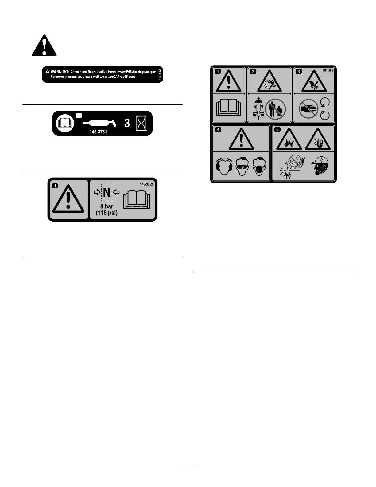
SafetyandInstructionalDecals..........................5
Setup........................................................................6
1InstallingtheBit...............................................6
ProductOverview.....................................................6
Specications....................................................6
Attachments/Accessories...................................6
Operation..................................................................7
InstallingandRemovingtheAttachment.............7
SelectingaT ool..................................................7
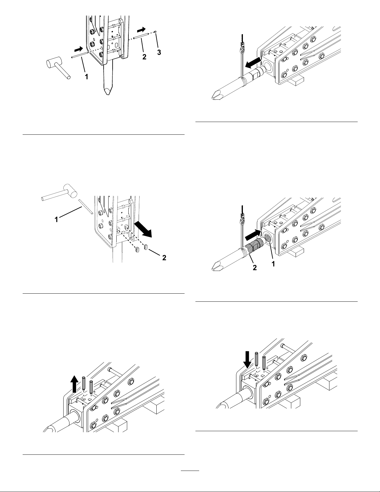
ReplacingtheBit................................................7
TestingtheBreaker.............................................9
BreakingMaterial.............................................10
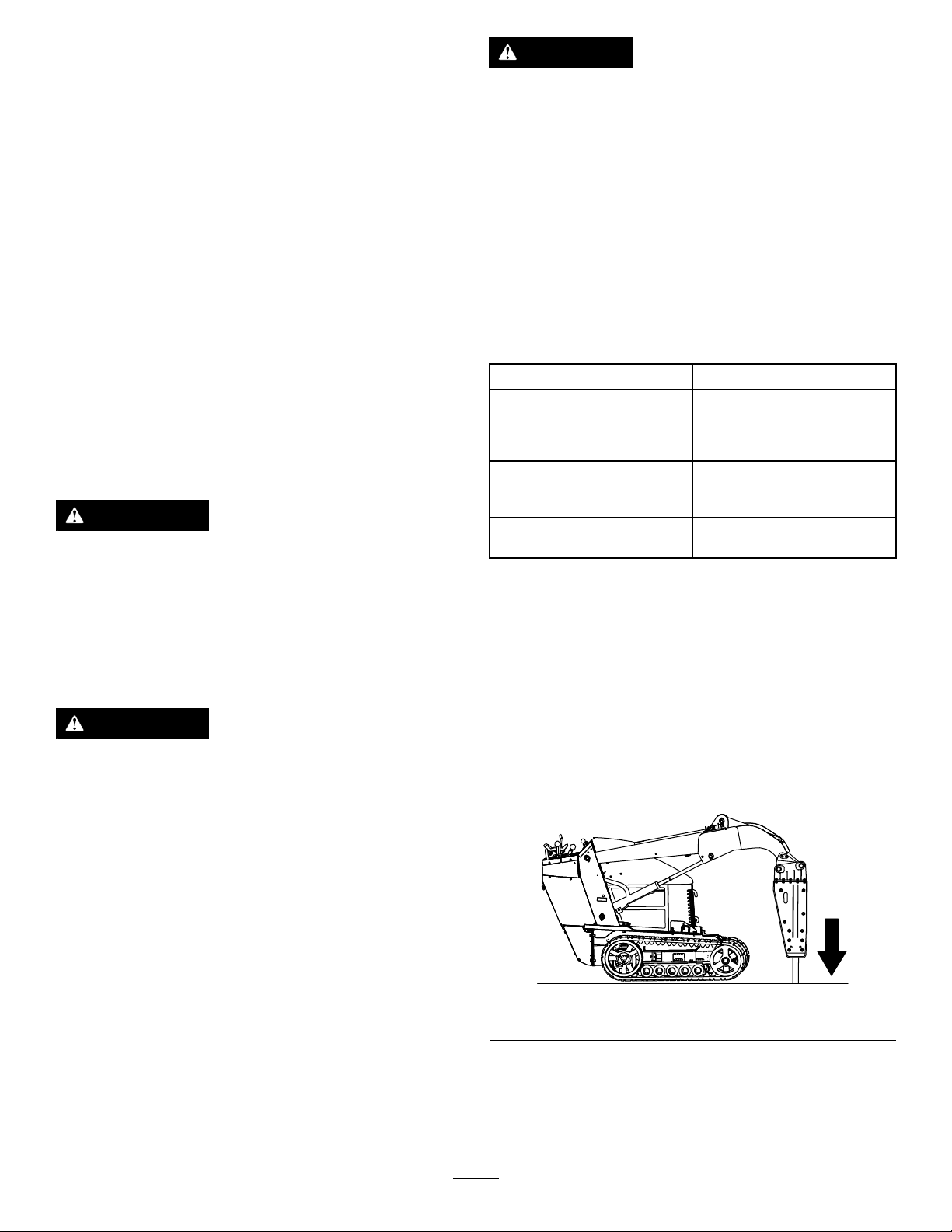
BreakingaVerticalSurface...............................10
TransportPosition............................................10
OperatingTips..................................................11
Maintenance...........................................................12
RecommendedMaintenanceSchedule(s)...........12
GreasingtheBit................................................12
CheckingtheNitrogenCharge..........................13
CheckingtheHydraulicLines...........................13
Storage...................................................................14
StoringtheAttachment.....................................14
Troubleshooting......................................................15
Safety
DANGER
Theremaybeburiedutilitylinesinthework
area.Diggingintothemmaycauseashock
oranexplosion.
Havethepropertyorworkareamarkedfor
buriedlinesanddonotdiginmarkedareas.
Contactyourlocalmarkingserviceorutility
companytohavethepropertymarked(for
example,intheUS,call811orinAustralia,
call1100forthenationwidemarkingservice).
GeneralSafety
Alwaysfollowallsafetyinstructionstoavoidserious
injuryordeath.
•Donottransportanattachmentwiththearms
raised.Alwaystransporttheattachmentcloseto
theground;refertoTransportPosition(page10).
•Havethepropertyorworkareamarkedforburied
linesandotherobjects,anddonotdiginmarked
areas.
•ReadandunderstandthecontentofthisOperator’s
Manualbeforestartingtheengine.
•Useyourfullattentionwhileoperatingthe
machine.Donotengageinanyactivitythat
causesdistractions;otherwise,injuryorproperty
damagemayoccur.
•Neverallowchildrenoruntrainedpeopleto
operatethemachine.
•Keepyourhandsandfeetawayfromthemoving
componentsandattachments.
•Donotoperatethemachinewithouttheguards
andothersafetyprotectivedevicesinplaceand
workingonthemachine.
•Keepbystandersandpetsawayfromthemachine.
•Stopthemachine,shutofftheengine,andremove
thekeybeforeservicing,fueling,orunclogging
themachine.
Improperlyusingormaintainingthismachinecan
resultininjury.Toreducethepotentialforinjury,
complywiththesesafetyinstructionsandalways
payattentiontothesafety-alertsymbol,which
meansCaution,Warning,orDanger—personalsafety
instruction.Failuretocomplywiththeseinstructions
mayresultinpersonalinjuryordeath.
3

SlopeSafety
•Operatethemachineupanddownslopeswith
theheavyendofthemachineuphill.Weight
distributionchangeswithattachments.This
attachmentmakesthefrontofmachinetheheavy
end.
•Keeptheattachmentintheloweredposition
whenonslopes.Raisingtheattachmentona
slopeaffectsthestabilityofthemachine.
•Slopesareamajorfactorrelatedtolossofcontrol
andtip-overaccidents,whichcanresultinsevere
injuryordeath.Operatingthemachineonany
slopeoruneventerrainrequiresextracaution.
•Establishyourownproceduresandrulesfor
operatingonslopes.Theseproceduresmust
includesurveyingthesitetodeterminewhich
slopesaresafeformachineoperation.Always
usecommonsenseandgoodjudgmentwhen
performingthissurvey.
•Slowdownanduseextracareonhillsides.Ground
conditionscanaffectthestabilityofthemachine.
•Avoidstartingorstoppingonaslope.Ifthe
machinelosestraction,proceedslowly,straight
downtheslope.
•Avoidturningonslopes.Ifyoumustturn,turn
slowlyandkeeptheheavyendofthemachine
uphill.
•Keepallmovementsonslopesslowandgradual.
Donotmakesuddenchangesinspeedor
direction.
•Ifyoufeeluneasyoperatingthemachineona
slope,donotdoit.
•Watchforholes,ruts,orbumps,asuneventerrain
couldoverturnthemachine.T allgrasscanhide
obstacles.
•Usecautionwhenoperatingonwetsurfaces.
Reducedtractioncouldcausesliding.
•Evaluatetheareatoensurethatthegroundis
stableenoughtosupportthemachine.
•Usecautionwhenoperatingthemachinenearthe
following:
–Drop-offs
–Ditches
–Embankments
–Bodiesofwater
Themachinecouldsuddenlyrolloverifatrack
goesovertheedgeortheedgecavesin.Maintain
asafedistancebetweenthemachineandany
hazard.
•Donotremoveoraddattachmentsonaslope.
•Donotparkthemachineonahillsideorslope.
ConcreteBreakerSafety
•Wearpersonalprotectiveequipment(PPE)and
appropriateclothing,includingthefollowing:
–Hardhat
–Respiratorordustmask
–Safetyglasses
–Hearingprotection
–Substantial,slip-resistantfootwear
–Longpants
–Shirtwithlongsleevesthataretightatthe
wrists
–Tight-ttinggloveswithoutdrawstringsorloose
cuffs
•Forwheeledtractionunits,usethecounterweight
whenusingtheattachment.
•Keepthetractionunitawayfromtheedgebeing
broken.
•Donotbreakmaterialdirectlyunderthefrontof
thetractionunit.
•Withinthebreakerisachambercontaining
pressurizednitrogen,whichundertheright
circumstancescouldexplode.Donotdisassemble
thebodyofthebreaker.
•Donotattempttochargethecushionchamber
yourself.ContactyourAuthorizedServiceDealer
forcharging.
•Ensurethatthebreakerischargedonlywith
nitrogen.
•Donotshipthechargedbreakerviaairfreight.
MaintenanceandStorage
Safety
•Checkfastenersatfrequentintervalsforproper
tightnesstoensurethattheequipmentisinsafe
operatingcondition.
•RefertothisOperator’sManualforimportant
detailsifyoustoretheattachmentforanextended
periodoftime.
•Maintainorreplacesafetyandinstructionlabels,
asnecessary.
4

SafetyandInstructionalDecals
Safetydecalsandinstructionsareeasilyvisibletotheoperatorandarelocatednearanyarea
ofpotentialdanger.Replaceanydecalthatisdamagedormissing.
decal133-8061
133-8061
decal145-3751
145-3751
1.ReadtheOperator’sManual;greasethemachineevery3
hours.
decal145-3752
145-3752
1.Warning—Maximumpressure8bar(116psi);readthe
Operator’sManual.
decal145-3753
145-3753
1.Warning—readthe
Operator’sManual.
4.Warning—wearhearing,
eye,andrespiratory
protection.
2.Thrownobject
hazard—keepbystanders
away
5.ExplosionandElectric
shockhazard—donot
operatethemachine;call
yourlocalutilitycompany.
3.Cutting/dismemberment
hazardofhand—stay
awayfrommovingparts.
5

Setup
1
InstallingtheBit
NoPartsRequired
Procedure
1.Placetheconcretebreakeronwoodenblocks
withtheretainer-pinplugspointedtowardsthe
ceiling.
2.Removetheretainer-pinplugsfromtheconcrete
breaker.
3.Removetheretainerpins(Figure6).
4.Installthebit;refertoInstallingtheBit(page8).
ProductOverview
Specications
Note:Specicationsanddesignaresubjectto
changewithoutnotice.
Width63cm(24.8inches)
Length130cm(51.2inches)
Height33cm(13.0inches)
Weight176kg(389lb)
Bitworkinglength29cm(11.4inches)
Bitdiameter5cm(2inches)
Impactenergyclass339J(250ft-lb)
Impactrate600to1150bpm
Flowrange20to35Lperminute(5.3to
8.2USgallonsperminute)
Attachments/Accessories
AselectionofT oroapprovedattachmentsand
accessoriesisavailableforusewiththemachine
toenhanceandexpanditscapabilities.Contact
yourAuthorizedServiceDealerorauthorizedT oro
distributororgotowww.T oro.comforalistofall
approvedattachmentsandaccessories.
Toensureoptimumperformanceandcontinuedsafety
certicationofthemachine,useonlygenuineToro
replacementpartsandaccessories.Replacement
partsandaccessoriesmadebyothermanufacturers
couldbedangerous,andsuchusecouldvoidthe
productwarranty.
6

Operation
Important:For300seriestractionunits,ensure
thatyouinstalltheReliefValveKitonyourtraction
unitbeforeusingthebreaker.Failuretoinstallthe
kitmaydamageyourtractionunit.Refertoyour
AuthorizedServiceDealerformoreinformation.
InstallingandRemoving
theAttachment
RefertotheOperator’sManualforthetractionunitfor
theinstallationandremovalprocedure.
Important:Beforeinstallingtheattachment,
positionthemachineonalevelsurface,ensure
thatthemountplatesarefreeofanydirtordebris,
andensurethatthepinsrotatefreely.Ifthepins
donotrotatefreely,greasethem.
Note:Alwaysusethetractionunittoliftandmove
theattachment.
WARNING
Ifyoudonotfullyseatthequick-attach
pinsthroughtheattachmentmountplate,
theattachmentcouldfalloffthemachine,
crushingyouorbystanders.
Ensurethatthequick-attachpinsarefully
seatedintheattachmentmountplate.
WARNING
Hydraulicuidescapingunderpressurecan
penetrateskinandcauseinjury.Fluidinjected
intotheskinmustbesurgicallyremoved
withinafewhoursbyadoctorfamiliarwith
thisformofinjury;otherwise,gangrenemay
result.
•Ensurethatallhydraulic-uidhoses
andlinesareingoodconditionandall
hydraulicconnectionsandttingsaretight
beforeapplyingpressuretothehydraulic
system.
•Keepyourbodyandhandsawayfrom
pinholeleaksornozzlesthateject
high-pressurehydraulicuid.
•Usecardboardorpapertondhydraulic
leaks;neveruseyourhands.
CAUTION
Hydrauliccouplers,hydrauliclines/valves,
andhydraulicuidmaybehot.Ifyoucontact
hotcomponents,youmaybeburned.
•Weargloveswhendisconnectingthe
hydrauliccouplers.
•Allowthemachinetocoolbeforetouching
hydrauliccomponents.
•Donottouchhydraulicuidspills.
SelectingaTool
Usethefollowingtabletochoosethemostsuitable
toolforoperation:
ToolUse
ChiselUseforallearth-moving
duties,excavationsinnarrow
trenches,stratiedsoil,orrock
uptomediumrock.
MoilUsetodemolishrocksand
materials,notstratiedrock,
uptomediumhardness.
AsphaltCutterUsetocutasphaltpaving,
brickwalls,orturf.
ReplacingtheBit
RemovingtheBit
1.Parkthemachineonalevelsurfaceandengage
theparkingbrake(ifapplicable).
2.Raisetheloaderarmsandtiltthebreakerso
thatitisvertical.
3.Lowerthebittothegroundtopushitupintothe
breakeruntilitstops.
g359140
Figure3
4.Shutofftheengineandremovethekey.
5.Installthecylinderlocks.
6.Useahammerandthebit-pinremoverto
removethestopperplugandstopperpin.
7

g358958
Figure4
1.Bit-pinremover3.Stopperplug
2.Stopperpin
7.Fromtheoppositesideoftheretainer-pinplugs,
useahammerandthebit-pinremovertoremove
the2retainer-pinplugs.
Note:Donotremovetheretainerpins;
otherwisethebitmayfallout.
g359829
Figure5
1.Bit-pinremover2.Retainer-pinplug(2)
8.Removetheloaderarmcylinderlocks.
9.Lowertheloaderarmsandplacethebreaker
onwoodenblockswiththeretainer-pinplugs
pointedtowardstheceiling.
10.Shutofftheengineandremovethekey.
11.Usethebit-pinremoverfromunderneaththe
retainerpinstoremovethepins.
g429684
Figure6
12.Removethebit.
g429706
Figure7
InstallingtheBit
1.Ensurethattheconcretebreakerrestsonthe
ground.
2.Greasethebitandinsideofthebitbushing.
Note:Donotapplygreasetothesmallshaftat
theendofthebit.
g429754
Figure8
1.Bitbushing2.Bit
3.Insertthebitintothebreakerhousing,aligning
thenotchesinthebittotheretainerpinopenings.
4.Installthe2retainingpins.
g429705
Figure9
5.Useahammerandbit-pinremovertoinstallthe
stopperpinandstopperplug.
8

Important:Ensurethatthestopperplugis
fullyinsertedinthehousingasshownin
Figure11.
g429755
Figure10
1.Stopperpin3.Pinremover
2.Stopperplug
g358957
Figure11
1.Stopperpin2.Stopperplug
6.Installthe2retainer-pinplugs,aligningtheslot
intheplugswiththestopperpin.
g359804
Figure12
1.Retainer-pinplug(2)
7.Greasethebit;refertoGreasingtheBit(page
12).
TestingtheBreaker
Important:Afterinstallingthebreakerona
machine,especiallyafterstorage,alwaystestit
beforeyoubreakmaterialtoreleaseairfromthe
oilcircuit.Usingthebreakersuddenlywithout
releasingtheairbreakstheoillmandcauses
thebreakertoseize.
1.Parkthemachineonalevelsurfaceandengage
theparkingbrake(ifapplicable).
2.Raisetheloaderarmsandtiltthebreakerso
thatitisvertical.Ensurethatthebitdoesnot
touchtheground.
g359139
Figure13
3.Slowlyengagetheforwardhydraulicsuntilthe
breakerpistonrises,thenslowlyreversethe
hydraulicsbeforethepistonimpacts.
Important:Donotallowthepistonto
impact.
4.Refertothetablefortestingtimesforthe2
stages.
Important:Donotallowthepistontoimpact
duringtheairremovalandsealrecovery
time.
12
Airremovaland
sealrecoverytimePreparationtime
Newbreaker
Afterhosesare
connected,no
repairs
15minutes
Afterrepairsto
breaker20minutes
Operatethe
machinefor
10minutesat
50%throttle
then
20minutesat
70%throttle
9

BreakingMaterial
Important:Continuouslyimpactingthesame
locationforlongperiodsoftimecreateshigh
temperaturesatthetipofthebit.Thiscouldcause
thebittoloseitstemperandmushroomunder
impact,destroyingthebit.
1.Adjustthethrottleforyourmachineas
appropriateforbreakingmaterial:
•For300-seriesmachines,usefullthrottle
(maximumenginespeed),uselowrange
(turtleposition)onthespeed-selector
lever,andadjusttheow-dividervalveto
approximatelythe10o’clockposition.
•Fore-Dingomachines,changethe
attachmentmodetoHammerMode.
•ForTX-seriesmachines,use3/4throttle.
2.Placethebreakerbitwithin15to46cm(6to
18inches)fromtheedgeofthematerialtobe
broken,ata90-degreeangle.
g359138
Figure14
3.Applydownwardpressurewiththeloaderarms
untilthefrontofthetractionunitraisesoffthe
groundabout5cm(2inches).
Note:Donotengagethebreakerunlessthe
bitisonthegroundanddownwardpressureis
applied.
Important:Ensurethatthehydraulic
cylindershaveatleast5cm(2inches)of
stroke;donotusetheconcretebreakerwith
thehydrauliccylindersfullyextended.
4.Engagethebreakerandmaintainthedownward
pressureasthebitworksitswayintothe
materialbeingbroken.
5.Whenthematerialisbroken,immediately
disengagethehydraulicstostopstrikingthe
material.
BreakingaVerticalSurface
1.Positionthebitontheverticalsurfaceinthe
samemannerasyouwouldpositionitona
horizontalsurface.
2.Maintainpressureonthebitbydrivingthe
tractionunitforwardintotheverticalsurface
whileoperatingthebreaker.
3.Periodicallylowerthebreakertoavertical
positiontoallowdebristhatmayhavecollected
inthebreakertofallout.
TransportPosition
Whentransportingtheattachment,keepitasclose
tothegroundaspossible,nomorethan15cm(6
inches)abovetheground.Tiltitrearward.
g359749
Figure15
1.Nomorethan15cm(6
inches)abovetheground
2.Tilttheattachment
rearward.
10

OperatingTips
•Ifthebitispositionedtoofarfromtheedgeofthe
material,thematerialmayabsorbtheenergyand
notbreak.
•Ifthematerialdoesnotbreakafter1minute,stop
thebreakerandmovethebittoadifferentlocation.
•Donotbindthebitinthematerialbeing
cut,otherwisethebitmaybendorwearout
prematurely.Ensurethatallforceappliedtothe
breakerisinlinewiththebit,notsidetosideor
fronttoback.Thisrequiresfrequentadjustments
inthepositioningofthetractionunit.
•Listentothesoundofthebreakerwhenis
operating.Thesoundchangeswhendownward
pressuredecreases.Ifthedownwardpressure
fromtheunitistooweak,youwillhearmetallic
strokesfromthehammerasitincorrectlystrikes
thebit.
•Excessivedownwardpressureproducesstrong
vibrationsintheunit.
•Manymaterialsdonotbreakwellwithcontinuous
hammeringinonelocation.Eachtimethatthe
breakerpenetratesthematerialwithoutbreaking
it,moveittoanewlocationinalineparallelto
theedgeofthematerial,about7.6cm(3inches)
fromtheprevioushole.Thisscoresthematerial
and,ifdonerepeatedly,breaksoffalargepiece
ofthematerial.
g359750
Figure16
•Ifyouarebreakingrebar-reinforcedconcrete,use
achiselbitinthebreakertocutthroughtherebars
intheconcrete.Youcanalsocuttherebarwith
atorch.
•Toimprovethelifeofthebreaker:
–Ensurethatthehydrauliccylindershaveat
least5cm(2inches)ofstroke;donotusethe
concretebreakerwiththehydrauliccylinders
fullyextended.
–Neverprywiththebitofthebreaker.
–Avoidhittingmaterialabruptlywiththebit.
–Donotusethebreakertoliftormovematerial.
–Donotoperatethebreakerunderwater;only
allowthebitintowater.
11

Maintenance
CAUTION
Ifyouleavethekeyintheignitionswitch,someonecouldaccidentlystarttheengineand
seriouslyinjureyouorotherbystanders.
Removethekeyfromtheignitionbeforeyoudoanymaintenance.
RecommendedMaintenanceSchedule(s)
MaintenanceService
IntervalMaintenanceProcedure
Beforeeachuseordaily
•Greasethebit.(Greaseevery3hoursofoperationandaftereverywashing.)
•Checkthehydrauliclinesforleaks,loosettings,kinkedlines,loosemounting
supports,wear,weather,andchemicaldeterioration.
•Inspectandtightenallfasteners.
•Inspectthemountingpins,holes,bitbushing,andretainerpinsforloosenessor
wear.Reseatorreplaceasnecessary.
Every40hours•Measurethebitlengthwhenpressedintothebitholder.Replacethebitifthe
measuredlengthislessthan200mm(7.8inches).
Every100hours•Checkthenitrogenchargeintheaccumulator.
Beforestorage•Paintchippedsurfaces.
GreasingtheBit
ServiceInterval:Beforeeachuseordaily—Grease
thebit.(Greaseevery3hoursof
operationandaftereverywashing.)
Greasetype:Chiselpaste
1.Parkthemachineonalevelsurfaceandengage
theparkingbrake(ifapplicable).
2.Tiltthebreakersothatitisverticalandlowerit
tothegroundtopushthebitupintothebreaker
untilitstops.
Important:Ifyoudonotpushthebitupinto
thebreakerbeforegreasing,greasemayll
thespacebetweenthetopofthebitandthe
breakerpiston.Thiscausesthepistonto
pressurizethegreaseanddamagetheseal
whenyounextusethebreaker.
3.Shutofftheengineandremovethekey.
4.Cleanthegreasettingwitharag.
5.Connectagreaseguntothetting.
g359783
Figure17
6.Pumpgreaseintothettinguntileithergrease
beginstooozeoutofthelowerbushingand
retainingpinorpumpingthegreasegun
becomesdifcult.
7.Wipeupanyexcessgrease.
12

CheckingtheNitrogen
Charge
ServiceInterval:Every100hours
WARNING
Withinthebreakerisachambercontaining
pressurizednitrogen,whichundertheright
circumstancescouldexplode,injuringor
killingyouorbystanders.
•Donottakeapartthebodyofthebreaker.
•Donotattempttochargethechamber
yourself.Alwaystakethebreakertoan
AuthorizedServiceDealerforcharging.
•Ensurethatthebreakerischargedonly
withnitrogen.Othergasescanexplode.
•Donotshipthechargedbreakerviaair
freight.
Insidethebreakerisanaccumulator,achamberof
pressurizednitrogen.Afterseveralhoursofusethe
pressuremaydecrease,reducingtheperformance
ofthebreaker.
Strongvibrationsintheauxiliaryhydraulichosesarea
signthepressureisdroppinginthechamber.Ifthis
shouldhappen,bringthebreakertoyourAuthorized
ServiceDealertobecharged.
Nitrogengaspressure:8bar(116psi)
1.Parkthemachineonalevelsurface,engage
theparkingbrake(ifapplicable),andlowerthe
breakerontheground.
2.Shutofftheengineandremovethekey.
3.Removethegas-valveplugfromthecylinder
cover.
g359809
Figure18
1.Gasvalve3.Gas-valveplug
2.Pressuregauge
4.Insertapressuregaugeintothegasvalveand
measureit.
5.Ifitislow,contactyourAuthorizedService
Dealertochargeit.
CheckingtheHydraulic
Lines
ServiceInterval:Beforeeachuseordaily
WARNING
Hydraulicuidescapingunderpressurecan
penetrateskinandcauseinjury.Fluidinjected
intotheskinmustbesurgicallyremoved
withinafewhoursbyadoctorfamiliarwith
thisformofinjury;otherwise,gangrenemay
result.
•Keepyourbodyandhandsawayfrom
pinholeleaksornozzlesthateject
high-pressurehydraulicuid.
•Usecardboardorpapertondhydraulic
leaks;neveruseyourhands.
13

Storage
StoringtheAttachment
1.Parkthemachineonalevelsurfaceandengage
theparkingbrake(ifapplicable).
2.Placethebreakeron2piecesofwoodsothat
thecylindersideishigherthanthechiselholder
side.
g359808
Figure19
3.Removetheattachmentfromthemachine.
4.Washtheattachmentwithmilddetergentand
watertoremovedirtandgrime.
5.Checkandtightenallbolts,nuts,andscrews.
Repairorreplaceanydamagedorwornparts.
6.Paintallscratchedorbaremetalsurfaces.Paint
isavailablefromyourAuthorizedServiceDealer.
7.Removethehexplugandsprayanti-rustspray
intothepistonarea.Installthehexplug.
g359806
Figure20
1.Hexplug
8.Iftheattachmentwillbestoredformorethan
30days,releasethegaspressurefromthe
attachment:
A.Removethebit;refertoRemovingtheBit
(page7)
B.Releasethenitrogengasfromthecylinder
coverthroughthegasvalve.
g359805
Figure21
1.Gasvalve
C.Placeadrainpanunderthehosesand
loosentheplugs.
g359807
Figure22
1.Hoseplug2.Rod
D.Insertarodintothepiston,andgentlypush
itinusingahammer.
Note:Thisreleasesanyexcessnitrogen
gasfromthecushionchamber.
E.Tightenthehoseplugs.
F.Greasethebitandinstallit;refertoInstalling
theBit(page8).
9.Storethebreakerinaclean,drygarageor
storagearea.Coverittoprotectitandkeepit
clean.
10.Whenremovingthebreakerfromstorage,
replacethenitrogengasbeforeoperation;
contactyourAuthorizedServiceDealer.
14

Troubleshooting
ProblemPossibleCauseCorrectiveAction
1.Anseal,O-ring,orbackupringisworn
ordamaged.
1.ContactyourAuthorizedService
Dealer.
2.Thepistonorcylinderhasseized.2.ContactyourAuthorizedService
Dealer.
Hydraulicuidisleaking.
3.Thetie-rodnut,chokeplug,orhose
adapterisloose.
3.Tightentheloosepart.
1.AnO-ring,piston,orsealiswornor
damaged.
1.ContactyourAuthorizedService
Dealer.
Morethan10bar(145psi)ofnitrogengas
leaksevery100hours.
2.Thepistonorcylinderhasseized.2.ContactyourAuthorizedService
Dealer.
1.Thehydraulic-uidtemperatureistoo
low.
1.Warmupthebreaker.
2.Thenitrogengaspressureinthe
chamberistoohigh.
2.Releasegaspressuretothecorrect
level.
3.Thestopvalveisclosed.3.Openthestopvalve.
4.Thepressuresettingforthereliefvalve
istoolow.
4.ContactyourAuthorizedService
Dealer.
5.Thehydraulicpumpisperforming
poorly.
5.ContactyourAuthorizedService
Dealer.
6.Thereisnotenoughdownward
pressureonthebit.
6.Applymoredownwardpressuretothe
bit.
Thebreakerdoesnotimpact.
7.Thereisanobstructioninahydraulic
hose.
7.Removetheobstructionorreplacethe
hose.
1.Thecontrolvalve,piston,orcylinder
hasseized.
1.ContactyourAuthorizedService
Dealer.
2.Thepressuresettingforthereliefvalve
istoolow.
2.ContactyourAuthorizedService
Dealer.
3.Thehydraulicpumpisperforming
poorly.
3.ContactyourAuthorizedService
Dealer.
4.Thereisnotenoughdownward
pressureonthebit.
4.Applymoredownwardpressuretothe
bit.
Thebreakerimpactserratically.
5.Thenitrogengaspressureinthe
chamberistoohigh.
5.Releasegaspressuretothecorrect
level.
Thebreakerlackspower.1.Thenitrogengaspressureinthe
chamberistoolow.
1.ContactyourAuthorizedService
Dealer.
15

Notes:

Notes:

DeclarationofIncorporation
TheT oroCompany,8111LyndaleAve.South,Bloomington,MN,USAdeclaresthatthefollowingunit(s)
conform(s)tothedirectiveslisted,wheninstalledinaccordancewiththeaccompanyinginstructionsontocertain
ToromodelsasindicatedontherelevantDeclarationsofConformity.
1
RelevanttechnicaldocumentationhasbeencompiledasrequiredperPartBofAnnexVIIof2006/42/EC.
Wewillundertaketotransmit,inresponsetorequestsbynationalauthorities,relevantinformationonthispartly
completedmachinery.Themethodoftransmissionshallbeelectronictransmittal.
ThismachineryshallnotbeputintoserviceuntilincorporatedintoapprovedT oromodelsasindicatedonthe
associatedDeclarationofConformityandinaccordancewithallinstructions,wherebyitcanbedeclaredin
conformitywithallrelevantDirectives.
Certied:AuthorizedRepresentative:
MarcelDutrieux
ManagerEuropeanProductIntegrity
ToroEuropeNV
Nijverheidsstraat5
2260Oevel
Belgium
ChadMoe
Sr.EngineeringManager
8111LyndaleAve.South
Bloomington,MN55420,USA
May6,2022
Table of contents
Languages:
Other Toro Construction Equipment manuals

Toro
Toro MMX-658H-S User manual

Toro
Toro 22910 User manual

Toro
Toro VR-2650 User manual

Toro
Toro 60213 60216 User manual

Toro
Toro MM Series User manual

Toro
Toro TRX-16 User manual

Toro
Toro TX 427 Installation and operating manual

Toro
Toro MMX-650E-S User manual

Toro
Toro MMXD-958H-S User manual

Toro
Toro 68141 User manual
Popular Construction Equipment manuals by other brands

boplan
boplan FLEX IMPACT FLIP 120M Installation sheet

MQ Multiquip
MQ Multiquip Mikasa MVC-88GE Operation and parts manual

BN Products
BN Products BNHC-20 Operation manual

Yale
Yale SHAW-BOX YK Series Assembly & instruction manual

HADEF
HADEF 320/01 Installation, Operating and Maintenance Instructions for the Installer and the User

Donati
Donati GBA Series instructions