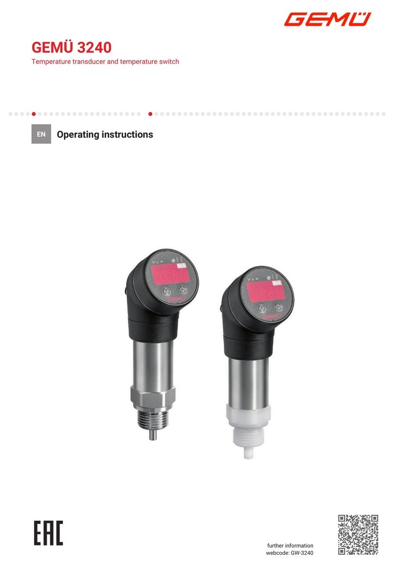
GEM 3220 Assembly instructions

3220
3220
Measurement device
Two-wire measuring transducer
Temperature transducer
GB INSTALLATION, OPERATING AND
MAINTENANCE INSTRUCTIONS
Zwei-Leiter-Messumformer
Messgerät
Temperatur Messumformer
DE ORIGINAL EINBAU- UND MONTAGEANLEITUNG

2 / 24
3220
Inhaltsverzeichnis
1 Allgemeine Hinweise 2
2 Allgemeine Sicherheitshinweise 2
2.1 Hinweise für Service-
und Bedienpersonal 3
2.2 Warnhinweise 3
2.3 Verwendete Symbole 4
3 Vorgesehener Einsatzbereich 4
4 Auslieferungszustand 4
5 Technische Daten 5
6 Bestelldaten 6
7 Herstellerangaben 7
7.1 Transport 7
7.2 Lieferung und Leistung 7
7.3 Lagerung 7
7.4 Benötigtes Werkzeug 7
8 Funktionsbeschreibung 7
9 Mechanischer Anbau 8
10 Elektrischer Anschluss 8
11 Schaltbilder 9
11.1 Schaltbild Messgerät
(Code 610, 620, 630) 9
11.2 Schaltbild Zwei-Leiter-
Messumformer (Code 600) 9
12 Anschlusspläne 10
12.1 Anschlussplan Zwei-Leiter-
Messumformer (Code 600) 10
12.2 Anschlussplan Messgerät mit
Stromausgang (Code 610, 620) 10
12.3 Anschlussplan Messgerät mit
Relaisausgang (Code 630) 10
13 Maße 10
13.1 Maße Zwei-Leiter-
Messumformer (Code 600) 10
13.2 Maße Messgerät
(Code 610, 620, 630) 11
14 Entsorgung 11
15 Rücksendung 11
16 Hinweise 11
1 Allgemeine Hinweise
Voraussetzungen für die einwandfreie
Funktion des Geräts:
Sachgerechter Transport und Lagerung
Installation und Inbetriebnahme durch
eingewiesenes Fachpersonal
Bedienung gemäß dieser Einbau- und
Montageanleitung
Ordnungsgemäße Instandhaltung
Korrekte Montage, Bedienung und Wartung
oder Reparatur gewährleisten einen
störungsfreien Betrieb des Geräts.
Beschreibungen und
Instruktionen beziehen sich auf
Standardausführungen. Für
Sonderausführungen, die in dieser
Einbau- und Montageanleitung
nicht beschrieben sind, gelten die
grundsätzlichen Angaben in dieser
Einbau- und Montageanleitung in
Verbindung mit einer zusätzlichen
Sonderdokumentation.
Alle Rechte wie Urheberrechte
oder gewerbliche Schutzrechte
werden ausdrücklich vorbehalten.
2 Allgemeine
Sicherheitshinweise
Die Sicherheitshinweise berücksichtigen
nicht:
Zufälligkeiten und Ereignisse, die bei
Montage, Betrieb und Wartung auftreten
können.
die ortsbezogenen
Sicherheitsbestimmungen, für
deren Einhaltung – auch seitens des
hinzugezogenen Montagepersonals –
der Betreiber verantwortlich ist.

3 / 24 3220
2.1 Hinweise für Service-
und Bedienpersonal
Die Einbau- und Montageanleitung enthält
grundlegende Sicherheitshinweise, die bei
Inbetriebnahme, Betrieb und Wartung zu
beachten sind. Nichtbeachtung kann zur
Folge haben:
Gefährdung von Personen durch
elektrische, mechanische und chemische
Einwirkungen.
Gefährdung von Anlagen in der
Umgebung.
Versagen wichtiger Funktionen.
Gefährdung der Umwelt durch Austreten
gefährlicher Stoffe bei Leckage.
Vor Inbetriebnahme:
GEinbau- und Montageanleitung lesen.
GMontage- und Betriebspersonal
ausreichend schulen.
GSicherstellen, dass der Inhalt der Einbau-
und Montageanleitung vom zuständigen
Personal vollständig verstanden wird.
GVerantwortungs- und
Zuständigkeitsbereiche regeln.
Bei Betrieb:
GEinbau- und Montageanleitung am
Einsatzort verfügbar halten.
GSicherheitshinweise beachten.
GNur entsprechend der Leistungsdaten
betreiben.
GWartungsarbeiten bzw. Reparaturen,
die nicht in der Einbau- und
Montageanleitung beschrieben sind
dürfen nicht ohne vorherige Abstimmung
mit dem Hersteller durchgeführt werden.
GEFAHR
Sicherheitsdatenblätter bzw. die für
die verwendeten Medien geltenden
Sicherheitsvorschriften unbedingt
beachten!
Bei Unklarheiten:
Bei nächstgelegener GEMÜ-
Verkaufsniederlassung nachfragen.
2.2 Warnhinweise
Warnhinweise sind, soweit möglich, nach
folgendem Schema gegliedert:
SIGNALWORT
Art und Quelle der Gefahr
®Mögliche Folgen bei Nichtbeachtung.
GMaßnahmen zur Vermeidung der
Gefahr.
Warnhinweise sind dabei immer mit
einem Signalwort und teilweise auch
mit einem gefahrenspezifischen Symbol
gekennzeichnet.
Folgende Signalwörter bzw.
Gefährdungsstufen werden eingesetzt:
GEFAHR
Unmittelbare Gefahr!
®Bei Nichtbeachtung sind Tod oder
schwerste Verletzungen die Folge.
WARNUNG
Möglicherweise gefährliche Situation!
®Bei Nichtbeachtung drohen schwerste
Verletzungen oder Tod.
VORSICHT
Möglicherweise gefährliche Situation!
®Bei Nichtbeachtung drohen mittlere bis
leichte Verletzungen.
VORSICHT (OHNE SYMBOL)
Möglicherweise gefährliche Situation!
®Bei Nichtbeachtung drohen
Sachschäden.

4 / 24
3220
2.3 Verwendete Symbole
Hand: Beschreibt allgemeine
Hinweise und Empfehlungen.
GPunkt: Beschreibt auszuführende
Tätigkeiten.
®Pfeil: Beschreibt Reaktion(en) auf
Tätigkeiten.
Aufzählungszeichen
3 Vorgesehener Einsatzbereich
Der GEMÜ Temperatur Messumformer
3220 ist für den Einbau in eine Wandung
konzipiert.
Das Gerät darf nur gemäß den
technischen Daten eingesetzt werden
(siehe Kapitel 5 "Technische Daten").
Schrauben und Kunststoffteile am Gerät
nicht lackieren!
WARNUNG
Das Gerät nur bestimmungsgemäß
einsetzen!
®Sonst erlischt Herstellerhaftung und
Gewährleistungsanspruch.
GDas Gerät ausschließlich entsprechend
den in der Vertragsdokumentation
und Einbau- und Montageanleitung
festgelegten Betriebsbedingungen
verwenden.
GDas Gerät darf nicht in
explosionsgefährdeten Zonen
verwendet werden.
4 Auslieferungszustand
Das Gerät wird als separat verpacktes
Bauteil ausgeliefert.

5 / 24 3220
5 Technische Daten
Umgebungsbedingungen
Zulässige
Umgebungstemperatur -10 ... 50 °C
Zulässige Messstofftemperatur
bei Maximaldruck -10 ... 60 °C
Zulässiger Betriebsdruck ≤10 bar
Lagerungstemperatur -20 ... 60 °C
Störfestigkeit 350 A/m ind.
Anschlüsse
Elektrischer Anschluss Gerätestecker nach DIN EN
175301-803 Form A
Messstoffanschluss G 1/2 nach DIN 3852
G 3/4 nach DIN 3852
Werkstoffe
Messstoffbenetzte Teile DIN 50100
Anschlussstück PVDF
Sensor Keramik 610
Dichtung FPM
Gehäuse ABS
Gehäusedeckel Messgerät PMMA
Allgemeines
Gehäuseschutzart IP 65
Gebrauchslage beliebig
Montageart Montage über Messstoffanschluss
max. Drehmoment 20 Nm
Masse Zwei-Leiter-
Messumformer ca. 155 g
Messgerät ca. 285 g
Weitere Ausführungsarten auf Anfrage
Eingangskenngrößen
Messspanne 0 ... 100 °C
Ausgangskenngrößen
Zwei-Leiter-Messumformer
Signalart 4 - 20 mA
Kennlinie linear
Kennlinienübereinstimmung ± 0,5 % von Messspanne
Bürde siehe Kennlinie
Messgerät mit Stromausgang
Signalart 0/4 - 20 mA
Kennlinie linear
Kennlinienübereinstimmung ± 0,5 % von Messspanne
Bürde ≤750 Ω
Messgerät mit Relaisausgang
Schaltleistung 125V / 2 A / 60 W
Schaltpunkte Min-Relais einstellbar
von 0 - 100 %
Max-Relais einstellbar
von 0 - 100 %
Hysterese Relais ± 1% von Messspanne
Optische Anzeige
Art LC-Display 3 1/2 stellig
(Format 199.9)
Einheiten °C, °F
Funktionen Messwertanzeige
(über Schalter wählbar) Schaltpunkt MIN-Relais
Schaltpunkt MAX-Relais
Genauigkeit ± 0,5 % von Messspanne
± 1 Digit
Hilfsenergie
Zwei-Leiter-Messumformer 15 - 35 V DC
Messgerät 24 V DC (+10 %, -15 %)
Speisespannungseinfluss ≤0,1 % von Messspanne
Druck / Temperatur-Zuordnung für Kunststoff
Temperatur in °C -20 -10 ±0 5 10 20 25 30 40 50 60 70 80 90 100
Werkstoffzulässiger Betriebsdruck [bar]
PVDF Code 20 - 10,0 10,0 10,0 10,0 10,0 10,0 9,0 8,0 7,1 6,3 5,4 4,7 3,6 2,5
Bürde [Ohm]
Versorgungsspannung [V/DC]
Kennlinie
0 500 1000
15
20
25
30
35

6 / 24
3220
6 Bestelldaten
Bestellbeispiel 3220 G2 R 9B 20 B0 C 620 020
Typ 3220
Anschlussgröße G2
Anschlussnorm (Code) R
Anschlussart (Code) 9B
Werkstoff / Anschlussstück (Code) 20
Sensorwerkstoff (Code) B0
Genauigkeitsklasse (Code) C
Messumformer (Code) 620
Messbereich (Code) 020
Genauigkeitsklasse Code
± 0,5 % C
Messumformer Code
2-Leiter-Messumformer 600
Messgerät mit Display und Stromausgang 0 - 20 mA 610
Messgerät mit Display und Stromausgang 4 - 20 mA 620
Messgerät mit Display und Relaisausgang 630
Messbereich Code
0 ... 100 °C 020
32 ... 194 °F 021
-20 ... 80 °C 022
-4 ... 176 °F 023
Anschlussgröße Code
1/2” G2
3/4” G3
SensorwerkstoffCode
Keramik 610 B0
Keramiksensor PVDF ummantelt 20
Anschlussform Code
Rückseitig R
Anschlussnorm Code
Nach DIN 3852 9B
Werkstoff/ Anschlussstück Code
PVDF 20

7 / 24 3220
7 Herstellerangaben
7.1 Transport
GDas Gerät nur auf geeignetem Lademittel
transportieren, nicht stürzen, vorsichtig
handhaben.
GVerpackungsmaterial entsprechend
den Entsorgungsvorschriften /
Umweltschutzbestimmungen entsorgen.
7.2 Lieferung und Leistung
GWare unverzüglich bei Erhalt auf
Vollständigkeit und Unversehrtheit
überprüfen.
GLieferumfang aus Versandpapieren,
Ausführung aus Bestellnummer
ersichtlich.
GDas Gerät wird im Werk auf Funktion
geprüft.
7.3 Lagerung
GDas Gerät staubgeschützt und trocken in
Originalverpackung lagern.
GUV-Strahlung und direkte
Sonneneinstrahlung vermeiden.
GLagertemperatur: siehe Kapitel 5
"Technische Daten".
GLösungsmittel, Chemikalien, Säuren,
Kraftstoffe u.ä. dürfen nicht mit den
Geräten und deren Ersatzteilen in einem
Raum gelagert werden.
7.4 Benötigtes Werkzeug
GBenötigtes Werkzeug für Einbau und
Montage ist nicht im Lieferumfang
enthalten.
GPassendes, funktionsfähiges und
sicheres Werkzeug benutzen.
8 Funktionsbeschreibung
Der Temperatur-Messumformer GEMÜ 3220
wandelt die physikalische Größe Temperatur
proportional in ein elektrisches Signal um.
Der Prozessanschluss ist standardmäßig
mit Außengewinden nach DIN 3852 in
den Größen G 1/2 und G 3/4 ausgeführt.
Der elektrische Anschluss erfolgt mit einer
Gerätesteckdose nach DIN EN 175301-803
Form A. Die Einbaulage ist beliebig. Nach
dem Einschrauben des Anschlussstückes
kann das Gehäuseoberteil durch Lösen
der Befestigungsschrauben im Bereich
von ±180° individuell lagerichtig gedreht
werden. Die mit den Medien in Berührung
kommenden Teile sind aus PVDF bzw.
Keramik, das Gehäuse aus ABS und die
Dichtung aus FPM.

8 / 24
3220
9 Mechanischer Anbau
1
3
2
1. Das Anschlussstück des
Messumformers mit einem
Gabelschlüssel, passend zu dem
dafür vorgesehenen Sechskant 1,
in das vorgesehene Gewindeloch
einschrauben.
Maximales Drehmoment von
20 Nm nicht überschreiten.
2. Vier Abdeckkappen 2abnehmen.
3. Vier Befestigungsschrauben 3lösen.
4. Gehäuseoberteil lagerichtig drehen.
Gehäuseoberteil maximal um
±180° drehen.
5. Befestigungsschrauben 3handfest
anziehen.
6. Abdeckkappen 2aufstecken.
10 Elektrischer Anschluss
4
6
5
1
4
3
2
6
7
8
1. Schraube 4an der Gerätesteckdose 5
lösen.
2. Gerätesteckdose 5abnehmen.
3. Pg-Verschraubung 6herausdrehen.
4. Einsatz 7aus Steckdosen-
gehäuse 8herausnehmen.
5. Kabel durch Pg-Schraube 6und
Steckdosengehäuse 8durchführen.
6. Kabelenden entsprechend
Anschlussplan (siehe Kapitel 12
"Anschlusspläne") auflegen.
7. Einsatz 7wieder in
Steckdosengehäuse 8einbringen.
8. Pg-Schraube 6an Gerätesteckdose 5
anziehen und mit Sockel adaptieren.
9. Auf Sitz und Dichtheit der
Anschlusskabel achten.
10. Schraube 4an Gerätesteckdose 5
anziehen.

9 / 24 3220
11 Schaltbilder
11.1 Schaltbild Messgerät (Code 610, 620, 630)
P
24 V UREF
MIN
MIN-MAX
°C / °F
0/4 - 20 mA
000
E
COMP
MAX
Messgerät
Relaisausgang
Stromausgang
11.2 Schaltbild Zwei-Leiter-Messumformer (Code 600)
Pt 100 DIN
T
A
U
CONST
4...20 mA
15 - 35 V
2
1
RL
externe Verdrahtung

10 / 24
3220
12 Anschlusspläne
12.1 Anschlussplan Zwei-Leiter-
Messumformer (Code 600)
1
2
24 V
12.2 Anschlussplan Messgerät mit
Stromausgang (Code 610, 620)
1
2
3
1
2
1= GND
2= 24 V DC
1= GND
2= 0/4 - 20 mA
Signalausgang
Versorgungsspannung
12.3 Anschlussplan Messgerät mit
Relaisausgang (Code 630)
1
2
3
1
2
1
2
3
4
MIN-Relais
MAX-Relais
1= MIN
2= Uv
3= MAX
1= GND
2= 24 V DC
Anzeige-Umschalter
(im Gehäuse)
Signalausgang
Versorgungsspannung
1= Ist-Wert
2= MIN-Wert
3= MAX-Wert
13 Maße
13.1 Maße Zwei-Leiter-
Messumformer (Code 600)
Zwei-Leiter-Messumformer [mm]
GSWH H1
G 1/2 27 99 67
G 3/4 32 105 69
38 ϯʼʷ
G
SW
ʺʿƑʼ
H1
H

11 / 24 3220
13.2 Maße Messgerät
(Code 610, 620, 630)
Messgerät [mm]
GSWH H1
G 1/2 27 112 80
G 3/4 32 118 82
G
SW
37,8 ϯʿʺ
H1
H
ʻʾƑʼ
14 Entsorgung
GAlle Geräteteile
entsprechend den
Entsorgungsvorschriften /
Umweltschutzbedingungen
entsorgen.
GAuf Restanhaftungen
und Ausgasung von
eindiffundierten Medien
achten.
15 Rücksendung
GGerät reinigen.
GRücksendeerklärung bei GEMÜ
anfordern.
GRücksendung nur mit vollständig
ausgefüllter Rücksendeerklärung.
Ansonsten erfolgt keine
Gutschrift bzw. keine
Erledigung der Reparatur,
sondern eine kostenpflichtige Entsorgung.
Hinweis zur Rücksendung:
Aufgrund gesetzlicher
Bestimmungen zum Schutz
der Umwelt und des Personals
ist es erforderlich, dass die
Rücksendeerklärung vollständig
ausgefüllt und unterschrieben
den Versandpapieren beiliegt.
Nur wenn diese Erklärung
vollständig ausgefüllt ist, wird die
Rücksendung bearbeitet!
16 Hinweise
Hinweis zur
Mitarbeiterschulung:
Zur Mitarbeiterschulung nehmen
Sie bitte über die Adresse auf der
letzten Seite Kontakt auf.
Im Zweifelsfall oder bei Missverständnissen
ist die deutsche Version des Dokuments
ausschlaggebend.

12 / 24
3220
Contents
1 General information 12
2 General safety information 12
2.1 Information for service
and operating personnel 13
2.2 Warning notes 13
2.3 Symbols used 14
3 Intended area of use 14
4 Condition as supplied
to customer 14
5 Technical data 15
6 Order data 16
7 Manufacturer's information 17
7.1 Transport 17
7.2 Delivery and performance 17
7.3 Storage 17
7.4 Tools required 17
8 Functional description 17
9 Mechanical mounting 18
10 Electrical connection 18
11 Circuit diagrams 19
11.1 Circuit diagram - Measurement
device (code 610, 620, 630) 19
11.2 Circuit diagram - Two-wire
measuring transducer (code 600) 19
12 Connection diagrams 20
12.1 Connection diagram - Two-wire
measuring transducer (code 600) 20
12.2 Connection diagram -
Measurement device with
current output (code 610, 620) 20
12.3 Connection diagram -
Measurement device with
relay output (code 630) 20
13 Dimensions 20
13.1 Dimensions - Two-wire measuring
transducer (code 600) 20
13.2 Dimensions - Measurement
device (code 610, 620, 630) 21
14 Disposal 21
15 Returns 21
16 Information 21
1 General information
Prerequisites to ensure that the GEMÜ
device functions correctly:
Correct transport and storage
Installation and commissioning by trained
personnel
Operation according to these installation,
operating and maintenance instructions
Recommended maintenance
Correct installation, operation, servicing
and repair work ensure faultless device
operation.
The descriptions and instructions
apply to the standard versions.
For special versions not described
in these installation, operating
and maintenance instructions the
basic information contained herein
applies in combination with any
additional special documentation.
All rights including copyright
and industrial property rights are
expressly reserved.
2 General safety information
The safety information does not take into
account:
Unexpected incidents and events, which
may occur during installation, operation
and servicing.
Local safety regulations which must be
adhered to by the operator and by any
additional installation personnel.

13 / 24 3220
2.1 Information for service
and operating personnel
The installation, operating and maintenance
instructions contain fundamental safety
information that must be observed during
commissioning, operation and servicing.
Non-compliance with these instructions may
cause:
Personal hazard due to electrical,
mechanical and chemical effects.
Hazard to nearby equipment.
Failure of important functions.
Hazard to the environment due to the
leakage of dangerous materials.
Prior to commissioning:
GRead the installation, operating and
maintenance instructions.
GProvide adequate training for the
installation and operating personnel.
GEnsure that the contents of the
installation, operating and maintenance
instructions have been fully understood
by the responsible personnel.
GDefine the areas of responsibility.
During operation:
GKeep the installation, operating and
maintenance instructions available at the
place of use.
GObserve the safety information.
GUse only in accordance with the
specifications.
GAny servicing work and repairs not
described in the installation, operating
and maintenance instructions must not
be performed without consulting the
manufacturer first.
DANGER
Strictly observe the safety data sheets
or the safety regulations that are valid
for the media used.
In cases of uncertainty:
Consult the nearest GEMÜ sales office.
2.2 Warning notes
Wherever possible, warning notes are
organised according to the following
scheme:
SIGNAL WORD
Type and source of the danger
®Possible consequences of
non-observance.
GMeasures for avoiding danger.
Warning notes are always marked with a
signal word and sometimes also with a
symbol for the specific danger.
The following signal words and danger
levels are used:
DANGER
Imminent danger!
®Non-observance will lead to death or
severe injury.
WARNING
Potentially dangerous situation!
®Non-observance can cause death or
severe injury.
CAUTION
Potentially dangerous situation!
®Non-observance can cause moderate
to light injury.
CAUTION (WITHOUT SYMBOL)
Potentially dangerous situation!
®Non-observance can cause damage to
property.

14 / 24
3220
2.3 Symbols used
Hand: indicates general information
and recommendations.
GBullet point: indicates the tasks to
be performed.
®Arrow: indicates the response(s) to
tasks.
Enumeration sign
3 Intended area of use
The GEMÜ 3220 temperature transducer
is designed for mounting to a wall.
The device may only be used
providing the product technical
criteria are complied with (see
chapter 5 "Technical data").
Do not paint the bolts and plastic parts of
the device!
WARNING
Use the device only for the intended
purpose!
®Otherwise the manufacturer liability and
guarantee will be void.
GUse the device only in accordance with
the operating conditions specified in
the contract documentation and in the
installation, operating and maintenance
instructions.
GThe device must not be used in
potentially explosive zones.
4 Condition as supplied
to customer
The device is supplied as a separately
packed component.

15 / 24 3220
5 Technical data
Ambient conditions
Permissible
ambient temperature -10 ... +50 °C
Permissible temperature of medium
at maximum pressure -10 ... +60 °C
Permissible operating pressure
≤10 bar
Storage temperature -20 ... +60 °C
Interference resistance 350 A/m ind.
Connections
Electrical connection Plug according to DIN EN
175301-803 Form A
Medium connection G 1/2 A acc. to DIN 3852
G 3/4 A acc. to DIN 3852
Materials
Medium wetted parts DIN 50100
Connecting element PVDF
Sensor ceramics 610
Seal FPM
Housing ABS
Housing cover of
measurement device PMMA
Input variable
Measuring span 0 ... 100 °C
Output signal
Two-wire transducer
Signal type 4 - 20 mA
Characteristic linear
Characteristic agreement ± 0.5 % of measuring span
Load resistor see characteristic
Measurement device with current output
Signal type 0/4 - 20 mA
Characteristic linear
Characteristic agreement ± 0.5% of measuring span
Load resistor ≤750 Ohm
Measurement device with relay output
Switch rating 125 V / 2 A / 60 W
Switch points Min. relay adjustable
from 0 - 100 %
Max. relay adjustable
from 0 - 100 %
Hysteresis relay ± 1 % of measuring span
Optical display
Type LC display 3 1/2 digit
(format 199.9)
Units of measurement °C, °F
Functions Display of measured value
(selection by switch) Switch point MIN relay
Switch point MAX relay
Accuracy ± 0.5 % of measuring span
± 1 digit
Auxiliary power
Two-wire transducer 15 - 35 V DC
Measurement device 24V DC (+10 %, -15 %)
Supply voltage influence ≤0.1 % of measuring span
General information
Operating position optional
Mounting type at medium connection point
max. torque 20 Nm
Weight: Two-wire
transducer approx. 155 g
Measurement device approx. 285 g
Other designs on request
Pressure / temperature correlation
Temperature [°C] -20 -10 ±0 5 10 20 25 30 40 50 60 70 80 90 100
Material permissible operating pressure in bar
PVDF Code 20 - 10.0 10.0 10.0 10.0 10.0 10.0 9.0 8.0 7.1 6.3 5.4 4.7 3.6 2.5
0 500 1000
15
20
25
30
35
Load resistor [Ohm]
Supply voltage [V/DC]
Characteristic

16 / 24
3220
6 Order data
Order example 3220 G2 R 9B 20 B0 C 620 020
Type 3220
Connection size (code) G2
Connection type (code) R
Connection standard (code) 9B
Material / Connecting element (code) 20
Sensor material (code) B0
Accuracy class (code) C
Transducer (code) 620
Measurement range (code) 020
Accuracy class Code
± 0.5 % C
Transducer Code
2-wire transducer 600
Meas. device with display and current output 0 - 20 mA 610
Meas. device with display and current output 4 - 20 mA 620
Meas. device with display and relay output 630
Measuring range Code
0 - 100 °C 020
32 - 194 °F 021
-20 - +80 °C 022
-4 - +176 °F 023
Connection size Code
1/2" G 2
3/4" G 3
Sensor material Code
Ceramics 610 B0
Ceramic sensor PVDF encapsulated 20
Connection type Code
On rear of housing R
Connection standard Code
Acc. to DIN 3852 9B
Material / Connecting element Code
PVDF 20

17 / 24 3220
7 Manufacturer's information
7.1 Transport
GOnly transport the device by suitable
means. Do not drop. Handle carefully.
GDispose of packing material according
to relevant local or national disposal
regulations / environmental protection
laws.
7.2 Delivery and performance
GCheck that all parts are present and
check for any damage immediately upon
receipt.
GThe scope of delivery is apparent from
the dispatch documents and the design
from the order number.
GThe performance of the device is
checked at the factory.
7.3 Storage
GStore the device free from dust and
moisture in its original packaging.
GAvoid UV rays and direct sunlight.
GStorage temperature: See chapter 5
"Technical data".
GSolvents, chemicals, acids, fuels or
similar fluids must not be stored in the
same room as the devices and their
spare parts.
7.4 Tools required
GThe tools required for installation and
assembly are not included in the scope
of delivery.
GUse appropriate, functional and safe
tools.
8 Functional description
The GEMÜ 3220 temperature transducer
converts the physical variable temperature
proportionally into an electrical signal.
The process connection is configured as
standard with male threads to DIN 3852
in sizes G 1/2 and G 3/4.The electrical
connection is via a plug complying with
DIN EN 175301-803 form A. The installation
position is optional. After screwing in the
connecting element, the upper part of the
housing can be rotated up to ± 180° to the
required position by loosening the fastening
screws. Medium wetted components are
made of PVDF or ceramics, the housing is
made of ABS and the seal of FPM.

18 / 24
3220
9 Mechanical mounting
1
3
2
1. Screw the connecting element of the
measuring transducer into the provided
female thread using an open-end wrench
to fit the hexagonal bush 1.
Do not exceed the maximum
torque of 20 Nm.
2. Remove the four protective caps 2.
3. Loosen the four fastening screws 3.
4. Rotate the upper part of the housing to
the required position.
Rotate the upper part of the
housing up to a maximum of
±180°.
5. Tighten the fastening screws 3manually.
6. Put on the protective caps 2.
10 Electrical connection
4
6
5
1
4
3
2
6
7
8
1. Loosen the screw 4on plug 5.
2. Remove the plug 5.
3. Unscrew the PG cable gland 6.
4. Take the plug 7out of the housing 8.
5. Guide the cable through the PG screw 6
and the plug housing 8.
6. Connect cable ends in accordance with
the connection diagram (see chapter 12
"Connection diagrams").
7. Remount the plug 7in the plug
housing 8.
8. Tighten the PG screw 6at the plug 5,
adapt the plug with socket.
9. Take care that the connection cable is
seated tightly.
10. Tighten the screw 4on plug 5.

19 / 24 3220
11 Circuit diagrams
11.1 Circuit diagram - Measurement device (code 610, 620, 630)
P
24 V UREF
MIN
MIN-MAX
°C / °F
0/4 - 20 mA
000
E
COMP
MAX
Measurement
device
Relay output
Current output
11.2 Circuit diagram - Two-wire measuring transducer (code 600)
Pt 100 DIN
T
A
U
CONST
4...20 mA
15 - 35 V
2
1
RL
External wiring

20 / 24
3220
12 Connection diagrams
12.1 Connection diagram -
Two-wire measuring transducer
(code 600)
1
2
24 V
12.2 Connection diagram -
Measurement device with
current output (code 610, 620)
1
2
3
1
2
1= GND
2= 24 V DC
1= GND
2= 0/4 - 20 mA
Signal output
Supply voltage
12.3 Connection diagram -
Measurement device with relay
output (code 630)
1
2
3
1
2
1
2
3
4
MIN-Relais
MAX-Relais
1= MIN
2= Uv
3= MAX
1= GND
2= 24 V DC
Display changeover
(in housing)
Signal output
Supply voltage
1= Actual value
2= MIN value
3= MAX value
13 Dimensions
13.1 Dimensions -
Two-wire measuring transducer
(code 600)
Two-wire measuring transducer [mm]
GSWH H1
G 1/2 27 99 67
G 3/4 32 105 69
38 ϯʼʷ
G
SW
ʺʿƑʼ
H1
H
Table of contents
Languages:
Other GEM Transducer manuals
Popular Transducer manuals by other brands
Balluff
Balluff Micropulse BTL5-A series user guide

Thyracont
Thyracont B VSP63D Assembling instructions

Balluff
Balluff BTL7-V50E-M P-C003 Series user guide

MAMAC SYSTEMS
MAMAC SYSTEMS EP-311 Series technical information

HPS
HPS mks 999 Quattro Series Operation and maintenance manual

Fairchild
Fairchild T5220 Installation, operation and maintenance instructions