GEM 3240 User manual

GEMÜ 3240
Temperature transducer and temperature switch
Operating instructions
EN
further information
webcode: GW-3240

All rights including copyrights or industrial property rights are expressly reserved.
Keep the document for future reference.
© GEMÜ Gebr. Müller Apparatebau GmbH & Co. KG
06.04.2023
www.gemu-group.com2 / 28GEMÜ 3240

Contents
1 General information ............................................. 4
1.1 Information .................................................... 4
1.2 Symbols used ................................................ 4
1.3 Warning notes ............................................... 4
1.4 Warning notes ............................................... 4
2 Safety information ............................................... 5
3 Product description ............................................. 5
3.1 Construction .................................................. 5
3.2 Description ..................................................... 6
3.3 Function ......................................................... 6
3.4 Product label ................................................. 6
4 Correct use .......................................................... 6
5 Order data ........................................................... 7
5.1 Order codes ................................................... 7
5.2 Order example ............................................... 7
6 Technical data ..................................................... 8
6.1 Temperature .................................................. 8
6.2 Pressure ......................................................... 8
6.3 Product compliance ...................................... 8
6.4 Mechanical data ............................................ 8
6.5 Electrical data ................................................ 9
7 Specific data relating to IO-Link ........................... 10
8 Dimensions .......................................................... 11
8.1 Device with pressure connection 1.4404
(code 7) .......................................................... 11
8.2 Device with pressure connection PVDF
(code 20) ........................................................ 11
9 Manufacturer's information .................................. 12
9.1 Delivery .......................................................... 12
9.2 Transport ....................................................... 12
9.3 Storage ........................................................... 12
10 Installation in piping ............................................ 12
10.1 Installation and safety information .............. 12
10.2 Installing outdoors and in damp conditions 13
10.3 Installation steps for connections in ac-
cordance with DIN 3852 ............................... 13
10.4 Installation steps for connections in ac-
cordance with EN 837 ................................... 13
11 Electrical connection ........................................... 14
11.1 Connection and safety information ............. 14
11.2 3-wire system (output code PNAV) .............. 14
12 Commissioning .................................................... 14
13 Operation ............................................................. 14
13.1 Operating and display elements ................... 14
13.2 Switching and switch-back characteristics . 15
13.3 Structure of the menu system ...................... 16
13.4 Menu list ........................................................ 18
14 IO-Link Interface .................................................. 20
14.1 General device information .......................... 20
14.2 SIO mode (standard IO mode) ...................... 20
14.3 IO-Link mode (communication mode) ......... 20
14.4 Process data .................................................. 20
14.5 Error Codes .................................................... 20
14.6 Event Codes ................................................... 20
14.7 Parameter data .............................................. 21
14.8 Setting of offset and end value .................... 22
15 Troubleshooting .................................................. 23
16 Inspection and maintenance ................................ 24
17 Disposal .............................................................. 24
18 Returns ................................................................ 24
19 Declaration of conformity according to 2014/30/
EU (EMC Directive) ............................................... 25
GEMÜ 3240www.gemu-group.com 3 / 28
www.gemu-group.com4 / 28GEMÜ 3240
1 General information
1 General information
1.1 Information
- The descriptions and instructions apply to the standard ver-
sions. For special versions not described in this document
the basic information contained herein applies in combina-
tion with any additional special documentation.
- Correct installation, operation, maintenance and repair work
ensure faultless operation of the product.
- Should there be any doubts or misunderstandings, the Ger-
man version is the authoritative document.
- Contact us at the address on the last page for staff training
information.
1.2 Symbols used
The following symbols are used in this document:
Symbol Meaning
Tasks to be performed
Response(s) to tasks
– Lists
1.3 Warning notes
Wherever possible, warning notes are organised according to
the following scheme:
SIGNAL WORD
Type and source of the danger
Possible
symbol for the
specific
danger
Possible consequences of non-observance.
Measures for avoiding danger.
Warning notes are always marked with a signal word and
sometimes also with a symbol for the specific danger.
The following signal words and danger levels are used:
DANGER
Imminent danger!
▶Non-observance can cause death or
severe injury.
WARNING
Potentially dangerous situation!
▶Non-observance can cause death or
severe injury.
CAUTION
Potentially dangerous situation!
▶Non-observance can cause moderate
to light injury.
NOTICE
Potentially dangerous situation!
▶Non-observance can cause damage to
property.
The following symbols for the specific dangers can be used
within a warning note:
Symbol Meaning
Danger – high voltage
Danger from potentially explosive atmosphere
1.4 Warning notes
Wherever possible, warning notes are organised according to
the following scheme:
SIGNAL WORD
Type and source of the danger
Possible
symbol for the
specific
danger
Possible consequences of non-observance.
Measures for avoiding danger.
Warning notes are always marked with a signal word and
sometimes also with a symbol for the specific danger.
The following signal words and danger levels are used:
DANGER
Imminent danger!
▶Non-observance can cause death or
severe injury.
WARNING
Potentially dangerous situation!
▶Non-observance can cause death or
severe injury.
CAUTION
Potentially dangerous situation!
▶Non-observance can cause moderate
to light injury.
NOTICE
Potentially dangerous situation!
▶Non-observance can cause damage to
property.
www.gemu-group.com 5 / 28 GEMÜ 3240
The following symbols for the specific dangers can be used
within a warning note:
Symbol Meaning
Danger – high voltage
2 Safety information
The safety information in this document refers only to an indi-
vidual product. Potentially dangerous conditions can arise in
combination with other plant components, which need to be
considered on the basis of a risk analysis. The operator is re-
sponsible for the production of the risk analysis and for com-
pliance with the resulting precautionary measures and re-
gional safety regulations.
The document contains fundamental safety information that
must be observed during commissioning, operation and main-
tenance. Non-compliance with these instructions may cause:
- Personal hazard due to electrical, mechanical and chemical
effects.
- Hazard to nearby equipment.
- Failure of important functions.
- Hazard to the environment due to the leakage of dangerous
substances.
The safety information does not take into account:
- Unexpected incidents and events, which may occur during
installation, operation and maintenance.
- Local safety regulations which must be adhered to by the
operator and by any additional installation personnel.
Prior to commissioning:
1. Transport and store the product correctly.
2. Do not paint the screws and plastic parts of the product.
3. Carry out installation and commissioning using trained
personnel.
4. Provide adequate training for installation and operating
personnel.
5. Ensure that the contents of the document have been fully
understood by the responsible personnel.
6. Define the areas of responsibility.
7. Observe the safety data sheets.
8. Observe the safety regulations for the media used.
During operation:
9. Keep this document available at the place of use.
10. Observe the safety information.
11. Operate the product in accordance with this document.
12. Operate the product in accordance with the specifications.
13. Maintain the product correctly.
14. Do not carry out any maintenance work and repairs not de-
scribed in this document without consulting the manufac-
turer first.
In cases of uncertainty:
15. Consult the nearest GEMÜ sales office.
3 Product description
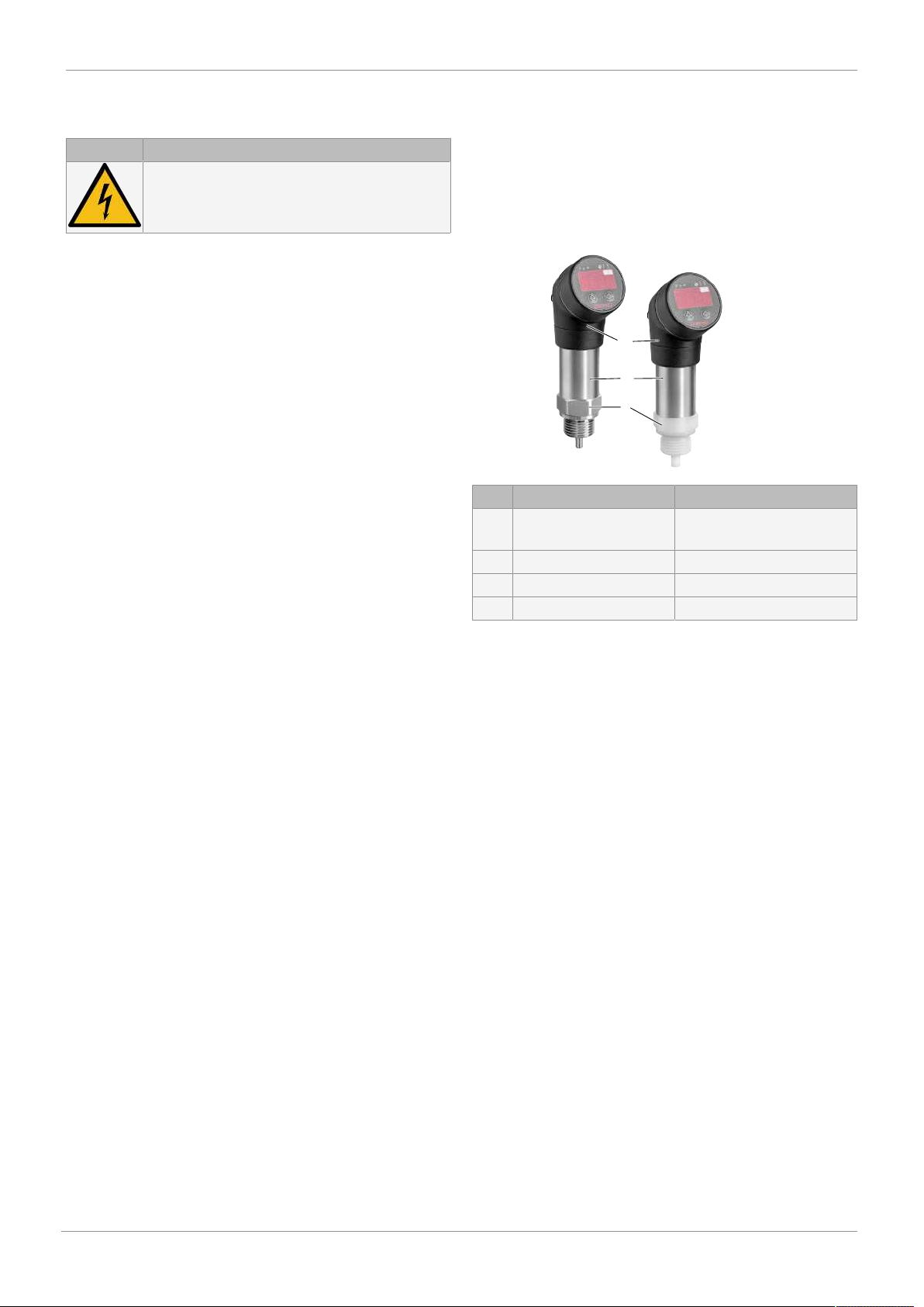
3.1 Construction
Temperature transducer/switch
2
1
3
Item Name Materials
1* Pressure connection 1.4404 stainless steel or
PVDF
2 Housing 1.4404 stainless steel
3 Display housing PA 6.6
Seals* FPM or EPDM
* Media wetted
3 Product description

www.gemu-group.com6 / 28GEMÜ 3240
4 Correct use
3.2 Description
The GEMÜ 3240 temperature transducer/switch is ideal for
precise measurements in a wide temperature range. The
sensor is suitable for both highly viscous, as well as contam-
inated media. It is also suitable for corrosive media thanks to
the high-quality material selection. Furthermore, it stands out
thanks to its extremely short installation length. The electrical
output signals can optionally be changed over between
power, current or switching outputs.
3.3 Function
The GEMÜ 3240 temperature transducer converts the phys-
ical variable of temperature into an electrical signal.
3.4 Product label
GEMÜ Gebr. Müller Apparatebau GmbH& Co. KG
Fritz-Müller-Straße 6-8
74653 Ingelfingen-Criesbach
SN: 23456789
3240G12T 714 MC1DPNAVGEMÜ 3240
PIN-Belegung:
Ub+: 1 Ausgang1: 4
Ub -: 3 Ausgang2: 2
Schirm: Stecker 2019
Eingang: -40 ... 150 °C
Ausgang1: IO-Link / PNP / NPN
Ausgang2: PNP / NPN / mA / V
Versorgung: 24 V DC
Order code
Serial
number
Product
type
Connection assignment
Signal
4 Correct use
DANGER
Danger of explosion!
▶GRisk of death or severe injury.
●Do not use the product in potentially
explosive zones.
WARNING
Improper use of the product!
▶Risk of severe injury or death.
▶Manufacturer liability and guarantee will be void.
●Only use the product in accordance with the operating
conditions specified in the contract documentation and in
this document.
The product is not intended for use in potentially explosive
areas.

5 Order data
The order data provide an overview of standard configurations.
Please check the availability before ordering. Other configurations available on request.
Order codes
1 Type Code
Temperature transducer, temperature switch 3240
2 Connection size Code
G 1/2 G12
3 Type of measurement Code
Temperature T
4 Material Code
1.4404 7
PVDF 20
5 Seal material Code
FPM 4
EPDM 14
6 Electrical connection Code
M12 x 1 plug, 4-pin M
7 Voltage/Frequency Code
24 V DC C1
8 Display Code
With display D
9 Output Code
PNP, NPN, 4-20mA, 0-10V, IO-Link switchable PNAV
Order example
Order option Code Description
1 Type 3240 Temperature transducer, temperature switch
2 Connection size G12 G 1/2
3 Type of measurement T Temperature
4 Material 7 1.4404
5 Seal material 4 FPM
6 Electrical connection M M12 x 1 plug, 4-pin
7 Voltage/Frequency C1 24 V DC
8 Display D With display
9 Output PNAV PNP, NPN, 4-20mA, 0-10V, IO-Link switchable
5 Order data
www.gemu-group.com 7 / 28 GEMÜ 3240

6 Technical data
6.1 Temperature
Media temperature: Stainless steel (code 7): -40 to 150 °C
PVDF (code 20): -30 to 125 °C
Ambient temperature: Stainless steel (code 7): -40 to 85 °C
PVDF (code 20): -30 to 85 °C
Storage temperature: Stainless steel (code 7): -40 to 85 °C
PVDF (code 20): -30 to 85 °C
6.2 Pressure
Operating pressure: Stainless steel (code 7): max. 160 bar
PVDF (code 20): max. 60 bar
6.3 Product compliance
EMC Directive: 2014/30/EU
6.4 Mechanical data
Installation position: Optional
Protection class: IP 67 acc. to EN 60529
Measuring range: Stainless steel (code 7): -40 to 150 °C
PVDF (code 20): -30 to 125 °C
Weight: 220 g
Switch-on time: 110 ms
Strength: 10 g / 25 Hz to 2 kHz to DIN EN 60068-2-6
500 g / 1 ms to DIN EN 60068-2-27
www.gemu-group.com8 / 28GEMÜ 3240
6 Technical data

6.5 Electrical data
6.5.1 Power supply standard
Supply voltage: 24 V DC (-5/+10%)
Current consumption: ≤ 40 mA
Reverse battery protec-
tion:
Yes
Short-circuit proof: Yes
Duty cycle: Continuous duty
Electrical connection
type:
M12 connector, 4-pin
Plug design A, DIN EN 175301-803
6.5.2 Electrical output
Supply voltage: 18 - 30 V DC
Output signal: Output 1: Switchable between NPN, PNP switching outputs, IO-Link
output 2: Switchable between NPN, PNP switching outputs, 4 to 20 mA, 0 to 10 V
Load resistor: Rmin = 10 kΩ
Rmax = 330 Ω
Max. switching current: 200 mA
Accuracy: ≤ ± 0.35% FSO
Switching output
Switch point: ≤ ± 0.5% FSO
Characteristic deviation in accordance with IEC 60770 – limiting value adjustment (non-linearity,
hysteresis, reproducibility)
Repetition: ≤ ± 0.2% FSO
Temperature drift: ≤ ± 0.3 °C + 0.005 + T
Switching frequency: Max. 170 Hz
Switching cycles: > 100 x 106
GEMÜ 3240www.gemu-group.com 9 / 28
6 Technical data

7 Specific data relating to IO-Link
Transmission rate: 38,400 baud, COM2
IO-Link specification: V1.1, slave
SIO operation: Yes
IEC Guideline: 61131-9
www.gemu-group.com10 / 28GEMÜ 3240
7 Specific data relating to IO-Link
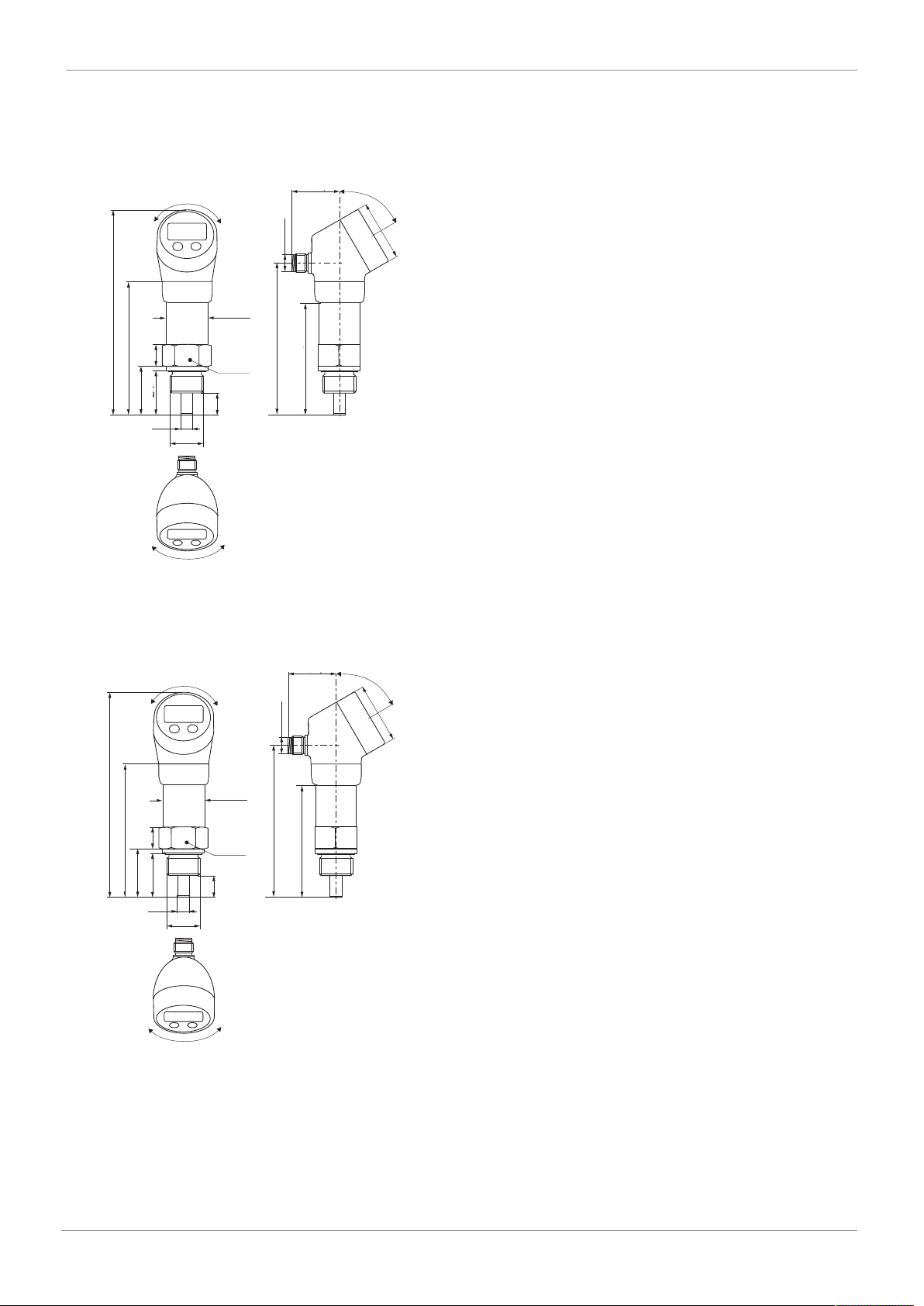
8 Dimensions
8.1 Device with pressure connection 1.4404 (code 7)
G 1/2
Ø26,5
SW27
85,5
27
24
133
-210° / +100°
11
32,5
60°
Ø40
97,5
71,5
M12x1
-110° / +220°
10
Ø5
3.37 / 85.5
5.24 /133
Ø 0.2 / 5
1.06 / 27
0.39 / 10
0.95 / 24
Ø 1.04 /
26.5
0.43 / 11
3.84 / 97.5
2.81 / 71.5
1.28 / 32.5
Ø 1.56 / 40
Dimensions in inch / mm
8.2 Device with pressure connection PVDF (code 20)
G 1/2
Ø26,5
SW27
84
27
24
132
-210° / +100°
10
32,5
60°
Ø40
96
70
M12x1
-110° / +220°
10
Ø6
3.31 / 84
5.18 /132
Ø 0.24 / 6
1.06 / 27
0.39 / 10
0.95 / 24
Ø 1.04 /
26.5
0.39 / 10
3.78 / 96
2.76 / 70
1.28 / 32.5
Ø 1.56 / 40
Dimensions in inch / mm
GEMÜ 3240www.gemu-group.com 11 / 28
8 Dimensions
www.gemu-group.com12 / 28GEMÜ 3240
9 Manufacturer's information
9 Manufacturer's information
9.1 Delivery
●Check that all parts are present and check for any damage
immediately upon receipt.
The product's performance is tested at the factory. The scope
of delivery is apparent from the dispatch documents and the
design from the order number.
9.2 Transport
1. Only transport the product by suitable means. Do not drop.
Handle carefully.
2. After the installation dispose of transport packaging ma-
terial according to relevant local or national disposal regu-
lations / environmental protection laws.
9.3 Storage
1. Store the product free from dust and moisture in its ori-
ginal packaging.
2. Avoid UV rays and direct sunlight.
3. Do not exceed the maximum storage temperature (see
chapter "Technical data").
4. Do not store solvents, chemicals, acids, fuels or similar
fluids in the same room as GEMÜ products and their spare
parts.
10 Installation in piping
10.1 Installation and safety information
DANGER
Risk of lightning strike!
▶If there is an elevated risk of the device
being damaged by lightning or over-
voltage, an effective lightning protec-
tion system must additionally be put in
place.
DANGER
Use of the product as a stepladder
▶The housings are not designed to be used as a stepladder
for climbing in the plant. They can be damaged if used in
this way and their function impaired. If the housing is
damaged, water, dirt and combustible material can accu-
mulate in the housing interior. This can cause a short-cir-
cuit. Furthermore, the deposits can cause the device to
overheat and may result in an explosion.
NOTICE
▶All interconnected components must be intrinsically safe.
The operator is responsible for ensuring that the entire
system (the entire circuit) is intrinsically safe.
NOTICE
▶Handle the unprotected diaphragm with extreme care, as
it is very easily damaged.
NOTICE
▶For use in steam pipes, provide a cooling zone.
NOTICE
▶During installation, avoid high mechanical stresses on the
pressure connection. This can result in the characteristic
shifting or in damage, particularly for very narrow pres-
sure ranges and for devices with a plastic pressure con-
nection.
NOTICE
▶With hydraulic systems, orientate the device such that the
pressure connection is facing upwards. (Vent hole)
NOTICE
▶If the device is to be installed with the pressure connec-
tion at the top, make sure that no liquid flows away along
the housing as this could result in moisture and dirt
blocking the gauge reference in the housing and, in turn,
to the equipment malfunctioning. Where necessary, re-
move dust and dirt from the edge of the electrical con-
nection's union.

www.gemu-group.com 13 / 28 GEMÜ 3240
NOTICE
▶Make sure that you do not remove the packaging and pro-
tection caps from the device until you are just about to in-
stall it, so that you do not damage the diaphragm or the
threads.
▶Keep the protection caps. Dispose of packaging properly.
10.2 Installing outdoors and in damp conditions
1. Electrically connect the device as soon as it is installed, or
take measures to prevent the ingress of moisture, e.g. us-
ing a suitable protection cap. (The stated protection class
applies to the device once it is connected.)
2. When installing the device, position it such that splashed
water and condensation can drain away. Liquid must not
be allowed to accumulate on sealing surfaces.
3. For devices with a cable outlet, the outgoing cable must
be routed downwards. If the cable has to be routed up-
wards, this must be implemented in an elbow that is direc-
ted downwards.
4. Install the device such that it is protected from direct sun-
light. In the worst case scenario, exposure to direct sun-
light can result in the permissible operating temperature
being exceeded. This must be completely avoided when
using the device in Ex areas.
5. Install devices with a gauge reference in the housing
(small hole next to the electrical connection) such that the
gauge reference needed for the measurement is protected
from dirt and moisture. If the measuring transducer is ex-
posed to liquid, the gauge reference will become blocked,
preventing the air pressure from equalizing. It is not pos-
sible to measure accurately in this situation, and the
measuring transducer may be damaged as a result.
10.3 Installation steps for connections in accordance
with DIN 3852
NOTICE
▶Do not use any additional sealing material such as
oakum, hemp or Teflon tape.
The O-ring must sit in the groove provided.
The O-ring is not damaged.
The sealing surface of the part that accommodates it must be
free of defects. (RZ 3.2)
1. Screw the device onto the mounting thread by hand.
2. Devices with a knurled collar must be screwed on tightly
by hand
3. Devices with a wrench surface must be tightened with a
suitable open-end wrench.
Steel wrench surface:
G1/4": Approx. 5 Nm
G1/2": Approx. 10 Nm
Plastic wrench surface:
Max. 3 Nm
10.4 Installation steps for connections in accordance
with EN 837
A suitable seal that is compatible with the measurement me-
dium and the temperature that is to be measured must be
provided (e.g. a copper gasket).
The sealing surface of the part that accommodates it must be
flawless (RZ 6.3).
1. Screw the device onto the mounting thread by hand.
2. Then tighten it with the open-end wrench:
G1/4": Approx. 20 Nm
G1/2": Approx. 50 Nm
NOTICE
▶Observe the permissible pressures in accordance with EN
837
G1/4" EN 837 PN ≤ 600 bar The counterpart
must be made from
steel in accordance
with DIN 17440
with a strength of
Rp0.2 ≥ 190 N/mm2.
G1/2" EN 837 PN ≤ 1000 bar
G1/4" EN 837 PN > 600 bar,
PN ≤ 1000 bar
The counterpart
must be made from
steel in accordance
with DIN 17440
with a strength of
Rp0.2 ≥ 260 N/mm2.
G1/2" EN 837 PN > 1000 bar,
PN ≤ 1600 bar
10 Installation in piping
www.gemu-group.com14 / 28GEMÜ 3240
11 Electrical connection
11 Electrical connection
Connect the product in accordance with the pin assignment.
11.1 Connection and safety information
Devices with cable glands and cable sockets
1. Ensure that the outside diameter of the cable used is
within the permissible clamping range (cable gland M12 x
1.5 cable dia. 3–6.5 mm, cable socket ISO 4400 cable dia.
4.5–10 mm). In addition, make sure that the cable is
seated securely in the cable gland, without any gaps.
2. Use a shielded, twisted multicore cable for the electrical
connection.
Devices with a cable outlet
Comply with the following minimum bend radii when laying
the cable:
- Cable without air hose:
Fixed in place: 5 x cable diameter
Flexible use: 10 x cable diameter
- Cable with air hose:
Fixed in place: 10 x cable diameter
Flexible use: 20 x cable diameter
On devices with a cable outlet and integrated vent tube, the
PTFE filter on the cable end on the gauge tube must not be
damaged or removed.
NOTICE
▶Cables used for gauge devices have a vent tube for equal-
izing the pressure. Route the cable end into an area or
suitable terminal box that is as free from moisture and
corrosive gases as possible in order to prevent damage.
11.2 3-wire system (output code PNAV)
1
4
3
2
Pin Description
1 Supply +
2 Switching output / Signal
3 Supply -
4 Switching output / Communication
P
I/U
UB
R
L
A/V
R
L
Switching output/
communication
Supply +
Supply -
IO-Link master
Switching output/signal
12 Commissioning
1. The device must be properly installed
2. The device must not exhibit any visible defects
3. The device must be operated within the specifications
(see datasheet and EC type examination certificate).
13 Operation
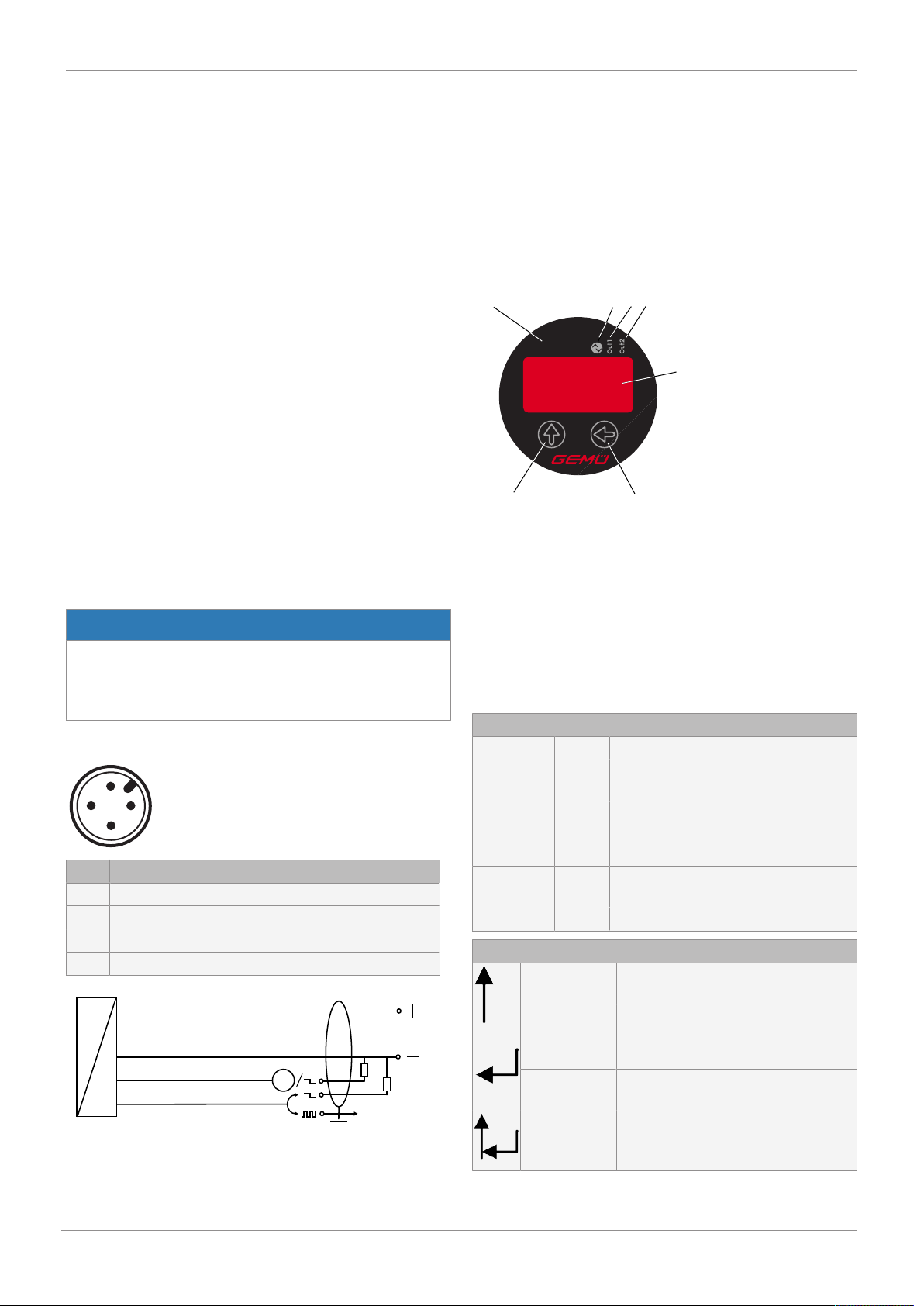
13.1 Operating and display elements
°C
°F
K
134
5
6
7
2
Fig.1: Operating screen for device with two switching outputs
1 = Three LEDs for displaying units
2 = LED IO-Link red: Status indication IO-Link
3 = LED Out 1 yellow: Switching output 1 status indication
4 = LED Out 2 green: Switching output 2 status indication
5 = Seven-segment display for measured value and paramet-
ers
6 = Key for moving within a menu
7 = Key for moving from menu to menu
LED status in normal mode
Red LED On IO-Link active (master slave operation)
Off IO-Link inactive (no master slave oper-
ation)
Yellow LED On Switch point 1 reached, switching out-
put active
Off Switch point not reached
Green LED On Switch point 2 reached, switching out-
put active
Off Switch point not reached
Tastenfunktion
Press briefly Scroll from menu 1 to menu 5, then
return to the display
Press and
hold
Increase parameter values quickly
Press briefly Select a menu item in a menu
Press and
hold
Apply the set parameter and return to
the current menu item
Press both
keys at the
same time
Return to the display
The device is configured in accordance with VDMA 24574-1.
www.gemu-group.com 15 / 28 GEMÜ 3240
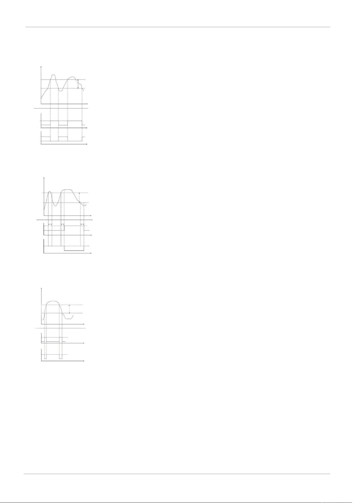
13.2 Switching and switch-back characteristics
Temperature T
Time t
SP Hyste-
resis
(SP-rP)
rP
Time t
Time t
Ou make contact
Hno
1
1
0
0
Ou make contact
Hnc
Fig.2: Switching and switch-back characteristics for the hyster-
esis function in the temperature-time diagram
Temperature T
SP
rP
Hysteresis
(SP-rP)
Time t
Time t
Time t
Ou make contact
Hno 1
0
1
0
Ou break contact
Hnc
dS dS dR
Fig.3: Switching and switch-back delay for the hysteresis func-
tion in the temperature-time diagram
Temperature T
Temperature
window
Time t
Time t
FH
FL
1
0
1
0
Ou make contact
Fno
Ou break contact
Fnc
Fig.4: Switching and switch-back characteristics for the win-
dow function in the temperature-time diagram
13 Operation
www.gemu-group.com16 / 28GEMÜ 3240
13 Operation
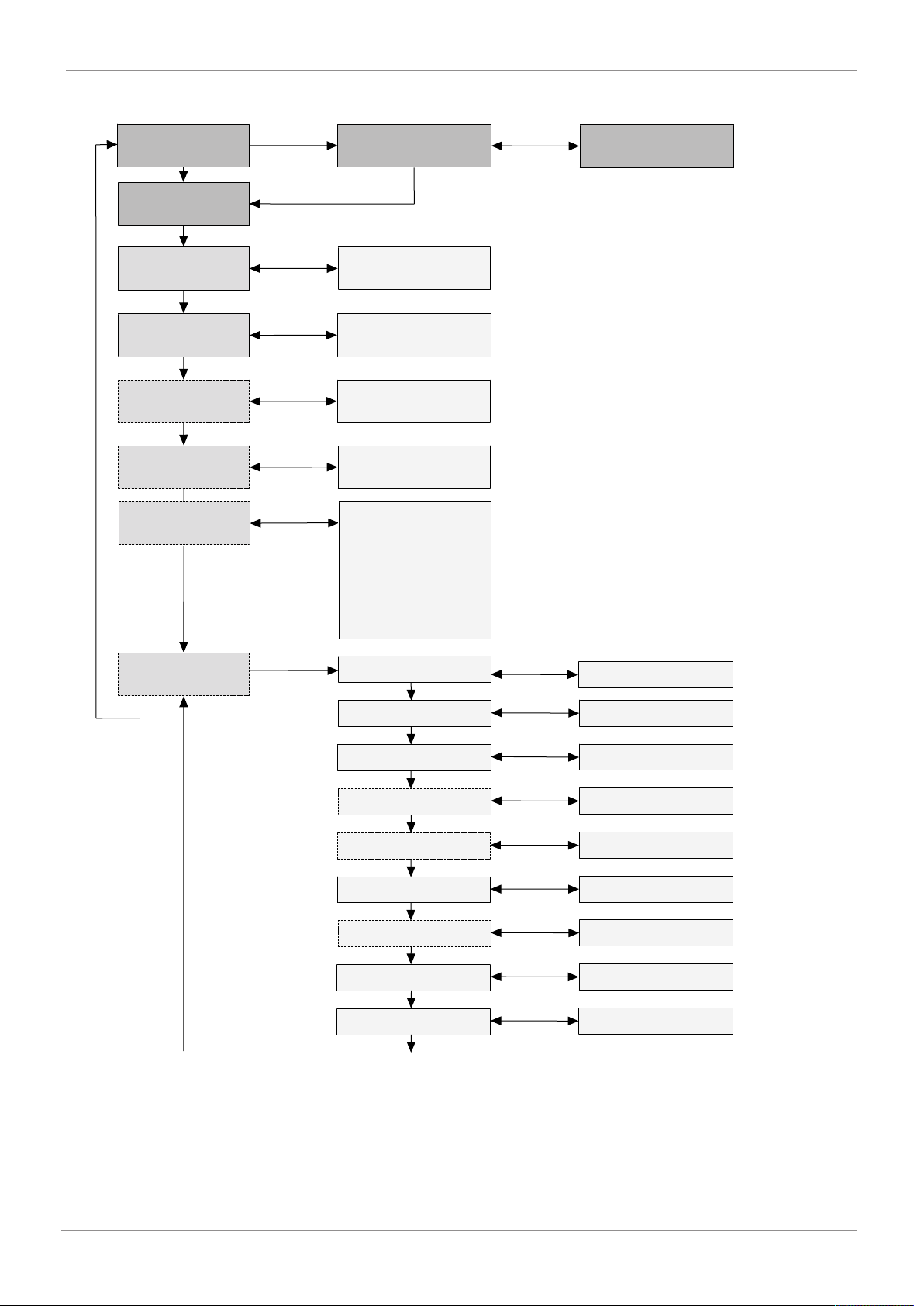
13.3 Structure of the menu system
Display mode
PW = 0000
Password prompt
¹
PW 0000 XXXX
Programming
mode
Menu 1
SP1/FH1
Switch point 1
Value
e.g. 80 °C
Menu 2
RP1/FL1
Switch-back point 1
Value
e.g. 70 °C
Menu 3
SP2/FH2
Switch point 2
Value
e.g. 55 °C
Menu 4
RP2/FL2
Switch-back point 2
Value
e.g. 50 °C
Menu 5
EF
Extended functions
Reset
Menu 5.1 YES/NO
Switch-on delay 1
Menu 5.2 Value
e.g. 0 to 50 s
Switch-back delay 1
Menu 5.3 Value
e.g. 0 to 50 s
Switch-on delay 2
Menu 5.4 Value
e.g. 0 to 50 s
Switch-back delay 2
Menu 5.5 Value
e.g. 0 to 50 s
Menu 5.6
Output 2
Menu 5.7 Parameter
Hno, Hnc, Fno, Fnc
Output 1
Parameter
Hno, Hnc, Fno, Fnc
Switching units
Menu 5.8 Parameter
°C, °F, K
Additional menu
ASt2/AEn2
If output signal 2
is active (5/17)
analogue output 2
(change option
± 5 % for initial value and
90–100% for end value of
the measuring range),
see 14.8 Setting the
offset and end value.
FLIP
Menu 5.9 Rotate display
indication by 180°
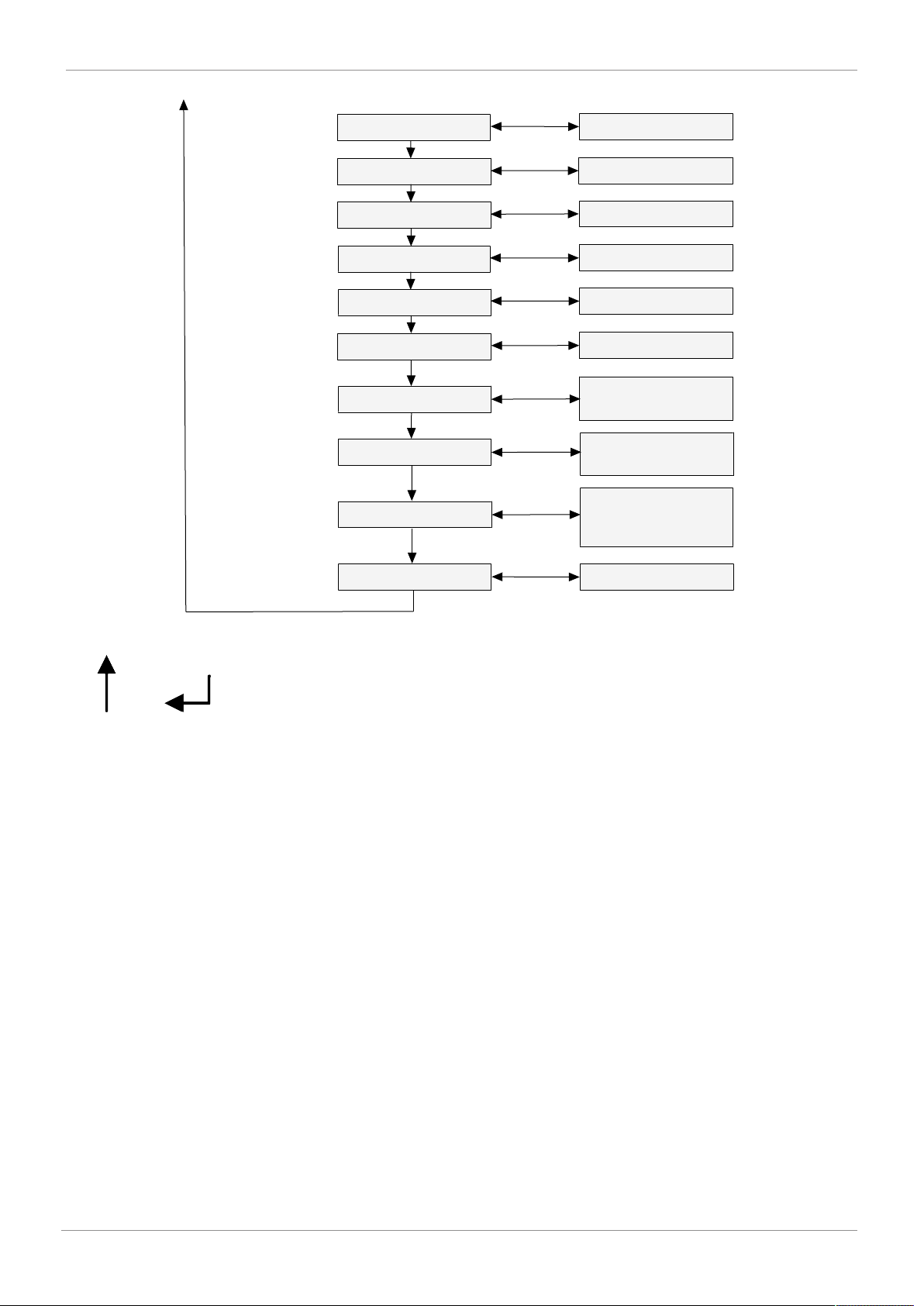
www.gemu-group.com 17 / 28 GEMÜ 3240
Min. value
Menu 5.10 Display
Max. value
Menu 5.11 Display
Delete min./max. value
Menu 5.12 Display
Delete min./max. value Perform
Zero point adjustment
Menu 5.13
YES/NO
Measured value damping
Menu 5.14
Value
10–1000 ms
Access protection
Menu 5.15
Value
e.g. 0000–9999
(0000 = no password)
Output signal 1
Menu 5.16 Switchover option
between
PNP and NPN function
Output signal 2
Menu 5.17
Switchover option
between
PNP, NPN function,
4–20 mA and 0–10 V
Menu 5.18 Display
Operating time
Using the menu
Left key Right key
1. Call up menu 1 with the left key.
2. Display the values for switch point 1 using the right key. The selected value flashes.
3. Select a value with the left key. Confirm the selected value with the right key and return to menu 1.
4. Call up the next menu with the left key and set the value as described in points 2 and 3.
5. Call up menu 5 with the left key.
6. Call up the first submenu 5.1 with the right key and set the value as described in points 2 and 3.
Note:
If no key is pressed for 60 seconds, the program returns to the display without saving the changed value.
The menus with dotted edges are not included on sensors with analogue output.
13 Operation

www.gemu-group.com18 / 28GEMÜ 3240
13 Operation
13.4 Menu list
First menu level
SP 1 / SP2
FH 1 / FH2
Menu: 1 and 3
Setting the switch on points
Setting the respective value from which the switch point 1 or 2 should be activated. If the window func-
tion in the menu 5/6 or 5/7 is activated, the value of the switch point is the upper temperature limit of
the window (WindowHigh).
rP 1* / rP 2*
FL 1 / FL2
Menu: 2 and 4
Setting the switch-back points
Setting the respective value from which the switch-back point 1 and 2 should be activated. If the window
function in the menu 5/6 or 5/7 is activated, the value of the switch-back point is the lower temperature
limit of the window (WindowLow).
ASt2 / AEn2
* Additional menu
If output signal 2 is active (5/17)
Analogue output 2 (change option ± 5% for initial value and 90–100% for end value of the measuring
range), see 14.8 Setting the offset and end value.
EF
Menu: 5
Extended functions
(Transition to menu level two)
Second menu level
rES
Menu: 5/1
Reset
Restore all adjustable parameters to the as-delivered state and delete the min. and max. values
dS 1 / ds 2
Menu: 5/2 and 5/4
Setting the switch-on delay
Setting the value for the switch-on delay after reaching switch-on point 1 or 2 (adjustable 0.0 to 50.0 s)
dr 1 / dr 2
Menu: 5/3 and 5/5
Setting the switch-off delay
Setting the value for the switch-off delay after reaching switch-off point 1 or 2 (adjustable 0.0 to 50.0 s)
ou1 / ou2
Menu: 5/6 and 5/7
Setting the switching outputs 1 and 2
Switching function of the switching outputs:
Hno = Hysteresis function, make contact
Hnc = Hysteresis function, break contact
Fno = Window function, make contact
Fnc = Window function, break contact
Uni
Menu: 5/8
Switching units
Select the physical unit of measure
for the displayed and set pressure values:
C = °C F = °F
K = K
FLIP
Menu: 5/9 Rotate display indication by 180°
Lo
Menu: 5/10
Min. value (display only)
Display of the minimum temperature that was present during measurement (the value is lost if the
power supply is interrupted)
Hi
Menu: 5/11
Max. value (display only)
Display of the maximum temperature that was present during measurement (the value is lost if the
power supply is interrupted)
----
Menu: 5/12
Delete the min. and max. values
The display confirms that the values have been deleted
Set0
Menu: 5/13
Zero point adjustment
Setting/correction of the zero point of the display indication and the analogue output signal by up to ±
3% of the measuring range
dAP
Menu: 5/14
Measured value damping
Setting the value for damping (0 to 1000 ms in 10 ms steps)

www.gemu-group.com 19 / 28 GEMÜ 3240
Second menu level
codE
Menu: 5/15
Access protection
Setting the password for access protection of the menu
0000 = no password (deactivated);
1000–9999 adjustable (activated)
To reset the password, please contact GEMÜ.
o1
Menu: 5/16
Output signal 1
Switchover option between PNP and NPN function
o2
Menu: 5/17
Output signal 2
Switchover option between PNP, NPN function, 4 to 20 mA and 0 to 10 V
Hcnt
Menu: 5/18
Display of the operating time in [h]
Display
Menu item Designation Default setting Own setting
Menu 1 SP1/FH1 Switch point 1 / WindowHigh 1 75% of the nominal
temperature
Menu 2 rP1/FL1 Switch-back point 1 / WindowLow 1 74% of the nominal
temperature
Menu 3 SP2/FH2 Switch point 2 / WindowHigh 2 85% of the nominal
temperature
Menu 4 rP2/FL2 Switch-back point 2 / WindowLow 2 84% of the nominal
temperature
Menu 5:2 dS1 Delay switching time 1 0 sec
Menu 5:3 dr1 Delay back switching time 1 0 sec
Menu 5:4 dS2 Delay switching time 2 0 sec
Menu 5:5 dr2 Delay back switching time 2 0 sec
Menu 5:6 ou1 Switching function of output 1 Hno
Menu 5:7 ou2 Switching function of output 2 Hno
Menu 5:8 uni Units °C
Menu 5:14 dAP Measured value damping 0 ms
Menu 5:15 code Password 0000
Menu 5:16 01 Output signal 1 PNP
Menu 5:17 02 Output signal 2 PNP
13 Operation

www.gemu-group.com20 / 28GEMÜ 3240
14 IO-Link Interface
14 IO-Link Interface
14.1 General device information
Baud rate COM 2 (38.4 kBaud)
Process data length input 2 bytes
Minimum cycle time 5 ms
IO-Link version V1.1
SIO mode Yes
14.2 SIO mode (standard IO mode)
In this mode, the sensor operates in the same way as a nor-
mal temperature sensor with standard output signals. The di-
gital output is always at pin 4 (output 1) of the M12 plug. Pin 2
(output 2) can be an analogue or additional digital output, de-
pending on the version.
14.3 IO-Link mode (communication mode)
The temperature sensor switches to the IO-Link communica-
tion mode when it is operating under an IO-Link master. IO-
Link communication is only possible via pin 4 of the M12
plug.
14.4 Process data
The process data length of the sensor is 16 bits. Both the
switching states (BCD1 and BCD2) and the current measured
values are transferred. The 14 bits of the measured value are
scaled according to the sensor's measuring range.
15 bits 14–2 1 0
Signed
Bit
Measured
value
BDC2 / output 2 BDC1 / output 1
14.5 Error Codes
Error Code Description
0x8011 Index not available
0x8012 Subindex not available
0x8023 Access Denied
0x8030 Parameter value out of range
0x8033 Parameter length overrun
0x8034 Parameter length underrun
14.6 Event Codes
IO-Link
1.1 Event
Codes
IO-Link 1.0
Event
Codes
Device
status
Type
No malfunc-
tion
0x0000 0x0000 0 Notification
General
malfunc-
tion. Un-
known error
0x1000 0x1000 4 Error
Process
variable
range over-
run. Pro-
cess Data
uncertain
0x8C10 0x8C10 2 Warning
Process
variable
range un-
der-run.
Process
Data uncer-
tain
0x8C30 0x8C10 2 Warning
Other manuals for 3240
1
Table of contents
Other GEM Transducer manuals


Popular Transducer manuals by other brands

Raymarine
Raymarine Wind Vane Service manual

GHM-Martens
GHM-Martens MU125 operating manual

HBM
HBM T5 Mounting instructions

S+S Regeltechnik
S+S Regeltechnik PREMASGARD 1110 Operating Instructions, Mounting & Installation

Clark Synthesis
Clark Synthesis TST429 installation guide

Mercoid
Mercoid PBLTX Series Installation and operating instructions


M-system
M-system M5XWTU instruction manual

SIAP+MICROS
SIAP+MICROS t001 TTEP User manual and maintenance

Desoutter
Desoutter DLT Series Product instructions

novotechnik
novotechnik TEX Series user manual

MAMAC SYSTEMS
MAMAC SYSTEMS PR-264 technical information

Fairchild
Fairchild T7800 Series Installation, operation and maintanance manual