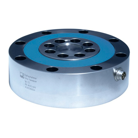
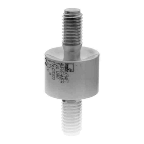
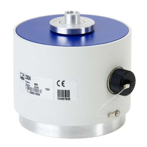
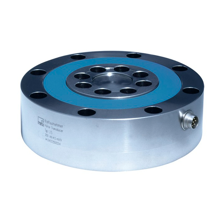
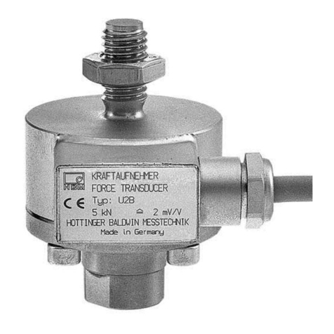
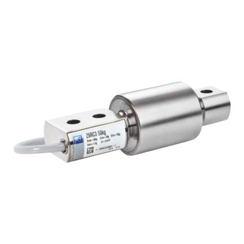
HBM Z30 User manual

Force Transducer with
S.G. Measurement System
Z30, Z30–G
Mounting Instructions
B 20.Z30.10 en
SUNSTAR传感与控制 http://www.sensor-ic.com/ TEL:0755-83376549 FAX:0755-83376182 E-MAIL:[email protected]
SUNSTAR自动化 http://www.sensor-ic.com/ TEL: 0755-83376489 FAX:0755-83376182 E-MAIL:[email protected]

SUNSTAR传感与控制 http://www.sensor-ic.com/ TEL:0755-83376549 FAX:0755-83376182 E-MAIL:[email protected]
SUNSTAR自动化 http://www.sensor-ic.com/ TEL: 0755-83376489 FAX:0755-83376182 E-MAIL:[email protected]
3
Z30
HBM 23.8.00
Contents Page
Safety instructions 4. . . . . . . . . . . . . . . . . . . . . . . . . . . . . . . . . . . . . . . . . . . . . .
1 Scope of supply 7. . . . . . . . . . . . . . . . . . . . . . . . . . . . . . . . . . . . . . . . . . . . .
2 Applicationnotes 8. . . . . . . . . . . . . . . . . . . . . . . . . . . . . . . . . . . . . . . . . . . .
3 Structure and mode of operation 8. . . . . . . . . . . . . . . . . . . . . . . . . . . . . .
3.1 Measuring body 8. . . . . . . . . . . . . . . . . . . . . . . . . . . . . . . . . . . . . . . . . . .
3.2 Housing 9. . . . . . . . . . . . . . . . . . . . . . . . . . . . . . . . . . . . . . . . . . . . . . . . . .
3.3 Disturbance variables 9. . . . . . . . . . . . . . . . . . . . . . . . . . . . . . . . . . . . . .
4 Conditionson site 10. . . . . . . . . . . . . . . . . . . . . . . . . . . . . . . . . . . . . . . . . . .
4.1 Ambient temperature 10. . . . . . . . . . . . . . . . . . . . . . . . . . . . . . . . . . . . . . .
4.2 Moisture 10. . . . . . . . . . . . . . . . . . . . . . . . . . . . . . . . . . . . . . . . . . . . . . . . .
4.3 Air pressure 10. . . . . . . . . . . . . . . . . . . . . . . . . . . . . . . . . . . . . . . . . . . . . .
4.4 Chemical effects 10. . . . . . . . . . . . . . . . . . . . . . . . . . . . . . . . . . . . . . . . . .
5 Mechanicalinstallation 11. . . . . . . . . . . . . . . . . . . . . . . . . . . . . . . . . . . . . . .
5.1 Important precautions during installation 11. . . . . . . . . . . . . . . . . . . . . .
5.2 General installation guidelines 11. . . . . . . . . . . . . . . . . . . . . . . . . . . . . . .
5.3 Mounting accessories for tensile loading/compressive loading 12. . .
5.3.1 Installation drawing for compressive loading 12. . . . . . . . . . . .
6 Electrical connection 13. . . . . . . . . . . . . . . . . . . . . . . . . . . . . . . . . . . . . . . . .
6.1 Instructions for cabling 13. . . . . . . . . . . . . . . . . . . . . . . . . . . . . . . . . . . . .
6.2 Pin assignment 13. . . . . . . . . . . . . . . . . . . . . . . . . . . . . . . . . . . . . . . . . . .
7 Specifications 15. . . . . . . . . . . . . . . . . . . . . . . . . . . . . . . . . . . . . . . . . . . . . . .
8 Dimensions Z30, Z30–G 17. . . . . . . . . . . . . . . . . . . . . . . . . . . . . . . . . . . . . .
9 Declaration of conformity 22. . . . . . . . . . . . . . . . . . . . . . . . . . . . . . . . . . . . .
SUNSTAR传感与控制 http://www.sensor-ic.com/ TEL:0755-83376549 FAX:0755-83376182 E-MAIL:[email protected]
SUNSTAR自动化 http://www.sensor-ic.com/ TEL: 0755-83376489 FAX:0755-83376182 E-MAIL:[email protected]
4Z30
HBM 23.8.00
Safety instructions
Use in accordance with the regulations
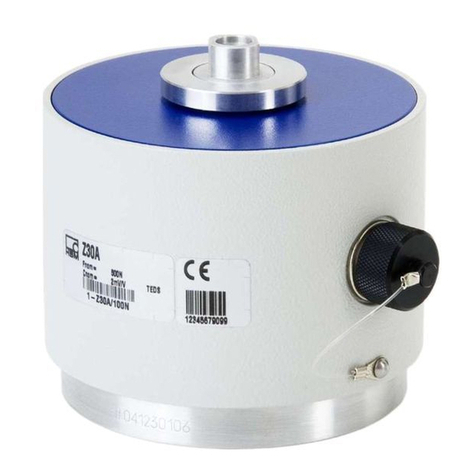
Z30, Z30–G type force transducers are used for high-precision force
measurements and for force reference measurements (transfer standard).
Use for any additional purpose shall be deemed to be not in accordance with
the regulations.
In the interests of safety, the transducer should only be operated as described
in the Mounting Instructions. It is also essential to observe the appropriate
legal and safety regulations for the application concerned during use. The
same applies to the use of accessories.
The transducer is not a safety element within the meaning of its use as inten-
ded. Proper and safe operation of this transducer requires proper transporta-
tion, correct storage, assembly and mounting and careful operation and main-
tenance.
General dangers of failing to follow the safety instructions
The Z30, Z30–G force transducer corresponds to the state of the art and is
fail-safe. The transducers can give rise to remaining dangers if they are
inappropriately installed and operated by untrained personnel.
Everyone involved with the installation, commissioning, maintenance or repair
of a force transducer must have read and understood the Mounting Instruc-
tions and in particular the technical safety instructions.
Remaining dangers
The scope of supply and performance of the transducer covers only a small
area of force measurement technique. In addition, equipment planners,
installers and operators should plan, implement and respond to the safety
engineering considerations of force measurement technique in such a way as
to minimise remaining dangers. Prevailing regulations must be complied with
at all times. There must be reference to the remaining dangers connected with
force measurement technique.
SUNSTAR传感与控制 http://www.sensor-ic.com/ TEL:0755-83376549 FAX:0755-83376182 E-MAIL:[email protected]
SUNSTAR自动化 http://www.sensor-ic.com/ TEL: 0755-83376489 FAX:0755-83376182 E-MAIL:[email protected]
5
Z30
HBM 23.8.00
In these mounting instructions remaining dangers are pointed out using the
following symbols:
Symbol: DANGER
Meaning:
Maximum danger level
Warns of an imminently dangerous situation in which failure to comply with
safety requirements will result in death or serious physical injury.
Symbol: WARNING
Meaning:
Dangerous situation
Warns of a potentially dangerous situation in which failure to comply with
safety requirements can result in death or serious physical injury.
Symbol: ATTENTION
Meaning:
Potentially dangerous situation
Warns of a potentially dangerous situation in which failure to comply with
safety requirements could result in damage to property or some form of
physical injury.
Symbol: NOTE
Means that important information about the product or its handling is being
given.
Symbol:
Meaning:
CE mark
The CE mark signals a guarantee by the manufacturer that his product meets
the requirements of the relevant EC directives (see Declaration of conformity
at the end of this document).
SUNSTAR传感与控制 http://www.sensor-ic.com/ TEL:0755-83376549 FAX:0755-83376182 E-MAIL:[email protected]

SUNSTAR自动化 http://www.sensor-ic.com/ TEL: 0755-83376489 FAX:0755-83376182 E-MAIL:[email protected]
6Z30
HBM 23.8.00
Prohibition of own conversions and modifications
The transducer must not be modified from the design or safety engineering
point of view except with our express agreement. Any modification shall
exclude all liability on our part for any damage resulting therefrom.
Qualified personnel
These transducers are only to be installed by qualified personnel strictly in
accordance with the technical data and with the safety rules and regulations
which follow. It is also essential to observe the appropriate legal and safety
regulations for the application concerned. The same applies to the use of
accessories.
Qualified personnel means persons entrusted with the installation, fitting,
commissioning and operation of the product who possess the appropriate
qualifications for their function.
Conditions on site
Protect the transducer from damp and weather influences such as rain, snow,
etc.
Maintenance
The Z30, Z30–G force transducer is maintenance free.
Accident prevention
Although the specified nominal force in the destructive range is several times
the full scale value, the relevant accident prevention regulations from the
trade associations must be taken into consideration.
SUNSTAR传感与控制 http://www.sensor-ic.com/ TEL:0755-83376549 FAX:0755-83376182 E-MAIL:[email protected]
SUNSTAR自动化 http://www.sensor-ic.com/ TEL: 0755-83376489 FAX:0755-83376182 E-MAIL:[email protected]
7
Z30
HBM 23.8.00
1 Scope of supply
•Force transducer Z30/Z30-G1)2)
•Operating Manual Z30, Z30–G
Accessories (not included in the scope of supply)
•DKD calibration certificate according to EN10002–3
Order no. K–CAL–FD
(Class 00 according to DIN EN10002–3 resp. ISO376 guaranteed;
Specifications see Z30-G)
•Knuckle eyes ZGW/ZGOW
for 50 N to 1000 N: Order no. 1–U1R/200kg/ZGW
for 2 kN to 10 kN: Order no. 1–U2A/1t/ZGUW
•Thrust piece
(recommended for precision measurements, for example
EN10002–3–Calibrations)
for 50 N to 1000 N: EDO3/1kN Order no. 3–9219.0741
for 2 kN to 10 kN: EDO4/50kN Order no. 3–9219.0719
•Load button
for 50 N to 1000 N: Order no. 1–U1R/200kg/ZL
for 2 kN to 10 kN: Order no. 3–9202.0140
•Cable/male connector
Connection cable Kab 139A–6, 6m, with cable socket 723 and
unterminated;
Order number: 1–KAB139A–6
Connector MS3106PEMV fitted to Kab139A;
Order number: D–MS/MONT
15–pin D–Sub connector (male) fitted to Kab139A;
Order no.: D–15D/MONT
1) Z30–G is only available in conjunction with DKD calibration carried out by HBM according to EN10002–3.
2) The calibration certificate must be ordered separately (see accessories).
SUNSTAR传感与控制 http://www.sensor-ic.com/ TEL:0755-83376549 FAX:0755-83376182 E-MAIL:[email protected]
SUNSTAR自动化 http://www.sensor-ic.com/ TEL: 0755-83376489 FAX:0755-83376182 E-MAIL:[email protected]

8Z30
HBM 23.8.00
2 Application notes
Force transducer Z30:
Series Z30 precision force transducers measure tensile and compressive
forces.
They measure static and quasi-static forces with great accuracy and
reproducibility and therefore require judicious handling. You must be
particularly vigilant when transporting and installing the devices. If the
transducers are dropped or jolted, permanent damage could be caused.
Z30–G force transducers complete with DKD certificate from HBM:
Force transducer calibrated to guaranteed class 00 according to DIN
EN10002–3 or ISO / FDIS 376.
As standard these transducers are calibrated in the tensile direction. On
request they can also be calibrated in the compressive direction to DKD
standards.
The limits for permissible mechanical, thermal and electrical stresses are
stated in the specifications. Be sure to allow for them when planning, installing
and operating the measurement configuration .
SUNSTAR传感与控制 http://www.sensor-ic.com/ TEL:0755-83376549 FAX:0755-83376182 E-MAIL:[email protected]
SUNSTAR自动化 http://www.sensor-ic.com/ TEL: 0755-83376489 FAX:0755-83376182 E-MAIL:[email protected]

9
Z30
HBM 23.8.00
3 Structure and mode of operation
3.1 Measuring body
The measuring body comprises a system of measuring springs with strain
gauges (dual-beam spring element principle).
3.2 Housing
The enclosure provides protection against splashes and minor impacts.
3.3 Disturbance variables
Torsion, bending and transverse load are disturbance variables and are
therefore to be avoided. If necessary they can be remedied with HBM
mounting accessories (chapter 5.3 ).
The effects of temperature on the zero signal (S.G. bridge and housing) and
on the sensitivity are compensated.
Changes in the ambient pressure act as additive (subtractive) forces. These
are scarcely of importance when compared with large nominal loads.
SUNSTAR传感与控制 http://www.sensor-ic.com/ TEL:0755-83376549 FAX:0755-83376182 E-MAIL:[email protected]
SUNSTAR自动化 http://www.sensor-ic.com/ TEL: 0755-83376489 FAX:0755-83376182 E-MAIL:[email protected]

10 Z30
HBM 23.8.00
4 Conditions on site
4.1 Ambient temperature
The effects of temperature on the zero signal and on the sensitivity are
compensated. To achieve optimal measurement results the nominal
temperature range must be maintained. Temperature-induced measurement
errors can be caused by uneven cooling or heating (for example by radiant
heat). A radiation shield and all-round heat insulation bring about marked
improvements. They must not form a force shunt.
4.2 Moisture
Extreme humidity or a tropical climate should be avoided if this means that the
classified limit values are exceeded (degree of protection IP50 under DIN EN
60529).
4.3 Air pressure
Changes in air pressure have no effect on the force transducer since it is not
hermetically sealed.
4.4 Chemical effects
The aluminium enclosures of the transducers is protected by a powder
coating. If used in difficult environmental conditions (direct weather effects,
contact with media which encourage corrosion) additional protective
measures should be employed by the user.
SUNSTAR传感与控制 http://www.sensor-ic.com/ TEL:0755-83376549 FAX:0755-83376182 E-MAIL:[email protected]
SUNSTAR自动化 http://www.sensor-ic.com/ TEL: 0755-83376489 FAX:0755-83376182 E-MAIL:[email protected]

11
Z30
HBM 23.8.00
5 Mechanical installation
5.1 Important precautions during installation
– treat the transducer gently
– if measuring compressive forces, make sure there is a solid support
structure
– the force-introduction surfaces must be scrupulously clean and fully
load-bearing
– keep to the depths of engagement for threaded rods or knuckle eyes
– do not overload the transducer.
WARNING
If there is a risk of breakage through overload on the
transducer and thus a risk to persons, additional safety
measures are to be taken.
5.2 General installation guidelines
The measurement direction in which forces act on the transducer must be as
precise as possible.
WARNING
Torsion and bending moments, eccentric loading and
transverse forces result in measurement errors and if limit
values are exceeded, could destroy the transducer.
SUNSTAR传感与控制 http://www.sensor-ic.com/ TEL:0755-83376549 FAX:0755-83376182 E-MAIL:[email protected]
SUNSTAR自动化 http://www.sensor-ic.com/ TEL: 0755-83376489 FAX:0755-83376182 E-MAIL:[email protected]

12 Z30
HBM 23.8.00
5.3 Mounting accessories for tensile loading/compressive
loading
Knuckle eyes are available for installing with the Z30. These mounting
accessories prevent the introduction of torsional moments into the transducer.
Using two knuckle eyes will also exclude bending moments, shear loading
and eccentric loading. Knuckle eyes are mainly provided to deal with static
tensile loading on the transducer.
For dynamic loading, Z30 transducers must be installed free from play.
Knuckle eyes have only limited application in the case of dynamic loading,
since alternating dynamic stress increases the play in the universal joints and
falsifies the measured value. It also produces a self-amplifying load cycle
which can destroy the knuckle eyes. The breaking force is only 150% Fnom.
Thrust pieces EDO3/1kN or EDO4/50kN (see page 21) and two load buttons
(see page 20) are available for introducing compressive forces.
5.3.1 Installation drawing for compressive loading
F
Thrust piece
Load button
Transducer
Transducer Load button Thrust piece
Z30 / 50 N – 1000 N 1–U1R/200kg/ZL EDO3/1kN
Z30 / 2 kN – 10 kN 3–9202.0140 EDO4/50kN
SUNSTAR传感与控制 http://www.sensor-ic.com/ TEL:0755-83376549 FAX:0755-83376182 E-MAIL:[email protected]
SUNSTAR自动化 http://www.sensor-ic.com/ TEL: 0755-83376489 FAX:0755-83376182 E-MAIL:[email protected]

13
Z30
HBM 23.8.00
6 Electrical connection
6.1 Instructions for cabling
•Always use shielded, low-capacity measurement cable (HBM cables meet
these requirements).
•Do not lay measurement cable parallel to high-voltage power lines or
control circuits. If this is not possible (e.g. in cable ducts) protect the
measurement cable, e.g. with armoured steel tube and maintain a minimum
distance of 50 cm from the other cables. High-voltage power lines and
control lines should be twisted (15 turns per metre).
•Avoid stray fields of transformers, motors and contactors.
•Do not earth transducer, amplifier and display device more than once. All
the devices in the measurement chain are to be connected to the same
earthed conductor.
•The screen of the connection cable is connected to the transducer housing.
6.2 Pin assignment
Two 7-pin male device connectors are located on the enclosure (male
connectors, Series 723, see pages 17 and 18). To avoid creating force
bypasses through the cable, you can use either the lower or the lateral
connector, depending on the configuration.
If the transducer is connected according to the following connection diagram
then when the transducer has compressive loading the output voltage at the
measuring amplifier is positive.
Pin on
male connector Assignment Wire
colour
1Measurement signal (+) WH
2Excitation voltage (–) BK
3Excitation voltage (+) BU
4Measurement signal (–) RD
5No function –
6 Sensor circuit (+) GN
7Sensor circuit (–) GY
Fig. 6.1: Male connector, series 723 (screwed)
61
5
72
43
Male connector,
series 723
Top view
SUNSTAR传感与控制 http://www.sensor-ic.com/ TEL:0755-83376549 FAX:0755-83376182 E-MAIL:[email protected]
SUNSTAR自动化 http://www.sensor-ic.com/ TEL: 0755-83376489 FAX:0755-83376182 E-MAIL:[email protected]

14 Z30
HBM 23.8.00
WH (white)
BK (black)
RD (red)
BU (blue)
GN (green)
GY (grey)
shielding
Measurement signal (+) UA
Excitation voltage (+) UB
Sensor circuit (–)
Sensor circuit (+)
Excitation voltage (–) UB
Measurement signal (–) UA
Cable shielding, connected to housing
Fig. 6.2: Pin assignment on the unterminated Z30/Z30-G (for KAB139A–6
connection cable)
SUNSTAR传感与控制 http://www.sensor-ic.com/ TEL:0755-83376549 FAX:0755-83376182 E-MAIL:[email protected]
SUNSTAR自动化 http://www.sensor-ic.com/ TEL: 0755-83376489 FAX:0755-83376182 E-MAIL:[email protected]

15
Z30
HBM 23.8.00
7 Specifications
Type Z30 / Z30–G
Data according to VDI standards
2638
Nominal force Fnom N50 100 200 500 1000 2k 5k 10k
Accuracy class 0.03
Nominal sensitivity Cnom mV/V 2
rel. sensitivity deviation
(pressure) dc% 0.1
rel. tensile/compressive force
sensitivity difference dzd %0.1
rel. zero signal deviation ds,o %0.2 0.1 0.1
rel. zero point compensation1) fo%0.012
Rel. range (0.2Fnom to Fnom) at:1)
unchanged mounting position bi% 0.03 (typically 0.02)
different mounting positions b % 0.05 (typically 0.03)
Hysteresis (0.2Fnom to Fnom)1) u % 0.1
Linearity deviation dlin % 0.03
Effect of temperature on
sensitivity/10K by reference to
sensitivity1) TKc% 0.03
Effect of temperature on zero
signal/10K by reference to
sensitivity1) TK0% 0.03
Effect of lateral forces (lateral
force 10% Fnom)dQ%0.1
Effect of eccentricity per mm dE% 0.03
Rel. creep over 15 min dcrF+E %0.03
Input resistance ReΩ>345 >690
Output resistance RaΩ300–500 600–800
Isolation resistance Ris Ω>5⋅109
Reference excitation voltage Uref V 5
Operating range of the
excitation voltage BU,G V0.5 ... 12
Nominal temperature range Bt,nom °C +10...+40
Operating temperature range Bt,G °C–10...+70
Storage temperature range Bt,S °C–25...+85
Reference temperature tref °C+23
Max. operational force (FG) % 120 150
Limit force (FL) % 150
Breaking force (FB) % 250
Static lateral limit force (FQ) % 60
1) See supplementary information according to DIN EN10002–3 resp. ISO378 for Z30–G on following page
SUNSTAR传感与控制 http://www.sensor-ic.com/ TEL:0755-83376549 FAX:0755-83376182 E-MAIL:[email protected]
SUNSTAR自动化 http://www.sensor-ic.com/ TEL: 0755-83376489 FAX:0755-83376182 E-MAIL:[email protected]

16 Z30
HBM 23.8.00
Nominal force Fnom N50 100 200 500 1000 2k 5k 10k
Nominal xxxxx MGNm 1,5 3 5 5 5 80
Nominal displacement Snom mm D0.4 approx. 0.2
Fundamental resonance
frequency fGkHz 0.2 0.3 0.5 0.9 1.1 1.1 1.1 1.25
Weight kg appr.1 appr. 2.3
Rel. permissible vibrational
stress Frb %70
Cable length, six-wire technique m6m as standard, see Accessoires
Degree of protection to DIN EN60529 IP50
Supplementary information according to EN10002–3 for Z30–G2)
Nominal force Fnom N50 100 200 500 1000 2k 5k 10k
Class according to EN
10002–3 or ISO376 00
rel. zero point compensation
(zero signal return) fo%D0.008
Rel. range (0.1Fnom to Fnom)
at:
unchanged mounting position bi%D0.02 (typically D0.01)
different mounting positions b % D0.03 (typically D0.02)
Hysteresis (0.1Fnom to Fnom)u % D0.04
Effect of temperature on
sensitivity/10K by ref. to
sensitivity
TKc % D0.02 D0.02 (typ.0.01)
Effect of temperature on
zero signal/10K by ref. to
sensitivity
TK0 % D0.02 D0.02 (typ.0.01)
2) Z30–G is only available in conjunction with DKD calibration carried out by HBM according to EN10002–3.
SUNSTAR传感与控制 http://www.sensor-ic.com/ TEL:0755-83376549 FAX:0755-83376182 E-MAIL:[email protected]
SUNSTAR自动化 http://www.sensor-ic.com/ TEL: 0755-83376489 FAX:0755-83376182 E-MAIL:[email protected]

17
Z30
HBM 23.8.00
8 Dimensions Z30, Z30–G (50 N – 1000 N)
Male connector with
protecting cap
Male connector
series 723, 7–pin
a.f.
SUNSTAR传感与控制 http://www.sensor-ic.com/ TEL:0755-83376549 FAX:0755-83376182 E-MAIL:[email protected]
SUNSTAR自动化 http://www.sensor-ic.com/ TEL: 0755-83376489 FAX:0755-83376182 E-MAIL:[email protected]

18 Z30
HBM 23.8.00
Dimensions Z30, Z30–G (2 kN – 10 kN) (continued)
Male connector
series 723, 7-pin Angle variable
according to
mounting
Male connector, series
723, 7-pin, with protecting
cap
a.f.
SUNSTAR传感与控制 http://www.sensor-ic.com/ TEL:0755-83376549 FAX:0755-83376182 E-MAIL:[email protected]
SUNSTAR自动化 http://www.sensor-ic.com/ TEL: 0755-83376489 FAX:0755-83376182 E-MAIL:[email protected]

19
Z30
HBM 23.8.00
Accessories:
Knuckle eye ZGOW for nominal load 50 N to 1000 N
Type
U1R/200kg/ZGW
12 24
M8
15
44 32
138*
8H7
* Centre-to-centre distance in assembled state (transducer with knuckle eyes above
and below)
Lock nuts included in the scope of supply
SUNSTAR传感与控制 http://www.sensor-ic.com/ TEL:0755-83376549 FAX:0755-83376182 E-MAIL:[email protected]
SUNSTAR自动化 http://www.sensor-ic.com/ TEL: 0755-83376489 FAX:0755-83376182 E-MAIL:[email protected]

20 Z30
HBM 23.8.00
Accessories:
Knuckle eye ZGUW for nominal load 2 kN to 10 kN
Material: quenched and tempered steel, galvanised; anti-friction bearing steel and PTFE/bronze fabric foil
G
F
X
A
M
a./f.
H
W
B
∅
D
H7
Type U2A/1t/ZGUW
Nominal
force (kN) A∅BH7 D F G H M X W a./f. Weight
(kg)
0.5 ... 10 33.5 12 32 54.5 70.5 12 M12 7 16 19 0.1
Load button for compressive loading
Type U1R/200kg/ZL
C
B
E
A
D 0.1
Nominal load 50 N – 1 kN Nominal load 2 kN – 10 kN
C
D –0.1
BA
Ball R
E
0.8
Ball R
Nominal force A B C D E R Weight
(kg)
50 N ... 1 kN 8 15 M8 13 11 16 0.1
2 kN ... 10 kN 11 20 M12 20 4 40 0.026
SUNSTAR传感与控制 http://www.sensor-ic.com/ TEL:0755-83376549 FAX:0755-83376182 E-MAIL:[email protected]
SUNSTAR自动化 http://www.sensor-ic.com/ TEL: 0755-83376489 FAX:0755-83376182 E-MAIL:[email protected]
This manual suits for next models
1
Table of contents
Other HBM Transducer manuals
Popular Transducer manuals by other brands

B-K Medical
B-K Medical Type 8506-S user guide

Ametek
Ametek Gemco Brik 955QD Series Installation, Programming and Maintenance Manual

Sensor Technology
Sensor Technology TorqSense SGR510 Series user manual

Balluff
Balluff BTL5-A11 series Technical Description, User's Guide

Veeder-Root
Veeder-Root WPLLD Replacement instructions

controlair
controlair 595XP Installation, operation and maintenance instructions