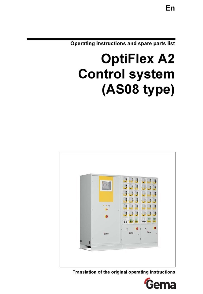
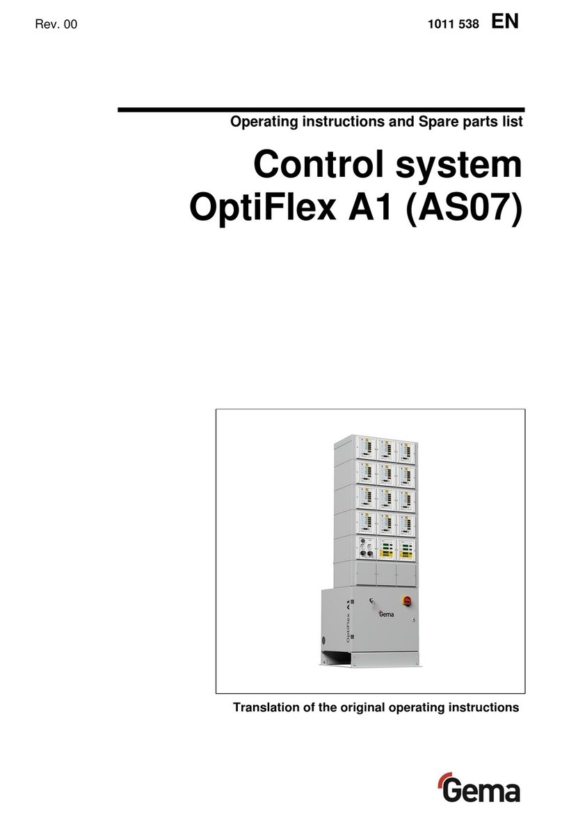
Gema OptiFlex A1 Guide

En
Translation of the original operating instructions
Operating instructions and spare parts list
OptiFlex A1
Control system
(AS07 type)

V 12/13
Documentation - OptiFlex A1 (AS07) Control system
© Copyright 2012 Gema Switzerland GmbH
All rights reserved.
This publication is protected by copyright. Unauthorized copying is
prohibited by law. No part of this publication may be reproduced,
photocopied, translated, stored on a retrieval system or transmitted in
any form or by any means for any purpose, neither as a whole nor
partially, without the express written consent of Gema Switzerland
GmbH.
MagicCompact, MagicCylinder, MagicPlus, MagicControl, OptiFlex,
OptiControl, OptiGun, OptiSelect, OptiStar and SuperCorona are
registered trademarks of Gema Switzerland GmbH.
OptiFlow, OptiCenter, OptiMove, OptiSpeeder, OptiFeed, OptiSpray,
OptiSieve, OptiAir, OptiPlus, OptiMaster, MultiTronic, EquiFlow, Precise
Charge Control (PCC), Smart Inline Technology (SIT) and Digital Valve
Control (DVC) are trademarks of Gema Switzerland GmbH.
All other product names are trademarks or registered trademarks of their
respective holders.
Reference is made in this manual to different trademarks or registered
trademarks. Such references do not mean that the manufacturers
concerned approve of or are bound in any form by this manual. We have
endeavored to retain the preferred spelling of the trademarks, and
registered trademarks of the copyright holders.
To the best of our knowledge and belief, the information contained in this
publication was correct and valid on the date of publication. Gema
Switzerland GmbH makes no representations or warranties with respect
to the contents or use of this publication, and reserves the right to revise
this publication and make changes to its content without prior notice.
For the latest information about Gema products, visit
www.gemapowdercoating.com.
For patent information, see www.gemapowdercoating.com/patents or
www.gemapowdercoating.us/patents.
Printed in Switzerland
Gema Switzerland GmbH
Mövenstrasse 17
9015 St.Gallen
Switzerland
Phone: +41-71-313 83 00
Fax.: +41-71-313 83 83

V 12/13
OptiFlex A1 (AS07) Table of contents •1
Table of contents
General safety regulations 3
Safety symbols (pictograms)...................................................................................3
Proper use...............................................................................................................3
Product-specific safety measures ........................................................................... 4
OptiFlex A1 Control system .......................................................................4
About this manual 5
General information ................................................................................................5
Function description 7
Field of application ..................................................................................................7
Scope of delivery ....................................................................................................7
OptiFlex A1 Control system - components .............................................................8
OptiFlex A1 Control system - possible configurations ............................................9
Automatic equipment without reciprocator.................................................9
Automatic equipment with reciprocator......................................................9
Technical data 11
OptiFlex A1 Control system ..................................................................................11
Electrical data ..........................................................................................11
Pneumatic data ........................................................................................11
Dimensions ..............................................................................................11
Commissioning 13
Set-up and assembly ............................................................................................13
Assembly notes........................................................................................13
OptiFlex A1 Control cabinet ..................................................................... 14
Start-up .................................................................................................................14
General information .................................................................................14
Power supply............................................................................................14
Compressed air........................................................................................15
Spare parts list 17
Ordering spare parts ............................................................................................. 17
OptiFlex A1 control cabinet - spare parts list ........................................................18
OptiFlex A1 control cabinet - spare parts .............................................................19
OptiFlex A1 - Pneumatics (systems without OptiAir CA10) – spare parts list ......20
OptiFlex A1 - Pneumatics (systems without OptiAir CA10) – spare parts............21


V 12/13
OptiFlex A1 (AS07) General safety regulations •3
General safety regulations
This chapter sets out the fundamental safety regulations that must be
followed by the user and third parties using the OptiFlex A1 (AS07)
control system.
These safety regulations must be read and understood in full before the
OptiFlex A1 (AS07) control system is put into operation.
Safety symbols (pictograms)
The following warnings with their meanings can be found in the Gema
Switzerland operating instructions. The general safety precautions must
also be followed as well as the regulations in the operating instructions.
DANGER!
Danger due to electrically live or moving parts. Possible consequences:
death or serious injury
WARNING!
Improper use of the equipment could damage the machine or cause it to
malfunction. Possible consequences: minor injuries or damage to
equipment
INFORMATION!
Useful tips and other information
Proper use
1. The OptiFlex A1 (AS07) control system is built to the latest
specification and conforms to the recognized technical safety
regulations and is designed for the normal application of powder
coating.
2. Any other use is considered non-compliant. The manufacturer
shall not be liable for damage resulting from such use; the user
bears sole responsibility for such actions. If the OptiFlex A1
(AS07) is to be used for other purposes or other substances
outside of our guidelines then Gema Switzerland GmbH should
be consulted.

V 12/13
4 •General safety regulations OptiFlex A1 (AS07)
3. Observance of the operating, service and maintenance
instructions specified by the manufacturer is also part of
conformity of use. The OptiFlex A1 (AS07) should only be used,
maintained and started up by trained personnel, who are
informed about and are familiar with the possible hazards
involved.
4. Start-up (i.e. the execution of a particular operation) is forbidden
until it has been established that the OptiFlex A1 (AS07) has
been set up and wired according to the guidelines for machinery
(2006/42 EG). EN 60204-1 (machine safety) must also be
observed.
5. Unauthorized modifications to the OptiFlex A1 (AS07) exempt
the manufacturer from any liability from resulting damage.
6. The relevant accident prevention regulations, as well as other
generally recognized safety regulations, occupational health and
structural regulations are to be observed.
7. Furthermore, the country-specific safety regulations also must be
observed.
Explosion protection Protection
type Temperature class
II 3D IP54 T6 (zone 21)
T4 (zone 22)
Product-specific safety measures
- Installation work performed by the customer must be carried
out according to local regulations.
- Before starting up the plant a check must be made that no
foreign objects are in the booth or in the ducting (input and
exhaust air)
- All components must be grounded according to the local
regulations before start-up.
OptiFlex A1 Control system
The OptiFlex A1 (AS07) control system is a constituent part of the
equipment and is therefore integrated in the system's safety concept.
If it is to be used in a manner outside the scope of the safety concept,
then corresponding measures must be taken.
NOTE:
For further information, see the more detailed Gema safety
regulations!

V 12/13
OptiFlex A1 (AS07) About this manual •5
About this manual
General information
These operating manual contains all important information which you
require for the working with the OptiFlex A1 (AS07) control
systemOptiFlex-A1-de.doc. It will safely guide you through the start-up
process and give you references and tips for the optimal use of your new
powder coating system.
Information about the functionality of the individual system components -
booth, gun control unit, manual gun or powder injector - should be
referenced to their enclosed corresponding documents.
DANGER:
Working without operating instructions
Working without operating instructions or with individual pages
from the operating instructions may result in damage to property
and personal injury if relevant safety information is not observed.
►Before working with the device, organize the required documents and
read the section "Safety regulations".
►Work should only be carried out in accordance with the instructions of
the relevant documents.
►Always work with the complete original document.


V 12/13
OptiFlex A1 (AS07) Function description •7
Function description
Field of application
The OptiFlex A1 Control system was especially designed to meet the
requirements of production, and also the custom electrostatic coating
requirements.
The flexible, modular structure of the OptiFlex A1 Control system is
readily adaptable to any modifications in the installation.
Scope of delivery
The scope of delivery depends on the type and the number of installed
control units (see therefore chapter "OptiFlex A1 Control system -
components").

V 12/13
8 •Function description OptiFlex A1 (AS07)
OptiFlex A1 Control system - components
OptiFlex A1 control cabinet Function
- Equipment main switch
- Key switch for switching on/off the guns
- Interlocks on the mounting plate
- Max. 15 places for gun or axis control units
- Pneumatic functions by OptiAir CA10
- Option: connectable LM02 Level sensor
OptiStar CG08 Gun control unit Function
- OptiStar CG08 standard gun control unit
- Max. 250 stored programs possible
- DVC (Digital Valve Control)
- PCC (Precise Charge Control)
OptiMove CR07 Axis control unit Function
- Axis control unit for ZA0x Reciprocator
- Pendulum operating mode or sequence programs
- Max. 255 stored programs possible
OptiAir CA10-A/B pneumatic-fluidizing unit Function
- Air distribution for OptiFlex A1 and gun control units
- Airmover control unit
- Fluidization in the powder hopper
- Manual prefluidization
OptiAir CA10-C pneumatic unit Function
- Air distribution for OptiFlex A1 and gun control units
LM02 Level sensor Function
- Level detection in the powder hopper

V 12/13
OptiFlex A1 (AS07) Function description •9
OptiFlex A1 Control system - possible configurations
Automatic equipment without reciprocator
Automatic equipment with reciprocator
Control units Fluidized powder
hopper with injector
and Airmover
Powder
guns
Control units Reciprocator with guns
Fluidized powder
hopper with injector
and Airmover


V 12/13
OptiFlex A1 (AS07) Technical data •11
Technical data
OptiFlex A1 Control system
Electrical data
OptiFlex A1 (AS07)
Main input voltage 100-240 VAC
Device input voltage
100-240 VAC
(for gun control units)
200-240 VAC
(for axis control units)
Frequency 50/60 Hz
Input power (sum of the power values of
all control units)
40 VA per gun control unit
1.1 kVA per axis control unit
Protection type (control units) IP54
Temperature range (operation) 10-40°C / 50-104 °F
Pneumatic data
OptiFlex A1 (AS07)
Min. input pressure 6 bar / 87 psi
Max. input pressure 8 bar / 116 psi
Max. water vapor content of the
compressed air 1.3 g/m³
Max. oil vapor content of the compressed
air 0.1 mg/m³
Total air consumption 8 Nm³/h per gun (plus powder
hopper air requirement)
Dimensions
OptiFlex A1 (AS07)
Width 600 mm
Depth 697 mm
Height max. 1838 mm
NOTE:
Further specifications will be found in the corresponding manuals
of the components!


V 12/13
OptiFlex A1 (AS07) Commissioning •13
Commissioning
Set-up and assembly
Assembly notes
After unpacking and installing the OptiFlex system, the control cabinet is
to be fitted to the floor with the supplied steel bolts. The mounting holes
are located in the Z-profiles on both cabinet sides.
The internal connections have already been made at the factory. The
control unit connections to the external plant parts must be done at the
start-up.
The connection possibilities for the individual control units are found in
the corresponding operating manuals.
When connecting, pay attention particularly to the length and the radii of
the pneumatics hoses!
Set-up and assembly
Compressed ai
r
inpu
t
Main valve
Terminal block
recommended

V 12/13
14 •Commissioning OptiFlex A1 (AS07)
OptiFlex A1 Control cabinet
Combination examples:
- 1 OptiAir with max. 15 OptiStar control units
- 1 OptiAir with 2 OptiMove and 13 OptiStar control units
Start-up
General information
These general information serves to obtain an overview of the possible
OptiFlex A1 system combinations.
Detailed information will be found in the corresponding operating
manuals!
Power supply
- As mains supply, a single phase alternating current is
required
- If the OptiStar CG08 gun control unit is used, it can be
connected to tensions of 100-240 VAC
- If the OptiMove reciprocator control unit is used, a mains
voltage of 230 VAC must be available
- Frequencies of 50 or 60 Hz can be used
- The input power value is evident in the technical data
section
- All electrical components are implemented in accordance
to IP54 protection type regulations

V 12/13
OptiFlex A1 (AS07) Commissioning •15
NOTE:
The OptiFlex A1 powder coating control system may can be
switched on only if the booth is in operation!
If the booth switches off, the control system must also switch off!
Compressed air
- The OptiAir pneumatic-fluidizing unit is always used as
main compressed air input, compressed air distributor
and for fluidizing air monitoring
- The OptiFlex A1 Control system just requires a
connection to the main compressed air system
- The compressed air values are evident in the technical
data section
Air requirement with increased powder output
The control system offers the possibility to work with increased powder
output in sufficiently dimensioned compressed air systems. The pressure
regulator on the filter unit is preset by factory to 5.5 bar with an air flow of
5 m3/h per control unit. If another value is set on the pressure regulator,
then the system parameter 2 on each OptiStar Control unit needs to be
adjusted according to the following instructions:
NOTE:
In order to achieve the largest accuracy, the air pressure is to be set
during operation by average compressed air consumption!
> 5 s
Compressed air setting - parameter setting
O
p
tiStar CG08 automatic
g
un control unit
Conversion bar-psi
5.5 bar = 80 psi
6.0 bar = 87 psi
6.5 bar = 94 psi
5.5 6.0
6.5


V 12/13
OptiFlex A1 (AS07) Spare parts list •17
Spare parts list
Ordering spare parts
When ordering spare parts for powder coating equipment, please indicate
the following specifications:
- Type and serial number of your powder coating
equipment
- Order number, quantity and description of each spare
part
Example:
- Type OptiFlex A1 (AS07)
Serial number 1234 5678
- Order no. 203 386, 1 piece, Clamp - Ø 18/15 mm
When ordering cable or hose material, the required length must also be
given. The spare part numbers of this bulk stock is always marked with
an *.
Wearing parts are always marked with a #.
All dimensions of plastic hoses are specified with the external and
internal diameter:
Example:
Ø 8/6 mm, 8 mm outside diameter (o/d) / 6 mm inside diameter (i/d)
WARNING!
Only original Gema spare parts should be used, because the
explosion protection will also be preserved that way. The use of
spare parts from other manufacturers will invalidate the Gema
guarantee conditions!

V 12/13
18 •Spare parts list OptiFlex A1 (AS07)
OptiFlex A1 control cabinet - spare parts list
1 OptiStar CG08 Gun control unit - see corresponding operating manual
2 OptiMove CR07 Axis control unit - see corresponding operating manual
3 OptiAir CA10-A Pneumatic-fluidizing unit - see corresponding operating manual
OptiAir CA10-B Pneumatic-fluidizing unit - see corresponding operating manual
Pneumatic unit (systems without OptiAir CA10) - see corresponding spare parts list
4 Main switch – see enclosed wiring diagram
5 Key switch – see enclosed wiring diagram
6 Lock - complete 262 110
Plate (for pos. 6, not shown) 262 145
Key (for pos. 6, not shown) 259 908
7 Roof 1008 813
8 Standard module 1008 806
9 Support 1007 873
10 Crossbeam 1008 812
11 Mounting plate, system-dependent – see enclosed wiring diagram
NOTE:
Further specifications will be found in the corresponding manuals
and spare parts list of the components!
Other manuals for OptiFlex A1
1
This manual suits for next models
1
Table of contents
Other Gema Control System manuals