Gemalto Cinterion EMS31-V Installation guide

GEMALTO.COM/M2M
Cinterion®EMS31-V
Hardware Interface Overview
Version: 00.004
DocId: EMS31_V_HIO_v00.004

GENERAL NOTE
THE USE OF THE PRODUCT INCLUDING THE SOFTWARE AND DOCUMENTATION (THE "PROD-
UCT") IS SUBJECT TO THE RELEASE NOTE PROVIDED TOGETHER WITH PRODUCT. IN ANY
EVENT THE PROVISIONS OF THE RELEASE NOTE SHALL PREVAIL. THIS DOCUMENT CONTAINS
INFORMATION ON GEMALTO M2M PRODUCTS. THE SPECIFICATIONS IN THIS DOCUMENT ARE
SUBJECT TO CHANGE AT GEMALTO M2M'S DISCRETION. GEMALTO M2M GMBH GRANTS A NON-
EXCLUSIVE RIGHT TO USE THE PRODUCT. THE RECIPIENT SHALL NOT TRANSFER, COPY,
MODIFY, TRANSLATE, REVERSE ENGINEER, CREATE DERIVATIVE WORKS; DISASSEMBLE OR
DECOMPILE THE PRODUCT OR OTHERWISE USE THE PRODUCT EXCEPT AS SPECIFICALLY
AUTHORIZED. THE PRODUCT AND THIS DOCUMENT ARE PROVIDED ON AN "AS IS" BASIS ONLY
AND MAY CONTAIN DEFICIENCIES OR INADEQUACIES. TO THE MAXIMUM EXTENT PERMITTED
BY APPLICABLE LAW, GEMALTO M2M GMBH DISCLAIMS ALL WARRANTIES AND LIABILITIES.
THE RECIPIENT UNDERTAKES FOR AN UNLIMITED PERIOD OF TIME TO OBSERVE SECRECY
REGARDING ANY INFORMATION AND DATA PROVIDED TO HIM IN THE CONTEXT OF THE DELIV-
ERY OF THE PRODUCT. THIS GENERAL NOTE SHALL BE GOVERNED AND CONSTRUED
ACCORDING TO GERMAN LAW.
Copyright
Transmittal, reproduction, dissemination and/or editing of this document as well as utilization of its con-
tents and communication thereof to others without express authorization are prohibited. Offenders will be
held liable for payment of damages. All rights created by patent grant or registration of a utility model or
design patent are reserved.
Copyright © 2018, Gemalto M2M GmbH, a Gemalto Company
Trademark Notice
Gemalto, the Gemalto logo, are trademarks and service marks of Gemalto and are registered in certain
countries. Microsoft and Windows are either registered trademarks or trademarks of Microsoft Corpora-
tion in the United States and/or other countries. All other registered trademarks or trademarks mentioned
in this document are property of their respective owners.
EMS31_V_HIO_v00.004 2018-02-27
Confidential / Preliminary
Cinterion®EMS31-V Hardware Interface Overview
2
Page 2 of 35
Document Name: Cinterion®EMS31-V Hardware Interface Overview
Version: 00.004
Date: 2018-02-27
DocId: EMS31_V_HIO_v00.004
Status: Confidential / Preliminary

Cinterion®EMS31-V Hardware Interface Overview
Contents
35
EMS31_V_HIO_v00.004 2018-02-27
Confidential / Preliminary
Page 3 of 100
Contents
1 Introduction.................................................................................................................6
1.1 Key Features at a Glance .................................................................................. 6
1.2 EMS31-V System Overview............................................................................... 8
2 Interface Characteristics............................................................................................9
2.1 Application Interface .......................................................................................... 9
2.1.1 Serial Interface ASC0 ........................................................................... 9
2.1.2 Serial Interface ASC1 ......................................................................... 10
2.1.3 UICC/SIM/USIM Interface................................................................... 11
2.1.4 GPIO Interface .................................................................................... 13
2.1.5 Control Signals.................................................................................... 14
2.1.5.1 Status LED .......................................................................... 14
2.1.5.2 Fast Shutdown .................................................................... 14
2.2 RF Antenna Interface....................................................................................... 15
2.2.1 Antenna Instalation ............................................................................. 16
2.3 Sample Application .......................................................................................... 17
3 Operating Characteristics........................................................................................19
3.1 Operating Modes ............................................................................................. 19
3.2 Power Supply................................................................................................... 19
4 Mechanical Dimensions, Mounting and Packaging...............................................20
4.1 Mechanical Dimensions of EMS31-V............................................................... 20
5 Regulatory and Type Approval Information...........................................................22
5.1 Directives and Standards................................................................................. 22
5.2 SAR requirements specific to portable mobiles ............................................... 24
5.3 Reference Equipment for Type Approval......................................................... 25
5.4 Compliance with FCC and Regulations ........................................................... 26
6 Document Information..............................................................................................28
6.1 Revision History ............................................................................................... 28
6.2 Related Documents ......................................................................................... 29
6.3 Terms and Abbreviations ................................................................................. 29
6.4 Safety Precaution Notes .................................................................................. 33
7 Appendix....................................................................................................................34
7.1 List of Parts and Accessories........................................................................... 34

Cinterion®EMS31-V Hardware Interface Overview
Tables
35
EMS31_V_HIO_v00.004 2018-02-27
Confidential / Preliminary
Page 4 of 100
Tables
Table 1: Signals of the SIM interface (SMT application interface) ............................... 11
Table 2: GPIO lines and possible alternative assignment............................................ 13
Table 3: RF Antenna interface parameters.................................................................. 15
Table 4: RF Antenna interface parameters.................................................................. 15
Table 5: Overview of operating modes ........................................................................ 19
Table 6: Directives ....................................................................................................... 22
Table 7: Standards of North American type approval .................................................. 22
Table 8: Standards of Verizon type approval............................................................... 22
Table 9: Standards of GCF and PTCRB type approval ............................................... 22
Table 10: Requirements of quality ................................................................................. 22
Table 11: Standards of the Ministry of Information Industry of the
People’s Republic of China............................................................................ 23
Table 12: Toxic or hazardous substances or elements with defined concentration
limits............................................................................................................... 23
Table 13: Antenna gain limits for FCC ........................................................................... 26
Table 14: List of parts and accessories.......................................................................... 34
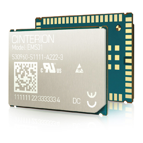
Table 15: Molex sales contacts (subject to change) ...................................................... 34
Cinterion®EMS31-V Hardware Interface Overview
Figures
35
EMS31_V_HIO_v00.004 2018-02-27
Confidential / Preliminary
Page 5 of 35
Figures
Figure 1: EMS31-V system overview .............................................................................. 8
Figure 2: Serial interface ASC0....................................................................................... 9
Figure 3: Serial interface ASC1..................................................................................... 10
Figure 4: External UICC/SIM/USIM card holder circuit ................................................. 12
Figure 5: Schematic diagram of EMS31-V sample application ..................................... 18
Figure 6: EMS31-V - top and bottom view .................................................................... 20
Figure 7: Dimensions of EMS31-V (all dimensions in mm)........................................... 21
Figure 8: Dimensions of EMS31-V (all dimensions in mm) - bottom view..................... 21
Figure 9: Reference equipment for Type Approval ....................................................... 25

Cinterion®EMS31-V Hardware Interface Overview
1 Introduction
8
EMS31_V_HIO_v00.004 2018-02-27
Confidential / Preliminary
Page 6 of 35
1 Introduction
This document1describes the hardware of the Cinterion®EMS31-V module for Verizon Net-
work. It helps you quickly retrieve interface specifications, electrical and mechanical details and
information on the requirements to be considered for integrating further components.
The EMS31-V module includes a baseband, a complete dual band RF front-end, memory and
required circuitry to meet the 3GPP E-UTRA Long Term Evolution - LTE, Release 13 CAT M1
set of specifications.
1.1 Key Features at a Glance
1. The document is effective only if listed in the appropriate Release Notes as part of the technical docu-
mentation delivered with your Gemalto M2M product.
Feature Implementation
General
Frequency bands • Band 4, AWS (1700/2100 MHz) (LTE HD-FDD)
• Band 13, 700 MHz (LTE HD-FDD)
Output power Class 3 (+23dBm +-2dB) for LTE AWS, LTE B4
Class 3 (+23dBm +-2dB) for LTE 700, LTE FDD B13
Power supply 3.2V to 5.5V
Operating temperature
(board temperature)
Normal operation: -30°C to +85°C
Extended operation: -40°C to +95°C
Physical Dimensions: 27.60mm x 18.80mm x 2.05mm
Weight: approx. 2.2g
RoHS All hardware components fully compliant with EU RoHS Directive
LTE features
3GPP Release 13 DL 300 kbps, UL 375 kbps
LTE Cat. M1 data rates
SMS Point-to-point MT and MO
Text mode
Storage in mobile equipment
Software
AT commands Hayes, 3GPP TS 27.007, TS 27.005, product specific
SIM Application Toolkit SAT Release 99
Firmware update Generic update from host application over ASC0
OTA over ASC0

Cinterion®EMS31-V Hardware Interface Overview
1.1 Key Features at a Glance
8
EMS31_V_HIO_v00.004 2018-02-27
Confidential / Preliminary
Page 7 of 35
Interfaces
Module interface Surface mount device with solderable connection pads (SMT application
interface). Land grid array (LGA) technology ensures high solder joint reli-
ability and allows the use of an optional module mounting socket.
For more information on how to integrate SMT modules see also [3]. This
application note comprises chapters on module mounting and application
layout issues as well as on SMT application development equipment.
2 serial interfaces ASC0:
• 8-wire modem interface with status and control lines, unbalanced, asyn-
chronous
• Default baud rate: 115,200 baud
• Adjustable baud rates: 1,200 to 3,686,400
• Supports RTS0/CTS0 hardware flow control.
• Indication of incoming data/SMS on RING0 (can be used to wake up
host from power down modes)
ASC1 (shared with GPIO lines):
• 4-wire, unbalanced asynchronous interface
• Default baud rate: 115,200 baud
• Adjustable baud rates: 1,200 to 3,686,400bps
• Supports RTS1/CTS1 hardware flow control
UICC interface Supported SIM/USIM cards: 3V, 1.8V
Embedded UICC Module is hardware prepared for an embedded UICC (MIM)
GPIO interface 20 pads of the application interface programmable as GPIO pads:
GPIOs can be configured as ASC0 and ASC1
Programming is done via AT commands
Antenna interface pad 50ΩLTE antenna
Power on/off, Reset
Power on/off Switch-on by hardware signal ON
Switch-off by AT command
Automatic switch-off in case of critical temperature and voltage conditions
Reset Orderly shutdown and reset by AT command
Evaluation kit
Evaluation module EMS31-V module soldered onto a dedicated PCB that can be connected to
an adapter in order to be mounted onto the DSB75.
DSB75 DSB75 Development Support Board designed to test and type approve
Gemalto M2M modules and provide a sample configuration for application
engineering. A special adapter is required to connect the EMS31-V evalua-
tion module to the DSB75.
Feature Implementation

Cinterion®EMS31-V Hardware Interface Overview
1.2 EMS31-V System Overview
8
EMS31_V_HIO_v00.004 2018-02-27
Confidential / Preliminary
Page 8 of 35
1.2 EMS31-V System Overview
Note: The following features are not yet available with the current product release: GPIO, I2C, Pulse Count-
er, PWM, SPI, ADC and 2nd SIM/MIM. Second SIM/MIM interface is hardware prepared only.
Figure 1: EMS31-V system overview
GPIO
interface
I2C
ASC0
CONTROL
POWER
ANTENNA
(LTE band)
Module
SIM1 interface
(with SIM detection)
SIM1
Application
BATT+
V180
VCORE
Emergency reset
ON
Serial modem
interface
I2C
4
4
1
1
1
Antenna
1
7
Status LED
1
FST_SHDN Fast shutdown
1
1
ADC ADC
1
COUNTER
PWM
1
GP(I)Os
SPI SPI
2
ASC1 Serial interface
4
5
1
SIM2 interface/MIM
(with SIM detection)
SIM2 /MIM
1
5
PWM
4
4
Pulse Counter
1
1
1
2
3
2
1
1
1

Cinterion®EMS31-V Hardware Interface Overview
2 Interface Characteristics
18
EMS31_V_HIO_v00.004 2018-02-27
Confidential / Preliminary
Page 9 of 35
2 Interface Characteristics
EMS31-V is equipped with an SMT application interface that connects to the external applica-
tion. The SMT application interface incorporates the various application interfaces as well as
the RF antenna interfaces.
2.1 Application Interface
2.1.1 Serial Interface ASC0
EMS31-V offers an 8-wire unbalanced, asynchronous modem interface ASC0 conforming to
ITU-T V.28 protocol DCE signaling. The electrical characteristics do not comply with ITU-T
V.28. The significant levels are 0V (for low data bit or active state) and 1.8V (for high data bit
or inactive state).
EMS31-V is designed for use as a DCE. Based on the conventions for DCE-DTE connections
it communicates with the customer application (DTE) using the following signals:
• Port TXD @ application sends data to the module’s TXD0 signal line
• Port RXD @ application receives data from the module’s RXD0 signal line
Figure 2: Serial interface ASC0
Features:
• Includes the data lines TXD0 and RXD0, the status lines RTS0 and CTS0 and, in addition,
the modem control lines DTR0, DSR0, DCD0 and RING0.
• Configured for 8 data bits, no parity and 1 stop bit.
• ASC0 can be operated at fixed bit rates from 1,200bps up to 3,686,400bps.
• Autobauding (supported by future firmware version)
• Supports RTS0/CTS0 hardware flow control. Communication is possible only by respecting
hardware flow control. Otherwise, the module might disregard some data transmitted from
host.
• Wake up from SLEEP mode by RTS0 activation.

Cinterion®EMS31-V Hardware Interface Overview
2.1 Application Interface
18
EMS31_V_HIO_v00.004 2018-02-27
Confidential / Preliminary
Page 10 of 35
2.1.2 Serial Interface ASC1
EMS31-V provides a 4-wire unbalanced, asynchronous modem interface ASC1 conforming to
ITU-T V.24 protocol DCE signaling. The electrical characteristics do not comply with ITU-T
V.28. The significant levels are 0V (for low data bit or active state) and 1.8V (for high data bit
or inactive state).
EMS31-V is designed for use as a DCE. Based on the conventions for DCE-DTE connections
it communicates with the customer application (DTE) using the following signals:
• Port TXD @ application sends data to module’s TXD1 signal line
• Port RXD @ application receives data from the module’s RXD1 signal line
Figure 3: Serial interface ASC1
Features
• Includes only the data lines TXD1 and RXD1 plus RTS1 and CTS1 for hardware hand-
shake.
• On ASC1 no RING line is available.
• Configured for 8 data bits, no parity and 1 or 2 stop bits.
• ASC1 can be operated at fixed bit rates from 1,200 bps to 3,686,400bps.
• Supports RTS1/CTS1 hardware flow control. Communication is possible only by respecting
hardware flow control. Otherwise, the module might disregard some data transmitted from
host.
• Wake up from SLEEP mode by RTS1 activation.
TXD1
RXD1
RTS1
CTS1
TXD
RXD
RTS
CTS
Module(DCE) Application (DCE)

Cinterion®EMS31-V Hardware Interface Overview
2.1 Application Interface
18
EMS31_V_HIO_v00.004 2018-02-27
Confidential / Preliminary
Page 11 of 35
2.1.3 UICC/SIM/USIM Interface
EMS31-V has two identical integrated UICC/SIM/USIM interfaces compatible with the 3GPP
31.102 and ETSI 102 221. These two interfaces are mutually exclusive, meaning that only one
UICC/SIM/USIM interface can be used at a time. This interface is wired to the host interface in
order to be connected to an external SIM card holder. Five pads on the SMT application inter-
face are reserved for each SIM interface.
The UICC/SIM/USIM interface supports 3V and 1.8V SIM cards.
The CCINx signal serves to detect whether a tray (with SIM card) is present in the card holder.
The CCINx signal must be connected to V180 for the detection to work on the module. Other-
wise the SIM card can never be detected by the module.
Using the CCINx signal is mandatory for compliance with the GSM 11.11 recommendation if
the mechanical design of the host application allows the user to remove the SIM card during
operation. To take advantage of this feature, an appropriate SIM card detect switch is required
on the card holder. For example, this is true for the model supplied by Molex, which has been
tested to operate with EMS31-V and is part of the Gemalto M2M reference equipment submit-
ted for type approval. See Section 7.1 for Molex ordering numbers.
Note: No guarantee can be given, nor any liability accepted, if loss of data is encountered after
removing the SIM card during operation. Also, no guarantee can be given for properly initializ-
ing any SIM card that the user inserts after having removed the SIM card during operation. In
this case, the application must restart EMS31-V.
Table 1: Signals of the SIM interface (SMT application interface)
Signal Description
GND Separate ground connection for SIM card to improve EMC.
CCCLKx Chipcard clock
CCVCCx SIM supply voltage.
CCIOx Serial data line, input and output.
CCRSTx Chipcard reset
CCINx Input on the baseband processor for detecting a SIM card tray in the holder. If the SIM is
removed during operation the SIM interface is shut down immediately to prevent destruc-
tion of the SIM. The CCINx signal is by default low and will change to high level if a SIM
card is inserted.
The CCINx signal is mandatory for applications that allow the user to remove the SIM card
during operation.
The CCINx signal is solely intended for use with a SIM card. It must not be used for any
other purposes. Failure to comply with this requirement may invalidate the type approval of
EMS31-V.
Pull-down 220k resistor is mandatory.

Cinterion®EMS31-V Hardware Interface Overview
2.1 Application Interface
18
EMS31_V_HIO_v00.004 2018-02-27
Confidential / Preliminary
Page 12 of 35
The figure below shows a circuit to connect an external SIM card holder.
Figure 4: External UICC/SIM/USIM card holder circuit
The total cable length between the SMT application interface pads on EMS31-V and the pads
of the external SIM card holder must not exceed 100mm in order to meet the specifications of
3GPP TS 51.010-1 and to satisfy the requirements of EMC compliance.
To avoid possible cross-talk from the CCCLKx signal to the CCIOx signal be careful that both
lines are not placed closely next to each other. A useful approach is using a GND line to shield
the CCIOx line from the CCCLKx line.
SIM
CCVCC
CCRST
CCIO
CCCLK
220nF
1nF
CCIN
V180
R 220k
Switch position (SIM inserted )
Switch position(SIM
not inserted)
4k7

Cinterion®EMS31-V Hardware Interface Overview
2.1 Application Interface
18
EMS31_V_HIO_v00.004 2018-02-27
Confidential / Preliminary
Page 13 of 35
2.1.4 GPIO Interface
EMS31-V offers a GPIO interface with 20 GPIO lines. The lines are shared with other interfaces
or functions: ASC0 (see Section 2.1.1), ASC1 (see Section 2.1.2), status LED (see Section
2.1.5.1), Fast shutdown (see Section 2.1.5.2),
The following table shows the configuration variants for the GPIO pads. All variants are mutu-
ally exclusive, i.e. a pad configured for instance as ASC0 is locked for alternative usage.
*) Note: The following features are not yet available with the current product release: GPIO, I2C, Pulse
Counter, PWM and SPI.
After startup, the above mentioned alternative GPIO line assignments can be configured using
AT commands (see [1]). The configuration is non-volatile and available after module restart.
Table 2: GPIO lines and possible alternative assignment
GPIO* Fast
Shut-
down
Status
LED Pulse
Counter* ASC0 ASC1 SPI* PWM* WAKE
capability
GPIO1 DTR0 Available
GPIO2 DCD0
GPIO3 DSR0
GPIO4 FST_SHD
N
GPIO5 LED
GPIO6 PWM2
GPIO7 PWM1
GPIO8 COUNTER Available
GPIO16 RXD1
GPIO17 TXD1
GPIO18 RTS1 Available
GPIO19 CTS1
GPIO20
GPIO21
GPIO22
GPIO23
GPIO24 RING0 Available
GPIO25 Available
GPIO26 SPI_CS
1
GPIO27 SPI_CS
2
n/a RST0 Available

Cinterion®EMS31-V Hardware Interface Overview
2.1 Application Interface
18
EMS31_V_HIO_v00.004 2018-02-27
Confidential / Preliminary
Page 14 of 35
2.1.5 Control Signals
2.1.5.1 Status LED
The LED line can also be configured as GPIO5 line, and can be used to drive a status LED that
indicates different operating modes of the module (for GPIOs see Section 2.1.4). LED and
GPIO5 functionality are mutually exclusive.
2.1.5.2 Fast Shutdown
The GPIO4 interface line can be configured as fast shutdown signal line FST_SHDN. The con-
figured FST_SHDN line is an active low control signal.

Cinterion®EMS31-V Hardware Interface Overview
2.2 RF Antenna Interface
18
EMS31_V_HIO_v00.004 2018-02-27
Confidential / Preliminary
Page 15 of 35
2.2 RF Antenna Interface
The RF interface has an impedance of 50Ω. EMS31-V RF pads are located on pads 58, 59 and
60 (pad 59 is RF_out pad, and pads 58 and 60 are GND pads). The antenna interface is typi-
cally connected by soldering it directly to the application’s PCB.
The antenna interface is designed to meet signal levels according to 3GPP specification.
EMS31-V is capable of sustaining a 10:1 voltage standing wave ratio (VSWR) mismatch at the
antenna line without any damage, even when transmitting at maximum RF power. Antenna pad
is the antenna reference point (ARP) for EMS31-V. All RF data specified throughout this doc-
ument is related to ARP.
Note that DC blocking caps are needed in case DC is applied.
EMS31-V operates in the following frequency bands:
• Band 4, AWS (1700/2100 MHz) (LTE HD-FDD)
• Band 13, 700 MHz (LTE HD-FDD)
The following table provides basic information about RF parameters:
.
Please be aware that, in TS 36.521-1, Table 7.3.5-1, the power level is PREFSENS. This has a
fixed relationship with the RS EPRE (reference signal energy per resource element), which is:
PREFSENS = RS EPRE + 10 * log10(N_RE),
where N_RE is the number of resource elements (12 *[number of RBs]).
Table 4: RF Antenna interface parameters
Parameter Conditions Typical Unit
Sensitivity LTE Band 4 -1061
1. The value is valid for 6RB in all possible BW (5, 10, 15, 20MHz)
dBm
LTE Band 13 -1061dBm
RF Power @ ARP LTE Band 4 232
2. Absolute maximum rating of RF peak power is <27.5 dBm
dBm
LTE Band 13 232dBm
Receiver return loss in
used band
LTE Band 4 >103
3. EMS31-V is HD-FDD, what means that the return loss at RX band could be <5dB during transmission
dB
LTE Band 13 >103dB

Cinterion®EMS31-V Hardware Interface Overview
2.2 RF Antenna Interface
18
EMS31_V_HIO_v00.004 2018-02-27
Confidential / Preliminary
Page 16 of 35
2.2.1 Antenna Instalation
The distance between the antenna RF pads and its neighboring GND pads has been optimized
for best possible impedance. On the application PCB, special attention should be paid to these
3 pads, in order to prevent mismatch.
The wiring of the antenna connection line, starting from the antenna pad to the application an-
tenna should result in a 50Ωline impedance. Line width and distance to the GND plane needs
to be optimized with regard to the PCB’s layer stack.
To prevent receiver desensitization due to interferences generated by fast transients like high
speed clocks on the application PCB, it is recommended to realize the antenna connection line
using uninterrupted ground plane and embedded Stripline rather than Microstrip line technolo-
gy.
For type approval purposes (i.e., FCC KDB 996369 related to modular approval requirements)
an external application must connect the RF signal in one of the following ways:
•Via50
Ωcoaxial antenna connector (common connectors are U-FL or SMA) placed as close
as possible to the module's antenna pad.
• By soldering the antenna to the antenna connection line on the application’s PCB (without
the use of any connector) as close as possible to the module’s antenna pad.
• By routing the application PCB's antenna to the module’s antenna pad in the shortest way.
Awareness for ESD protection on the RF interfaces should also be considered. This
protection could be utilized through the pi-network above (primarily for managing any
additional RF optimization needs) or by additional component addition in series with the above
pi-network matching.

Cinterion®EMS31-V Hardware Interface Overview
2.3 Sample Application
18
EMS31_V_HIO_v00.004 2018-02-27
Confidential / Preliminary
Page 17 of 35
2.3 Sample Application
Figure 5 shows a typical example of how to integrate an EMS31-V module with an application.
Usage of the various host interfaces depends on the desired features of the application.
Because of the high RF field density inside the module, it cannot be guaranteed that no self
interference might occur, depending on frequency and the applications grounding concept. The
potential interferers may be minimized by placing small capacitors (47pF) at suspected lines
(e.g. RXD0, or ON).
While developing SMT applications it is strongly recommended to provide test points
for certain signals, i.e., lines to and from the module - for debug and/or test purposes.
The SMT application should allow for an easy access to these signals. For details on
how to implement test points see [3].
The EMC measures are best practice recommendations. In fact, an adequate EMC strategy for
an individual application is very much determined by the overall layout and, especially, the po-
sition of components.
Note: EMS31-V is not intended for use with cables longer than 3m.
Disclaimer: No warranty, either stated or implied, is provided on the sample schematic diagram
shown in Figure 5 and the information detailed in this section. As functionality and compliance
with national regulations depend to a great amount on the used electronic components and the
individual application layout manufacturers are required to ensure adequate design and oper-
ating safeguards for their products using EMS31-V module.

Cinterion®EMS31-V Hardware Interface Overview
2.3 Sample Application
18
EMS31_V_HIO_v00.004 2018-02-27
Confidential / Preliminary
Page 18 of 35
Note: The following features are not yet available with the current product release: GPIO, I2C, Pulse Count-
er, PWM, SPI, ADC and 2nd SIM/MIM. Second SIM/MIM interface is hardware prepared only.
Figure 5: Schematic diagram of EMS31-V sample application
EMS31-V
Antenna
BATT+
GPIOs
LED
COUNTER
PWMs
I2CCLK
I2CDAT
GND
V180
CCIN
CCVCC
CCIO
CCRST
CCCLK
V180
CCIN2
CCVCC2
CCIO2
CCRST2
CCCLK2
ON
FST_SHDN
ASC0
ASC1
Power Supply
47µF47µF100pF
2k2 2k2
V180
µC
SIM2
220nF 10pF
1nF
10pF
R220k 4k7
SIM1
220nF 10pF
1nF
10pF
R220k 4k7

Cinterion®EMS31-V Hardware Interface Overview
3 Operating Characteristics
19
EMS31_V_HIO_v00.004 2018-02-27
Confidential / Preliminary
Page 19 of 35
3 Operating Characteristics
3.1 Operating Modes
The table below briefly summarizes the various operating modes referred to throughout the
document.
3.2 Power Supply
The power supply of EMS31-V has to be a single voltage source at BATT+. It must be able to
provide the current for all operation modes of the module.
All the key functions for supplying power to the device are handled by the power management
section of the analog controller. This IC provides the following features:
• Stabilizes the supply voltages for the baseband using low drop linear voltage regulators and
a DC-DC step down switching regulator.
• Switches the module's power voltages for the power-up and -down procedures.
• SIM switch to provide SIM power supply.
Table 5: Overview of operating modes
Mode Function
Normal
opera-
tion
Active TX LTE data transfer in progress. Power consumption depends on network
settings, data transfer rate and radio conditions.
No data transfer is in progress and no active communication via ASC0/
ASC1.
IDLE No data transfer is in progress. The LTE part of the device can be in
LTE DRX, LTE eDRX or LTE PSM mode. Activity on ASC0 /ASC1 inter-
faces can be present. Power consumption depends on the LTE power
saving mode and its parameters and on the activity on the ASC inter-
faces.
Sleep The module is in low power consumption state. There is no activity inside the module but
module preserves the state in which it was before entering the sleep mode, including the
electrical states of the GPIOs. The module will enter sleep state only when the LTE part of
the module is in LTE DRX, LTE eDRX or LTE PSM mode or if it is in airplane mode. To
allow sleep mode the host application shall indicate via RTS lines that it has no intention to
send data.
Power
Down
Normal shutdown after sending the power down command. Software is not active. Inter-
faces are not accessible. Operating voltage remains applied.
Airplane
mode
Airplane mode shuts down the radio part of the module, causes the module to log off from
the LTE network and disables all AT commands whose execution requires a radio connec-
tion.
Airplane mode can be controlled by AT command (see [1]).
Sleep mode can be entered when airplane mode is enabled.

Cinterion®EMS31-V Hardware Interface Overview
4 Mechanical Dimensions, Mounting and Packaging
21
EMS31_V_HIO_v00.004 2018-02-27
Confidential / Preliminary
Page 20 of 35
4 Mechanical Dimensions, Mounting and Packaging
The following sections describe the mechanical dimensions of EMS31-V and give recommen-
dations for integrating EMS31-V into the host application.
4.1 Mechanical Dimensions of EMS31-V
Figure 6 shows the top and bottom view of EMS31-V and provides an overview of the board's
mechanical dimensions. For further details see Figure 7.
Figure 6: EMS31-V - top and bottom view
Product label
Top view
Bottom view
Table of contents
Other Gemalto Control Unit manuals

Gemalto
Gemalto Cinterion BGS2-W miniPCIe User manual

Gemalto
Gemalto Cinterion EMS31-US Installation guide

Gemalto
Gemalto Cinterion ELS81-US User manual

Gemalto
Gemalto Cinterion EHS6 Installation instructions

Gemalto
Gemalto Cinterion ALAS5 User manual

Gemalto
Gemalto Cinterion EMS31 User manual

Gemalto
Gemalto SafeNet ProtectServer Operator's manual