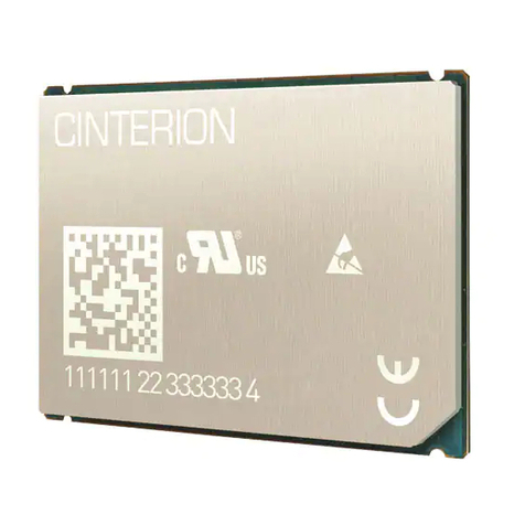
Gemalto Cinterion BGS2-W miniPCIe User manual

BGS2-W miniPCIe
Version: 01.000
DocId: BGS2-W_miniPCIe_v01.000
Hardware Interface Description

GENERAL NOTE
THE USE OF THE PRODUCT INCLUDING THE SOFTWARE AND DOCUMENTATION (THE "PROD-
UCT") IS SUBJECT TO THE RELEASE NOTE PROVIDED TOGETHER WITH PRODUCT. IN ANY
EVENT THE PROVISIONS OF THE RELEASE NOTE SHALL PREVAIL. THIS DOCUMENT CONTAINS
INFORMATION ON CINTERION PRODUCTS. THE SPECIFICATIONS IN THIS DOCUMENT ARE SUB-
JECT TO CHANGE AT CINTERION'S DISCRETION. CINTERION WIRELESS MODULES GMBH
GRANTS A NON-EXCLUSIVE RIGHT TO USE THE PRODUCT. THE RECIPIENT SHALL NOT TRANS-
FER, COPY, MODIFY, TRANSLATE, REVERSE ENGINEER, CREATE DERIVATIVE WORKS; DISAS-
SEMBLE OR DECOMPILE THE PRODUCT OR OTHERWISE USE THE PRODUCT EXCEPT AS
SPECIFICALLY AUTHORIZED. THE PRODUCT AND THIS DOCUMENT ARE PROVIDED ON AN "AS
IS" BASIS ONLY AND MAY CONTAIN DEFICIENCIES OR INADEQUACIES. TO THE MAXIMUM
EXTENT PERMITTED BY APPLICABLE LAW, CINTERION WIRELESS MODULES GMBH DISCLAIMS
ALL WARRANTIES AND LIABILITIES. THE RECIPIENT UNDERTAKES FOR AN UNLIMITED PERIOD
OF TIME TO OBSERVE SECRECY REGARDING ANY INFORMATION AND DATA PROVIDED TO HIM
IN THE CONTEXT OF THE DELIVERY OF THE PRODUCT. THIS GENERAL NOTE SHALL BE GOV-
ERNED AND CONSTRUED ACCORDING TO GERMAN LAW.
Copyright
Transmittal, reproduction, dissemination and/or editing of this document as well as utilization of its con-
tents and communication thereof to others without express authorization are prohibited. Offenders will be
held liable for payment of damages. All rights created by patent grant or registration of a utility model or
design patent are reserved.
Copyright © 2012, Cinterion Wireless Modules GmbH
Trademark Notice
Microsoft and Windows are either registered trademarks or trademarks of Microsoft Corporation in the
United States and/or other countries. PCI, PCI Express, PCIe, and PCI-SIG are trademarks or registered
trademarks of PCI-SIG. All other registered trademarks or trademarks mentioned in this document are
property of their respective owners.
BGS2-W_miniPCIe_v01.000 Page 2 of 36 2012-10-05
Confidential / Preliminary
BGS2-W miniPCIe Hardware Interface Description
2
Document Name: BGS2-W miniPCIe Hardware Interface Description
Version: 01.000
Date: 2012-10-05
DocId: BGS2-W_miniPCIe_v01.000
Status Confidential / Preliminary

BGS2-W miniPCIe Hardware Interface Description
Contents
36
BGS2-W_miniPCIe_v01.000 Page 3 of 36 2012-10-05
Confidential / Preliminary
Contents
0 Document History...................................................................................................... 6
1 Introduction.................................................................................................................7
1.1 Ordering Information..........................................................................................7
1.2 Related Documents ...........................................................................................7
1.3 Terms and Abbreviations...................................................................................7
2 Product Concept.........................................................................................................9
2.1 Key Features at a Glance................................................................................10
2.2 System Overview.............................................................................................12
2.3 Mechanical Dimensions...................................................................................12
3 Application Connector Interface..............................................................................13
3.1 Pin Assignments and Electrical Description.....................................................13
3.2 Characteristics.................................................................................................16
3.2.1 Power Supply and Ground..................................................................16
3.2.2 USB Interface......................................................................................16
3.2.3 SIM/UICC Interface.............................................................................16
3.2.4 Status LED..........................................................................................17
3.2.5 Restart Signal .....................................................................................18
4 Antenna Interface......................................................................................................19
5 Operation...................................................................................................................20
5.1 Supported Operating Systems.........................................................................20
5.2 Step-by-Step Startup .......................................................................................21
5.3 Power Supply Ratings......................................................................................33
5.4 Approval Information........................................................................................34
5.4.1 CE Conformity.....................................................................................34
5.4.2 EMC....................................................................................................34
5.4.3 Compliance with FCC Rules and Regulations....................................34
6 Appendix....................................................................................................................36
6.1 Mechanical Drawings.......................................................................................36

BGS2-W miniPCIe Hardware Interface Description
Tables
36
BGS2-W_miniPCIe_v01.000 Page 4 of 36 2012-10-05
Confidential / Preliminary
Tables
Table 1: BGS2-W miniPCIe ........................................................................................... 7
Table 2: Pin assignments............................................................................................. 13
Table 3: Electrical description of connector interface pins........................................... 15
Table 4: Signals of the SIM interface........................................................................... 16
Table 5: Return loss in the active band........................................................................ 19
Table 6: Power supply ratings...................................................................................... 33

BGS2-W miniPCIe Hardware Interface Description
Figures
36
BGS2-W_miniPCIe_v01.000 Page 5 of 36 2012-10-05
Confidential / Preliminary
Figures
Figure 1: BGS2-W miniPCIe top view............................................................................. 9
Figure 2: BGS2-W miniPCIe bottom view....................................................................... 9
Figure 3: BGS2-W miniPCIe system overview.............................................................. 12
Figure 4: BGS2-W miniPCIe mechanical dimensions (height)...................................... 12
Figure 5: Status signalling with LED driver.................................................................... 17
Figure 6: Detailed mechanical drawings ....................................................................... 36

BGS2-W miniPCIe Hardware Interface Description
1 Introduction
35
BGS2-W_miniPCIe_v01.000 Page 7 of 36 2012-10-05
Confidential / Preliminary
1 Introduction
This document1describes the hardware of the Cinterion BGS2-W miniPCIe product that con-
nects to the mobile computing platform and the air interface. It helps you quickly retrieve inter-
facespecifications, electricalandmechanical detailsandinformation ontherequirements tobe
considered for integrating further components.
1.1 Ordering Information
1.2 Related Documents
[1] BGS2-W AT Command Set
[2] BGS2-W miniPCIe Release Note
[3] PCI Express®Mini Card Electromechanical Specification, Revision 2.0, April 21, 2012
1.3 Terms and Abbreviations
1. The document is effective only if listed in the appropriate Release Notes as part of the technical
documentation delivered with your Cinterion product.
Table 1: BGS2-W miniPCIe
Product Supplier Ordering information
BGS2-W miniPCIe Cinterion Order number: L30960-N3200-A100
Abbreviation Description
3GPP 3rd Generation Partnership Project
CE Conformité Européene (European Conformity)
CSD Circuit Switched Data
CTM Cellular Text Telephone Modem
ETS European Telecommunication Standard
FCC Federal Communications Commission (U.S.)
GPRS General Packet Radio Service
GSM Global Standard for Mobile Communications
I/O Input/Output
IC Integrated Circuit
IEC International Electrotechnical Commission
ISO International Standards Organization

BGS2-W miniPCIe Hardware Interface Description
1.3 Terms and Abbreviations
35
BGS2-W_miniPCIe_v01.000 Page 8 of 36 2012-10-05
Confidential / Preliminary
ITU International Telecommunications Union
LED Light Emitting Diode
Mbps Mbits per second
MFF2 M2M UICC Form Factor 2
MIM Machine Identification Module
MMI Man Machine Interface
MNO Mobile Network Operator
MO Mobile Originated
MT Mobile Terminated
PBCCH Packet Switched Broadcast Control Channel
PCI Peripheral Component Interconnect (personal computer bus)
PDU Protocol Data Unit
PIN Personal Identification Number
PPP Point-to-point protocol
R&TTE Radio and Telecommunication Terminal Equipment
RF Radio Frequency
RLP Radio Link Protocol
RoHS Restriction of the use of certain hazardous substances in electrical and electronic
equipment.
SAR Specific Absorption Rate
SIM Subscriber Identification Module
SMS Short Message Service
TTY Text Telephone
UICC Universal Integrated Circuit Card
USB Universal Serial Bus
USSD Unstructured Supplementary Service Data
Abbreviation Description

BGS2-W miniPCIe Hardware Interface Description
2 Product Concept
35
BGS2-W_miniPCIe_v01.000 Page 9 of 36 2012-10-05
Confidential / Preliminary
2 Product Concept
Figure 1 and Figure 2 show the top and bottom view of BGS2-W miniPCIe.
Figure 1: BGS2-W miniPCIe top view
Figure 2: BGS2-W miniPCIe bottom view
U.FL antenna connectorBGS2-W module
Mounting holes
Pin 1
Pin 51
Mounting holes
Pin 52
Pin 2 Optional MIM (solderable)

BGS2-W miniPCIe Hardware Interface Description
2.1 Key Features at a Glance
35
BGS2-W_miniPCIe_v01.000 Page 10 of 36 2012-10-05
Confidential / Preliminary
2.1 Key Features at a Glance
Feature Implementation
General
Incorporates BGS2-W
module The BGS2-W module handles all signal and data processing within the
BGS2-W miniPCIe. Internal software runs the complete GSM/GPRS proto-
col stack.
Frequency bands Quad band: GSM 850/900/1800/1900MHz
GSM class Small MS
Outputpower(according
to Release 99, V5) Class 4 (+33dBm ±2dB) for EGSM850
Class 4 (+33dBm ±2dB) for EGSM900
Class 1 (+30dBm ±2dB) for GSM1800
Class 1 (+30dBm ±2dB) for GSM1900
Power supply 3.0V to 3.6V (typical +3.3V)
Operating temperature -40°C to +85°C
Physical Dimensions: 51mm x 30mm x 4.8mm
Weight: approx. 7.6g
RoHS All hardware components fully compliant with EU RoHS Directive
GSM/GPRS features
Data transfer GPRS:
• Multislot Class 10
• Full PBCCH support
• Mobile Station Class B
• Coding Scheme 1 – 4
CSD:
• V.110, RLP, non-transparent
• 2.4, 4.8, 9.6, 14.4kbps
•USSD
PPP-stack for GPRS data transfer
SMS Point-to-point MT and MO
Cell broadcast
Text and PDU mode
Storage: SIM card plus 25 SMS locations in mobile equipment
TransmissionofSMS alternativelyoverCSD orGPRS.Preferredmode can
be user defined.Transmission of SMS over GSM.
Fax Group 3; Class 1
Software
AT commands Hayes 3GPP TS 27.007, TS 27.005, Cinterion
SIM Application Toolkit SAT Release 99
TCP/IP stack Access by AT commands

BGS2-W miniPCIe Hardware Interface Description
2.1 Key Features at a Glance
35
BGS2-W_miniPCIe_v01.000 Page 11 of 36 2012-10-05
Confidential / Preliminary
Interfaces
Application connector
interface PCI Express® Mini Card system connector (52 pin)
UICC interface Supported SIM/USIM cards: 3V, 1.8V
External SIM card reader has to be connected via application connector
Please note that card reader is not part of BGS2-W miniPCIe
Solderable MIM as an option
USB interface USB 2.0 Full Speed (12Mbit/s) device interface
Status LED interface LED signalling configurable by AT command
Antenna interface U.FL-R-SMT connector 50
Power on/off, Reset
Power on/off Switch-off by AT command (AT^SMSO)
Automatic switch-off in case of critical temperature and voltage conditions
Reset Orderly shutdown and reset by AT command
Special features
Phonebook SIM and phone
TTY/CTM support Integrated CTM modem
Feature Implementation

BGS2-W miniPCIe Hardware Interface Description
2.2 System Overview
35
BGS2-W_miniPCIe_v01.000 Page 12 of 36 2012-10-05
Confidential / Preliminary
2.2 System Overview
Figure 3: BGS2-W miniPCIe system overview
2.3 Mechanical Dimensions
The mechanical dimensions for PCI Express Mini Cards with a Full-Mini Card form factor are
specified in [3] and shown in Figure 6.
BGS2-W miniPCIe fully complies with these values as far as length and width of the card are
concerned: 51mm x 30mm.
The specified height for a PCI express mini card over the application board however, is slightly
exceeded as shown in Figure 4. The hatched areas shown in the below figure represent the
available potential component volume for the card’s circuitry. The dotted area shows that the
soldered BGS2-W module extends the specified potential height by about 0.3mm.
Figure 4: BGS2-W miniPCIe mechanical dimensions (height)
BGS2-W module
Application
connector
(52 pin)
PC /
Power supply
SIM card
holder
ASC0-to-USB
converter
RF antenna
Connector
socket
(52 pin)
BGS2-W miniPCIe
Application board
5mm (specified height)
5.3mm (actual height with soldered module)
2.6mm +0/-0.10
BGS2-W module

BGS2-W miniPCIe Hardware Interface Description
3 Application Connector Interface
35
BGS2-W_miniPCIe_v01.000 Page 13 of 36 2012-10-05
Confidential / Preliminary
3 Application Connector Interface
3.1 Pin Assignments and Electrical Description
Table 2 matches the BGS2-W miniPCIe pin assignments at the 52-pin application connector to
the pin assignments specified in [3]. Table 3 lists electrical characteristics of the assigned and
available pins at the application connector interface.
Table 2: Pin assignments
Pin
No. BGS2-W
miniPCIe
pin name
Comments PCI Express Mini-Card
EM Spec. Rev 2.0
(April 21, 2012)
1 nc1Not connected WAKE#
2 BATT+ Supply voltage range: 3.0V to 3.6V 3,3Vaux
3 nc Not connected COEX1
4 GND Ground GND
5 nc Not connected COEX2
6 nc Not connected 1,5V
7 nc Not connected CLKREQ#
8 CCVCC SIM/UICC supply voltage (UICC contact C1) UIM_PWR
9 GND Ground GND
10 CCIO SIM/UICC input and output (UICC contact C7) UIM_DATA
11 nc Not connected REFCLK-
12 CCCLK SIM/UICC clock (UICC contact C3) UIM_CLK
13 nc Not connected REFCLK+
14 CCRST SIM/UICC reset (UICC contact C2) UIM_RESET
15 GND Ground GND
16 nc Not connected UIM_SPU
17 nc Not connected UIM_IC_DM
18 GND Ground GND
19 nc Not connected UIM_IC_DP
20 nc Not connected W_DISABLE1#
21 GND Ground GND
22 EMERG_RST Emergency reset PERST#
23 nc Not connected PERn0
24 BATT+ Supply voltage range: 3.0V to 3.6V +3,3Vaux
25 nc Not connected PERp0
26 GND Ground GND
27 GND Ground GND
28 nc Not connected +1,5V

BGS2-W miniPCIe Hardware Interface Description
3.1 Pin Assignments and Electrical Description
35
BGS2-W_miniPCIe_v01.000 Page 14 of 36 2012-10-05
Confidential / Preliminary
29 GND Ground GND
30 nc Not connected SMB_CLK
31 nc Not connected PETn0
32 nc Not connected SMB_DATA
33 nc Not connected PETp0
34 GND Ground GND
35 GND Ground GND
36 USB_DN USB Data Negative USB_D-
37 GND Ground GND
38 USB_DP USB Data Positive USB_D+
39 BATT+ Supply voltage range: 3.0V to 3.6V +3.3Vaux
40 GND Ground GND
41 BATT+ Supply voltage range: 3.0V to 3.6V +3.3Vaux
42 Status LED Default: high impedance;
LED setting via AT command (see [1])LED_WWAN#
43 GND Ground GND
44 nc Not connected LED_WLAN#
45 nc Not connected Reserved
46 nc Not connected LED_WPAN#
47 nc Not connected Reserved
48 nc Not connected +1,5V
49 nc Not connected Reserved
50 GND Ground GND
51 nc Not connected W_DISABLE#2
52 BATT+ Supply voltage range: 3.0V to 3.6V +3,3Vaux
1. Not connected
Table 2: Pin assignments
Pin
No. BGS2-W
miniPCIe
pin name
Comments PCI Express Mini-Card
EM Spec. Rev 2.0
(April 21, 2012)

BGS2-W miniPCIe Hardware Interface Description
3.1 Pin Assignments and Electrical Description
35
BGS2-W_miniPCIe_v01.000 Page 15 of 36 2012-10-05
Confidential / Preliminary
Table 3: Electrical description of connector interface pins
Function Pin name IO Signal form and level Comment
Power
supply BATT+ I VImax = 3.6V
VInorm = 3.3V
VImin = 3.0V during Tx burst on board
LinesofBATT+andGND
must be connected in
parallel for supply pur-
poses because higher
peak currents may occur.
GND Ground Application Ground
Emergency
restart EMERG_RST I RI1k, CI1nF
VIHmax = 1.9V
VIHmin = 1.35V
VILmax = 0.3V
~~|___|~~ low impulse width > 10ms
This line must be driven
low by an open drain or
open collector driver con-
nected to GND.
If unused keep line open.
3V SIM
Card Inter-
face
CCRST O VOLmax = 0.20V at I = 2mA
VOHmin = 2.40V at I = -2mA
VOHmax = 2.90V
Maximum cable length or
copper track from sol-
dered pad to SIM card
holder should not exceed
100mm.
CCIO I/O VILmax = 0.60V
VIHmin = 1.95V
VIHmax = 2.90V
VOLmax = 0.20V at I = 2mA
VOHmin = 2.40V at I = -2mA
VOHmax = 2.90V
CCCLK O VOLmax = 0.20V at I = 2mA
VOHmin = 2.40V at I = -2mA
VOHmax = 2.90V
CCVCC O VOmin = 2.80V
VOtyp = 2.85V
VOmax = 2.90V
IOmax = -30mA
1.8V SIM
Card Inter-
face
CCRST O VOLmax = 0.20V at I = 2mA
VOHmin = 1.50V at I = -2mA
VOHmax = 1.90V
Maximum cable length or
copper track from sol-
dered pad to SIM card
holder should not exceed
100mm.
CCIO I/O VILmax = 0.37V
VIHmin = 1.22V
VIHmax = 1.90V
VOLmax = 0.20V at I = 2mA
VOHmin = 1.50V at I = -2mA
VOHmax = 1.90V
CCCLK O VOLmax = 0.20V at I = 2mA
VOHmin = 1.50V at I = -2mA
VOHmax = 1.90V
CCVCC O VOmin = 1.75V
VOtyp = 1.80V
VOmax = 1.85V
IOmax = -30mA
Status LED
interface Status LED O VOLmax = 0.20V at I = 2mA
VOHmin = 1.50V at I = -2mA
VOHmax = 1.90V
If unused keep line open.

BGS2-W miniPCIe Hardware Interface Description
3.2 Characteristics
35
BGS2-W_miniPCIe_v01.000 Page 16 of 36 2012-10-05
Confidential / Preliminary
3.2 Characteristics
3.2.1 Power Supply and Ground
TheBGS2-W miniPCIeuses thefive BATT+(+3.3Vaux)pins and14 GNDpins listedin Section
3.1 and specified in [3] as power supply sources and ground.
3.2.2 USB Interface
The BGS2-W miniPCIe‘s USB interface (USB_DP, USB_DN) as part of the 52-pin application
connector supports a USB 2.0 Full Speed (12Mbit/s) device interface. Because there is no sep-
arate voltage detection line available on the application connector, the BGS2-W miniPCIe re-
ports as a self-powered device compliant with the “Universal Serial Bus Specification Revision
2.0”1.
AUSB toSerial BridgeControllerfrom ProlificTechnology Inc.on theBGS2-W miniPCIeboard
converts the module‘s original RS232 serial signals to USB signals transferred over the 52-pin
application connector and vice versa. For Windows systems a dedicated Prolific driver is re-
quiredto implementavirtualUSB COMport. For detailsonhow toinstall thisdriverplease refer
to Section 5.2.
3.2.3 SIM/UICC Interface
The BGS2-W miniPCIe provides a SIM/UICC interface at the 52-pin application connector
compliant to the ISO/IEC 7816-3 specification. The SIM interface is intended for 1.8V and 3V
SIM cards in accordance with GSM 11.12 Phase 2.
The following table lists the pins available for the SIM/UICC interface.
Note: No guarantee can be given, nor any liability accepted, if loss of data is encountered after
removing the SIM card during operation. Also, no guarantee can be given for properly initializ-
ing any SIM card that the user inserts after having removed the SIM card during operation. In
this case, the BGS2-W miniPCIe must be restarted.
1. The specification is ready for download on http://www.usb.org/developers/docs/
Table 4: Signals of the SIM interface
Signal Description
CCCLK Chipcard clock
CCVCC SIM supply voltage.
CCIO Serial data line, input and output.
CCRST Chipcard reset

BGS2-W miniPCIe Hardware Interface Description
3.2 Characteristics
35
BGS2-W_miniPCIe_v01.000 Page 17 of 36 2012-10-05
Confidential / Preliminary
Thetotalcable lengthbetweentheBGS2-W modulepadssolderedontothe BGS2-WminiPCIe
and the pads of an external SIM card holder must not exceed 100mm in order to meet the spec-
ifications of 3GPP TS 51.010-1 and to satisfy the requirements of EMC compliance.
To avoid possible cross-talk from the CCCLK signal to the CCIO signal be careful that both
lines are not placed closely next to each other. A useful approach is using a GND line to shield
the CCIO line from the CCCLK line.
As an option it is possible to employ a MFF2 UICC card by soldering the MIM card directly onto
the BGS2-W miniPCIe board. However, simultaneous opertation of soldered on-board MIM
and external SIM/UICC card is not possible, i.e., if using a soldered on-board MIM an external
SIM/UICC card can and should not be used.
3.2.4 Status LED
The BGS2-W miniPCIe provides a status indication line over the 52-pin application connector
specified in [3] - the LED line.
The line can be configured to drive a status LED which indicates different operating modes of
the module. To take advantage of this function an LED may be connected to the status line as
shown in Figure 5.
Figure 5: Status signalling with LED driver
VCC
Status
LED
LED
GNDGND
R1
R2
R3

BGS2-W miniPCIe Hardware Interface Description
3.2 Characteristics
35
BGS2-W_miniPCIe_v01.000 Page 18 of 36 2012-10-05
Confidential / Preliminary
3.2.5 Restart Signal
The EMERG_RST signal is internally connected to the central GSM processor of the BGS2-W
miniPCIe. A low level for more than 10ms sets the processor and with it all the other signal pads
to their respective reset states usually reached right after BGS2-W miniPCIe startup. After re-
leasing the EMERG-RST line, i.e., with achange of the signallevel from low to high, the module
restarts.
It is recommended to control this EMERG_RST line with an opencollector transistor or an open
drain field-effect transistor.
Caution: Use the EMERG_RST signal only when, due to serious problems, the software is not
responding for more than 5 seconds. Pulling the EMERG_RST line causes the loss of all infor-
mation stored in the volatile memory. Therefore, this procedure is intended only for use in case
of emergency, e.g. if BGS2-W miniPCIe does not respond, if reset or shutdown via AT com-
mand fails.

BGS2-W miniPCIe Hardware Interface Description
4 Antenna Interface
35
BGS2-W_miniPCIe_v01.000 Page 19 of 36 2012-10-05
Confidential / Preliminary
4 Antenna Interface
The BGS2-W miniPCIe has an U.FL-R-SMT antenna connector as RF interface (see Figure 1).
The RF interface has an impedance of 50. BGS2-W miniPCIe is capable of sustaining a total
mismatch at the antenna lines without any damage, even when transmitting at maximum RF
power.
The external antenna must be matched properly to achieve best performance regarding radi-
ated power, modulation accuracy and harmonic suppression. Antenna matching networks are
not included on the BGS2-W miniPCIe module and should be placed in the host application if
the antenna does not have an impendance of 50.
Regarding the return loss BGS2-W miniPCIe provides the following values in the active band:
Table 5: Return loss in the active band
State of module Return loss of module Recommended return loss of application
Receive > 8dB > 12dB
Transmit not applicable > 12dB

BGS2-W miniPCIe Hardware Interface Description
5 Operation
35
BGS2-W_miniPCIe_v01.000 Page 20 of 36 2012-10-05
Confidential / Preliminary
5 Operation
5.1 Supported Operating Systems
The BGS2-W miniPCIe supports the following operating systems:
•Microsoft
®Windows®operating systems
- Microsoft Windows8
- Microsoft Windows 7
- Microsoft Windows Vista
- Microsoft Windows XP
To operate the BGS2-W miniPCIe with applications using Microsoft Windows operating
systems a special USB-to-Serial Comm Port driver from Prolific Technology Inc. is required
and needs to be installed as described in Section 5.2.
• Linux operating systems
- Linux Kernel 2.4.31 (and above)
With the above mentioned Linux versions the USB-to-Serial Comm Port driver from Prolific
Technology Inc. is already contained in the Kernel.
Table of contents
Other Gemalto Control Unit manuals

Gemalto
Gemalto Cinterion EMS31-V Installation guide

Gemalto
Gemalto Cinterion ELS81-US User manual

Gemalto
Gemalto SafeNet ProtectServer Operator's manual

Gemalto
Gemalto Cinterion ALAS5 User manual

Gemalto
Gemalto Cinterion EHS6 Installation instructions

Gemalto
Gemalto Cinterion EMS31-US Installation guide

Gemalto
Gemalto Cinterion EMS31 User manual
Popular Control Unit manuals by other brands

National Instruments
National Instruments NI 9269 Getting started guide

Goetze
Goetze 810 Series Assembly and maintenance instructions

Honeywell
Honeywell VSxF-2 installation instructions

ABB
ABB FPBA-01 PROFIBUS DP Quick installation and start-up guide

Honeywell
Honeywell PRO4200 installation guide

Solidyne
Solidyne HOA-5 manual