Gemas Puritron GSC-102 User manual

GEMAŞ Genel Mühendislik Mekanik San.ve Tic.A.Ş.
İTOB Organize Sanayi Bölgesi 10001 Sok.No:28 Menderes/İZMİR TURKEY
Tel:0232 799 0 333 Fax:0232 799 0 330 www.gemas.com.tr info@gemas.com.tr
1

GEMAŞ Genel Mühendislik Mekanik San.ve Tic.A.Ş.
İTOB Organize Sanayi Bölgesi 10001 Sok.No:28 Menderes/İZMİR TURKEY
Tel:0232 799 0 333 Fax:0232 799 0 330 www.gemas.com.tr info@gemas.com.tr
2
ENG GEMAS PURITRON INSTRUCTION MANUAL V1.5
Preliminary information
“Thank you for your trust and support for Gemas branded products. "
GEMAŞ Salt Chlorine Generator; It has been designed and produced to perform salt electrolysis in
small and medium-sized home pools.
The instructions for use must be read carefully before assembly, and the
assembly must be done by experienced technicians. Assembled in violation of
the assembly instructions; Damages and malfunctions that may occur in
products with electrical and water connections are not covered by the
warranty. GEMAŞ Salt Chlorine Generator is a device designed and
manufactured for salt electrolysis only in small and medium-sized pools. Using the
device, you purchased for other purposes; it can be dangerous both for the device and
for the place and people using it.
Connect the ground connection to a proper grounding line. Take electrical
power from a line with leakage current protection.
ATTENTION! Serious injuries or even death can result from electric shock.
Therefore, seek help from experienced technicians.
In terms of life safety and product; It must be installed in places where
children cannot reach.
Installation and commissioning must be carried out by an authorized service
or qualified electrician and plumber. Otherwise, the manufacturer and the
seller company cannot be held responsible for the problems that may arise
due to incorrect installation and commissioning. No repair, maintenance, and
replacement parts can be requested under the warranty.

GEMAŞ Genel Mühendislik Mekanik San.ve Tic.A.Ş.
İTOB Organize Sanayi Bölgesi 10001 Sok.No:28 Menderes/İZMİR TURKEY
Tel:0232 799 0 333 Fax:0232 799 0 330 www.gemas.com.tr info@gemas.com.tr
3
Salt Electrolysis and Advantages
Salt electrolysis; It is the name given to the water purification method that allows the salt in
the water to be treated to be converted to free chlorine, which is a strong oxidation agent, by
electrolytic treatment. With this technique; There is no need to use a significant part of the
chemicals that keep the water clean and hygienic, and the accident and control risks that may arise
from this use are eliminated. In damp and hot machine rooms; The risk of fatal accidents that may
arise from the mixing of chlorine and acids that emit heavy gases are eliminated with this system.
Short storage period of purchased hypo solutions in summer conditions, loss of concentration
due to heat; significantly increases the attractiveness of the system.
Besides, with the high oxidation effect of the produced oxygen radicals as well as chlorine in
the process, an extremely bright and clear water quality can be achieved. System; Synchronizer
works with the filtration system of the pool and makes disinfection continuous. The convenience of
the system in practice is at least as high as the superior water quality and hygiene it provides.
Luminous and hygienic pool water obtained by the process, ease of use provided,
great savings, and safety in chemical usage costs; are the basic features that make the
system indispensable.

GEMAŞ Genel Mühendislik Mekanik San.ve Tic.A.Ş.
İTOB Organize Sanayi Bölgesi 10001 Sok.No:28 Menderes/İZMİR TURKEY
Tel:0232 799 0 333 Fax:0232 799 0 330 www.gemas.com.tr info@gemas.com.tr
4
1 –PRODUCT FEATURES
•It produces chlorine in the salt concentration in the same proportion as the tear salinity.
•It has a user-friendly interface that provides ease of use with an LCD screen.
•It has an automatic electrode cleaning feature against calcification.
•Thanks to the measurement and control feature between 0 - 14pH, the pool always
remains at the desired pH.
•It allows the pool to produce as much as for chlorine thanks to ORP measurement between
0 - 1000mV.
•It has a long-lasting titanium electrode.
•It has an electrode life of 16,000 hours.
•It offers the opportunity to adjust to the optimum level by increasing or decreasing the
pole change time for cleaning the electrodes.
•Thanks to the LCD screen, it provides the opportunity to display the current at the moment
of operation.
•The device records the total working time.
•It can be easily applied to the existing pool.
•The minimum recommended salinity is 4000ppm (4kg / m3).
•The device can also be used in seawater with 35000ppm.
1.1.Technicial Specifications
GSC102
GSC202
GSC302
Chlorine Production
10 g/h
20 g/h
30 g/h
pH Measurement-Control
0-14 pH
0-14 pH
0-14 pH
ORP Measurement-Control
0-1000mV
0-1000mV
0-1000mV
Supply Voltage
220V AC
220V AC
220V AC
Electrode Current
Max. 2A
Max. 4A
Max. 6A
Electrode Voltage
Max. 24V
Max. 24V
Max. 24V
Power Consumption
50W
100W
150W
Max. Pool
Dimensions
Temperate
50m³
100m³
170m³
Tropical
35m³
65m³
110m³
Maximum Flow
450 l/min
450 l/min
450 l/min
Maximum Pressure
320 Kpa
320 Kpa
320 Kpa
Pressure Drop
5 Kpa
5 Kpa
5 Kpa
Cell Type
Bipolar
Bipolar
Bipolar
Salt Concentration
4-35gr/l ppm
4-35gr/l ppm
4-35gr/l ppm
Cell Material
PMMA
PMMA
PMMA
Electrode Material
Titanium
Titanium
Titanium
Device Dimensions
24X32X13cm
24X32X13cm
24X32X13cm
Device Weight
2.4Kg
2.4Kg
2.4Kg
Panel Sizes
78X56X19cm
78X56X19cm
78X56X19cm
Box sizes
81X60X24cm
81X60X24cm
81X60X24cm
Box Weight
11,5Kg
11,5Kg
11,5Kg

GEMAŞ Genel Mühendislik Mekanik San.ve Tic.A.Ş.
İTOB Organize Sanayi Bölgesi 10001 Sok.No:28 Menderes/İZMİR TURKEY
Tel:0232 799 0 333 Fax:0232 799 0 330 www.gemas.com.tr info@gemas.com.tr
5
2 –ASSEMBLY –INSTALLATION
Assembly and installation must be carried out by an authorized service or qualified
electrician and plumber. Otherwise, the manufacturer and the seller company cannot be
held responsible for the problems that may arise due to incorrect installation and
commissioning. No repair, maintenance, or replacement parts can be requested under the
warranty.
For the smooth operation of the device and the safety of life and property, make sure that the
following conditions are met by taking the safety precautions regarding electricity and water before
starting the installation.
Installation Scheme
Electricity Description
Electrical and mechanical measures have been taken to protect the safety of life and
property in the Salt Chlorine Generator. For the electrical precautions to function, the
leakage relay and grounding warnings must be taken into consideration.
•Leakage Current Relay: Use a leakage current relay that is CE certified and you are sure that it is
working. Make sure the relay you will use controls the generator. Strictly test the Leakage Current Relay
every year.
The manufacturer/seller company cannot be held responsible for any problems that may
arise from the failure of the Leakage Current Relay being installed, its subsequent
malfunction, cancellation, connection of the ground wire, and poor grounding.
•Supply Cable: Device supply cable must be at least 3x1.5 mm.
•Grounding: Make sure grounding in your facility is well done. Always connect the grounding line of the
installation to the device. If necessary, test the ground line. You must also see the voltage value you see
between phase and neutral between phase/ground. The voltage value between neutral and ground must be
a maximum of 2 V AC.
L-N: 220V AC L-PE: 220V AC N-PE: Maximum 2V AC

GEMAŞ Genel Mühendislik Mekanik San.ve Tic.A.Ş.
İTOB Organize Sanayi Bölgesi 10001 Sok.No:28 Menderes/İZMİR TURKEY
Tel:0232 799 0 333 Fax:0232 799 0 330 www.gemas.com.tr info@gemas.com.tr
6
2.1. Control Unit Installation
1 –Power Cord Input Socket
2 - Glass Insurance Slot
3 - Device On / Off (On / Off) Switch
4 - pH Reducer / Booster Dosing Pump Cable Outlet Gland
5 - pH Reducer / Booster Fluid Tank Level Sensor Inlet Fitting
6 - Electrode Cable Outlet Gland
7 - pH BNC Socket
8 - Redox BNC Socket
The control unit is mounted on the panel. There are auxiliary elements on the panel that vary depending on
the model of the device. On the board; control unit, flow cell, pH sensor, ORP sensor, pH booster/reducer fluid
dosing pump, sensor calibration fluids, and test kit.
•A place that will provide easy access and reading must be determined for mounting the control panel.
•The control panel must be in a place with airflow, protected from rain, and without any water leakage
hazard.
•If there are acid tanks in the area where the control panel is located, there must be airflow in the
environment. Otherwise, electronic components may corrode with the effect of acid.
•The control panel must be thought to be at most 1.5m away from the electrode cell.
•Mark the hole locations on the wall that you will mount for mounting.
•Drill holes in the marked places, fix the control board with the help of dowels and screws.
•Connect the ground wire (yellow and green) of the 220V AC power unit cable to the grounding line of
the installation. Connect the phase (brown) and neutral (blue) wires to the outputs of the pump
contactor.
Salt chlorine generator must be used parallel to the pump and while the water is
circulating in the cell. The device must not be operated without water flow in the cell.

GEMAŞ Genel Mühendislik Mekanik San.ve Tic.A.Ş.
İTOB Organize Sanayi Bölgesi 10001 Sok.No:28 Menderes/İZMİR TURKEY
Tel:0232 799 0 333 Fax:0232 799 0 330 www.gemas.com.tr info@gemas.com.tr
7
2.2. Electrode Cell Assembly
1- Electrode Cable Choke Seal
2- Sleeve Electrode Head
3- Cable Connection Terminals
4- Electrode
5- Silicone Gasket Between Electrode and Reservoir
6- Electrode Chamber
7- Water Inlet Connection Section
8- Water Outlet Connection Section
•The electrode cell must be installed in the direction of return to the pool, after the last element (filter,
heater, etc.) where water enter
If an automatic pH regulator is installed in the system, the injection of the acid must be
after the electrode cell. Otherwise, the electrodes interact with acid and corrode. The
manufacturer and the seller cannot be held responsible for any damages and problems
caused by this reason. No repair, maintenance, or replacement parts can be requested
under the warranty.
•Hard PVC adhesive must be used for pipe mounting to the electrode chamber and must be allowed to dry
completely before installing the electrode.
•Electrode; it must be seated in the correct direction. The open part of the electrode must be inserted with
the water inlet pipe connection. Make sure the silicone gasket is in place and sealed tightly.
•Connect the electrode cable through the cable choke seal and the threaded electrode head to the cable
connection terminals. Close the threaded electrode head.
•It is recommended to install the three-valve bypass circuit as much as possible. In this way, it allows the
amount of water passing through the cell to be adjusted and the pool to work while it is removed from the
electrode chamber. The bypass circuit in the pump, which operates at a certain power, prevents the
electrodes from being damaged by vibration by decreasing the transition speed.
•The electrode cell can be used in a vertical and horizontal position, but it is recommended to use it as
vertical as the environment allows. The vertical position allows the emptying of the chamber without
pouring water. Besides, enough space is provided to remove the electrode head and electrode.
•If the cell is installed at a height below the filter outlet, gases produced by electrolysis can accumulate in
the chamber, which can damage the filtration elements. As seen in this picture, it can be prevented by
making a plumbing.

GEMAŞ Genel Mühendislik Mekanik San.ve Tic.A.Ş.
İTOB Organize Sanayi Bölgesi 10001 Sok.No:28 Menderes/İZMİR TURKEY
Tel:0232 799 0 333 Fax:0232 799 0 330 www.gemas.com.tr info@gemas.com.tr
8
2.3. Pool Water
It is recommended to use mains water for the pool. If you are supplying water from other sources, please
analyze the water and make sure that there are no high concentrations of metals and calcium that are not
suitable for the operation of the system. Also check the compliance of water with human health standards.
Before operating the salt chlorine generator, adjust the pool water values and discard 1 kg of chlorine
stabilizer for 25 m3 of water (20-30 ppm or as specified by the stabilizer manufacturer).
Stabilizer prevents chlorine from disappearing due to UV rays. Stabilizer deficiency forces
more chlorine production, which shortens the life of the cell. On the other hand, the high
stabilizer affects the disinfection feature of chlorine.
The water of the pool must meet the following values.
Salt
5 –6 Kg/m³
pH
Concrete Pool
7.2 –7.6
Polyester
6.8 –7.0
TAC
60 –100 ppm
TH
15 –20 French
Stabilizer
20 –30 ppm (or manufacturer's recommendation)
Temperature
>10°C
2.4. Adding Salt
•During the salt addition process, the system must be closed completely until all the salt is dissolved. If the
system is operated before the salt is completely dissolved, the cell may get irreversible damage. For this
reason, damage will result in the product being out of warranty.
•Calculate the water volume of the pool, salt must be thrown so that there is a salt concentration of 5-6 kg
per cubic meter. During this process, make sure that the salt chlorine generator is not connected and do
not operate the filtration system for 24 hours.
•In a newly coated pool, wait for 4 weeks after coating without adding salt.
•The dissolution rate of salt can be accelerated by using a pool cleaner. Make sure that the salt
concentration is 5-6 kg / m3.
•The salt chlorine generator does not consume salt, but its concentration may decrease due to rain and
water supplements.
In cases where you need to add salt, pour the salt as close to the return line as possible.
Never pour into skimmers or suction strainers.

GEMAŞ Genel Mühendislik Mekanik San.ve Tic.A.Ş.
İTOB Organize Sanayi Bölgesi 10001 Sok.No:28 Menderes/İZMİR TURKEY
Tel:0232 799 0 333 Fax:0232 799 0 330 www.gemas.com.tr info@gemas.com.tr
9
3 –COMMISSIONING - USE
•Review the electrical and water installation. Be sure to follow the assembly instructions written above
correctly. If there is no deficiency or error, you can start the commissioning process.
•Open the water inlet and water outlet valves, turn off the bypass valve. Make sure there are no water
leaks in the valves and the chamber.
•Make sure that phase, neutral and ground wires are properly connected. Remember, the device will
work with the pump and shut down with the pump. Open the residual current relay/fuse. Check the
supply terminals with the control pen or gauge.
•Turn on the device using the on / off switch at the bottom of the device. The control screen on the
front of the device will be energized. There will be a closed mode screen on the control screen.
•The generator will work at the factory settings. If you want to change these settings, you can make
the necessary changes with the help of the user guide.
3.1. Control Panel and Settings
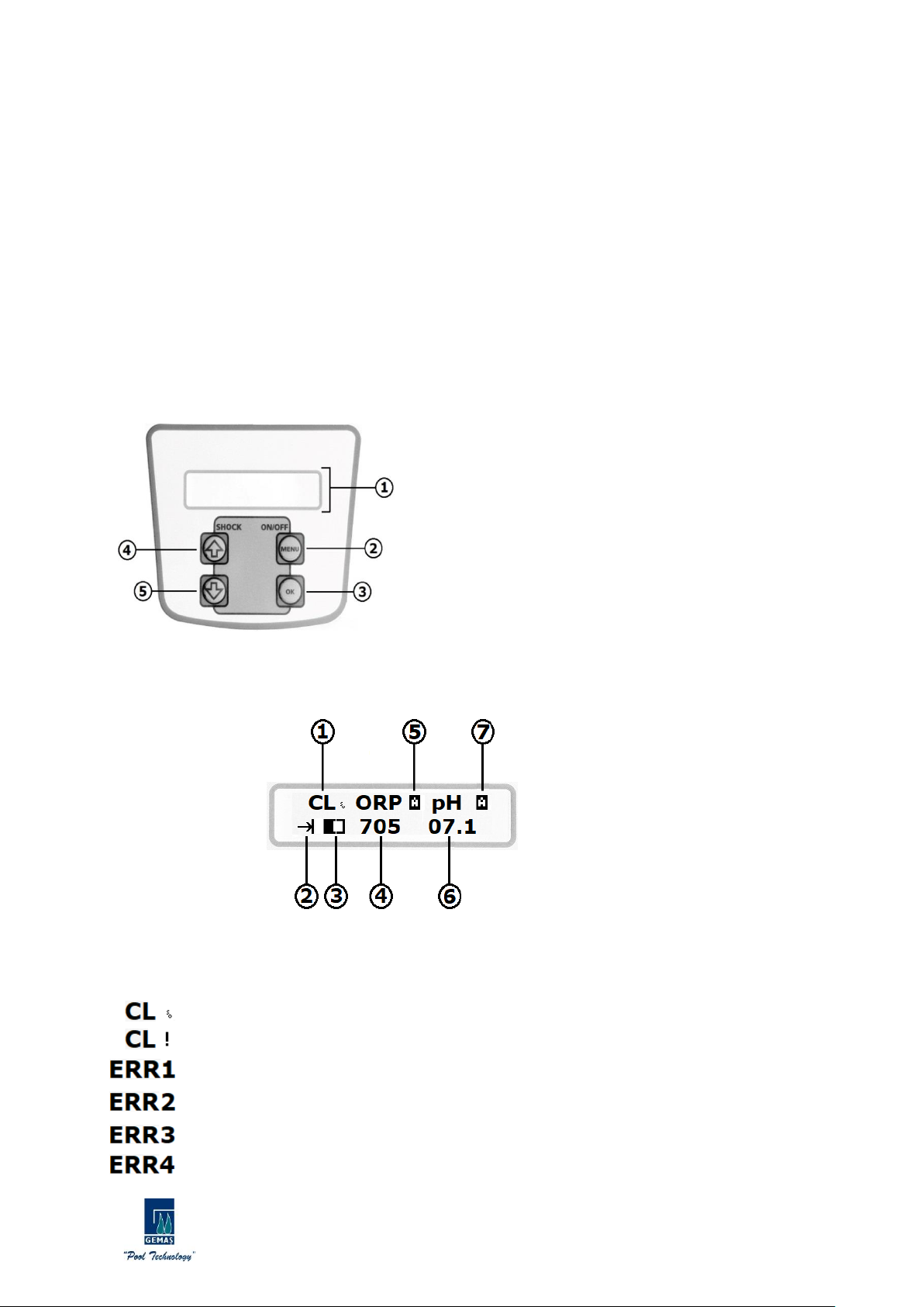
1 - 2x16 LCD screen; information and warnings about the
device are displayed.
2 - The device performs the functions of ON / OFF (switching on
/ off), entering the setting menu (the device is turned off,
pressed for 3 seconds when it is OFF), and exit the pages and
parameters in the setting menu.
3 - Selection of the pages and parameters in the setting menu,
performs the functions of confirming and saving the set
parameters.
4 - In the settings menu, it performs the functions of passing to
the next page or parameter and increasing the parameter
values.
5 - In the settings menu, it performs the functions of switching to a sub-page or parameter and decreasing
parameter values.
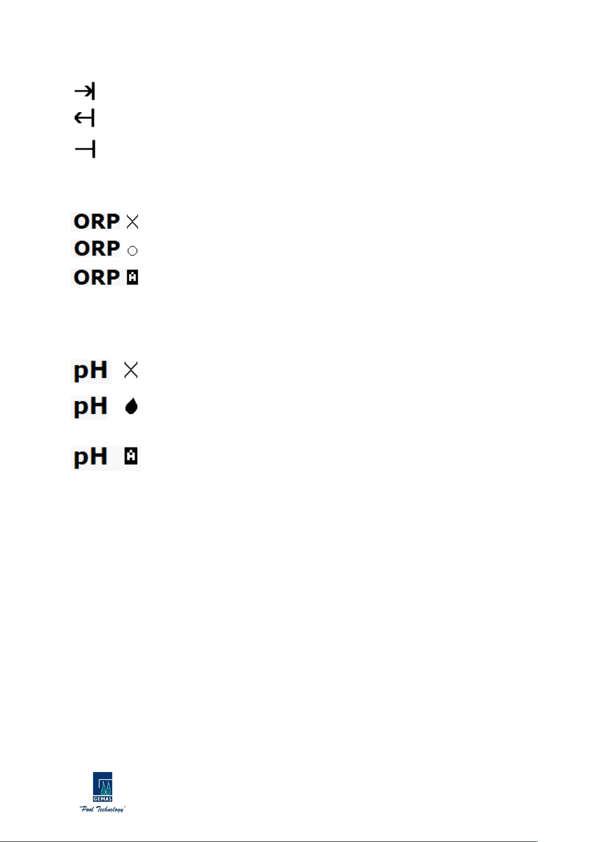
3.1.1. Control Panel Operation Screen Icons and Values
1 - Failure and Warning Part Related to Cl Production: This section shows errors and warnings affecting Cl
production. By pressing the OK button once, the instantaneous current value drawn during production is
displayed. Detailed information about faults is described in Fault Codes and Suggested Solutions.
It states that Cl is produced and the salt level is ideal.
It indicates that Cl is produced, but the level of salt is incomplete.
Indicates a malfunction with the electrode cable.
Indicates lime between the electrode plates.
Indicates a short circuit between the electrode cable or electrode plates.
This means that there is a problem with the electronic circuit board, the seller/manufacturer must
be contacted.

GEMAŞ Genel Mühendislik Mekanik San.ve Tic.A.Ş.
İTOB Organize Sanayi Bölgesi 10001 Sok.No:28 Menderes/İZMİR TURKEY
Tel:0232 799 0 333 Fax:0232 799 0 330 www.gemas.com.tr info@gemas.com.tr
10
2 –CL Production and Polarization Icon: 3 different icons appear in this section:
Right directional polarization symbol.
Reverse polarization icon. Working in reverse polarization does not harm the device. The lime removal
feature on the electrodes is activated.
No polarization. Cl is not produced. The device is out of product range or polarization changes are
made.
3 –CL production rate icon can be increased or decreased with the arrow keys.
4 –This is the part where the measured instant ORP value is shown.
Note: For devices without the ORP measurement feature, no value appears in this section.
5 –ORP Production Control Mode Icon: 3 different icons appear in this section:
ORP mode: It is OFF. Production of Cl was stopped. If it is desired to change it, it can be
changed via ORP SETTINGS> ORP MODE parameter in the Settings menu.
ORP mode: It is ON. Cl is produced continuously. If it is desired to change it, it can be
changed via ORP SETTINGS> ORP MODE parameter in the Settings menu.
ORP mode: It is AUTO. Cl is produced according to the value read in the ORP sensor and the
set value. When the desired value is found, Cl production stops automatically. If it is desired
to change it, it can be changed via ORP SETTINGS> ORP MODE parameter in the Settings menu.
6 –This is the part where the measured pH value is shown.
Note: In devices without a pH measurement feature, no value appears in this section.
7 –pH Reducer / Booster Dosing Control Mode Icon: 3 different icons appear in this section:
pH mode: It is OFF. pH lowering/booster dosing control is off. If it is desired to change it, it
can be changed in the Settings menu via the PH SETTINGS> PH MODE parameter.
pH mode: It is in the AUTO position. Reducing/increasing liquid dosing is performed in line
with the value read in the pH sensor, the set value, and the type of liquid. If it is desired to
change it, it can be changed in the Settings menu via the PH SETTINGS> PH MODE
parameter.
pH mode: It is in the AUTO position. Reducing/increasing liquid dosing will be done in line
with the value read on the pH sensor, set value, and liquid type. If it is desired to change it,
it can be changed in the Settings menu via the PH SETTINGS> PH MODE parameter.

GEMAŞ Genel Mühendislik Mekanik San.ve Tic.A.Ş.
İTOB Organize Sanayi Bölgesi 10001 Sok.No:28 Menderes/İZMİR TURKEY
Tel:0232 799 0 333 Fax:0232 799 0 330 www.gemas.com.tr info@gemas.com.tr
11
3.2. Setting Menu
The setting menu is an interface with the setting pages and
parameters of the device. It allows the device to operate at an
optimum level with the changes and adjustments made. The device is
switched off to enter the setup menu. An image like the one will
be displayed on the LCD screen. The MENU button is kept
pressed for 3 seconds while the device is in the OFF position. The
device will automatically switch to the setting menu.
Setting menu contents are shown in the table on the right. In
the table, the setting pages and the parameters in the pages are
indicated.
3.2.1. POLARITE PERIOD
Although the physical properties of the water used vary depending on geographical regions, it inevitably
contains certain amounts of calcium, magnesium, iron, and other minerals. While the water is cold, these
suspended minerals dissociate from the water during electrolysis, some of them stick to the electrodes in the
chamber. After a certain period, the electrodes are completely covered with the substance called lime. Since the
lime layer is insulating, it complicates the flow of electricity between the electrodes. As a result, chlorine
production efficiency decreases. This lime formed in the electrodes must be cleaned periodically.
This cleaning process; It has the feature to do it automatically by
changing the polarization. Polarity period page is the page where the
polarization change time is set. The OK button is pressed once to
enter the page, and to exit the page, the MENU button must be
pressed once. When entering the setting page, the parameter value is
changed with UP and DOWN direction buttons. When the desired
value is given, it is selected and saved with the OK button.
3.2.2.LANGUAGE
It is the page where the working language of the device is set.
There are English - TURKISH - FRENCH - BULGAR - GERMAN -
HUNGARY - SPANISH languages defined on the device. The OK button
is pressed once to enter the page, and to exit the page, the MENU
button must be pressed once. The working language is changed with
UP and DOWN direction buttons. When the desired working language
is displayed, the OK button is pressed once and the working language
is selected and saved.
Settings
1 - POLARITY PERIOD
POLARMA HOUR
2 - LANGUAGE
ENGLISH
TURKISH
FRENCH
BULGARIAN
GERMAN
HUNGARIAN
SPANISH
3 - PH SETTINGS
PH MOD
PH SET
PH TOL.
PH BUF. SEC
PH CALIBRATION
READ PH
PH LVL. SEC
4 - ORP SETTINGS
ORP MOD
ORP SET
ORP TOL.
ORP CALIBRATION
READ ORP
5 - PROGRAM MENU
PASSWORD

GEMAŞ Genel Mühendislik Mekanik San.ve Tic.A.Ş.
İTOB Organize Sanayi Bölgesi 10001 Sok.No:28 Menderes/İZMİR TURKEY
Tel:0232 799 0 333 Fax:0232 799 0 330 www.gemas.com.tr info@gemas.com.tr
12
3.2.3. PH SETTINGS
It is the page where pH settings are made. The OK button is
pressed once to enter the page, and to exit the page, the MENU
button must be pressed once. Direction buttons UP and DOWN are
used to switch between parameters on the page.
NOTE: Models without pH measurement feature do not have this setting page.
3.2.3a.pH Mode
It is the parameter that the dosing mode of pH decreasing or
rising liquid is set. The OK button is pressed once and the parameter
is entered, to exit, the MENU button must be pressed once. UP and
DOWN buttons are used to switch between Mod in the parameter.
There are three options in this parameter. (OFF - ON - AUTO)
pH Mode OFF: When this Mode is set, the pH portion dosing is turned
off, the dosing pump will de-energize. By pressing the OK button
once, the mode is selected and saved in the system.
pH Mode ON: When this Mode is set, the pH portion dosing pump is
continuously energized and dosing. For safety reasons, it can only be
set to ON on the parameter. Once the mode is selected by pressing
the OK button once, it is saved as AUTO in the system.
pH Mode AUTO: When this Mode is set, the dosing of the lowering or
increasing liquid is done by the value read in the pH sensor and the
set value. Dosing stops automatically when the desired value is
found.
3.2.3b.pH Set
pH set value; It is the desired pH value of the pool. Dosing is
done by comparing the value read with the sensors with the set value
entered here. Dosing pH lowering or increasing liquid ensures that
the pool is at the desired pH.
The OK button is pressed once and the parameter is entered, to
exit the parameter, the MENU button must be pressed once. After
entering the parameter, a screen like the one shown is displayed. The
value here is changed with the UP and DOWN directional buttons.
When the desired value is given, it is selected and saved with the OK
button and the parameter is automatically exited.
3.2.3c.pH Tolerance
pH tolerance; It is the shear of the adjusted pH set value. The
reason for giving this value is that dosing does not occur with the
effect of fluctuation in the measurement. Thus, a more stable system
is created.
The OK button is pressed once and the parameter is entered, to
exit the parameter, the MENU button must be pressed once. After
entering the parameter, a screen like the one shown is displayed.
The value here is changed with the UP and DOWN directional
buttons. When the desired value is given, it is selected and saved
with the OK button and the parameter is automatically exited.

GEMAŞ Genel Mühendislik Mekanik San.ve Tic.A.Ş.
İTOB Organize Sanayi Bölgesi 10001 Sok.No:28 Menderes/İZMİR TURKEY
Tel:0232 799 0 333 Fax:0232 799 0 330 www.gemas.com.tr info@gemas.com.tr
13
3.2.3d.pH Buffer Sec
pH buffer flood; It is the parameter that the liquid to be dosed is
introduced to the device whether it is a pH reducer or a pH booster.
The OK button is pressed once and the parameter is entered, to exit
the parameter, the MENU button must be pressed once. After
entering the parameter, a screen like the one shown is displayed. The
situation here is changed with the UP and DOWN directional buttons.
When the desired state is given, it is selected and saved with the OK
button and the parameter is automatically exited.
3.2.3e.pH Calibration
Measurement values change over time due to the characteristic
structure of pH sensors. The change in the sensor measurement
value affects the value displayed by the device. For this reason, the
sensors must be calibrated periodically with liquids with a known pH
value (ph4-pH7). The pH Calibration parameter is used to perform
this operation.
The OK button is pressed once and the parameter is entered, to
exit the parameter, the MENU button must be pressed once. After
entering the parameter, a screen like the one shown is displayed.
The pH sensor is first immersed in the pH4 liquid and the sensor is
left in the liquid until the timer on the screen is reset.
When the timer is reset, the pH sensor needs to be immersed in
ph7 liquid and a message appears on the screen. The sensor is
removed from the pH4 liquid and dried, immersed in the pH7 liquid
and pressed the OK button once. The sensor is left in the liquid until
the timer on the screen is reset. When the timer is reset, the pH
sensor is calibrated.
3.2.3f. pH Read
pH read parameter; It is the parameter that shows the
instantaneous value that the pH sensor reads. The OK button is
pressed once and the parameter is entered, to exit the parameter,
the MENU button must be pressed once.
After entering the parameter, a screen like the one shown is
displayed. No action is taken, only the reading the sensor displays
instantly.
3.2.3g.pH Lvl. Sel.
pH lvl sec parameter; It is the parameter where the optional
sensor connected to the pH reducer or booster liquid tank to be
dosed is introduced. The OK button is pressed once and the
parameter is entered, to exit the parameter, the MENU button must
be pressed once.
PH LVL. SEL. OFF: It must be selected when there is no sensor
connected to the liquid tank to be dosed.
PH LVL. SEL. ON: If there is a sensor connected to the liquid tank
to be dosed, it must be selected. Thanks to the connected sensor;
the device gives a warning when the liquid in the tank is drained or
drops below the specified level. In this case, the device stops the
dosing pump and prevents the pump from working and being
damaged without liquid.

GEMAŞ Genel Mühendislik Mekanik San.ve Tic.A.Ş.
İTOB Organize Sanayi Bölgesi 10001 Sok.No:28 Menderes/İZMİR TURKEY
Tel:0232 799 0 333 Fax:0232 799 0 330 www.gemas.com.tr info@gemas.com.tr
14
3.2.4.ORP SETTINGS
It is the page where ORP (RX) settings are made. The OK button
is pressed once to enter the page, and to exit the page, the MENU
button must be pressed once. UP and DOWN buttons are used to
switch between parameters on the page.
NOTE: Models without ORP (RX) measurement feature do not have this setting page.
3.2.4a.ORP Mode
It is the parameter that the dosing mode of the ORP booster
liquid is set. The OK button is pressed once and the parameter is
entered, to exit, the MENU button must be pressed once. UP and
DOWN buttons are used to switch between Mod in the parameter.
There are three options in this parameter. (OFF - ON - AUTO)
ORP Mode OFF: When this Mode is set, Cl generation is turned off.
By pressing the OK button once, the mode is selected and saved in
the system.
ORP Mode ON: When this Mode is set, Cl generation is always on. By
pressing the OK button once, the mode is selected and saved in the
system.
ORP Mode AUTO: When this Mode is set, Cl is produced according to
the value read in the ORP sensor and the set value. When the desired
value is found, Cl production stops automatically.
3.2.4b.ORP Set
ORP set value; The ORP (RX) value that the pool must have.
Dosing is done by comparing the value read with the sensors with the
set value entered here. The dosed liquid ensures that the pool is at
the desired ORP (RX) value.
The OK button is pressed once and the parameter is entered, to
exit the parameter, the MENU button must be pressed once. After
entering the parameter, a screen like the one shown is displayed. The
value here is changed with the UP and DOWN directional buttons.
When the desired value is given, it is selected and saved with the OK
button and the parameter is automatically exited.
3.2.4c.ORP Tolerance
ORP (RX) tolerance; It is the slip share from the set ORP (RX) set
value. The reason for giving this value is that dosing does not occur
with the effect of fluctuation in the measurement. Thus, a more
stable system is created.
The OK button is pressed once and the parameter is entered, to
exit the parameter, the MENU button must be pressed once. After
entering the parameter, a screen like the one shown is displayed. The
value here is changed with the UP and DOWN directional buttons.
When the desired value is given, it is selected and saved with the OK
button and the parameter is automatically exited.

GEMAŞ Genel Mühendislik Mekanik San.ve Tic.A.Ş.
İTOB Organize Sanayi Bölgesi 10001 Sok.No:28 Menderes/İZMİR TURKEY
Tel:0232 799 0 333 Fax:0232 799 0 330 www.gemas.com.tr info@gemas.com.tr
15
3.2.4d.ORP Calibration
Due to the characteristic structure of ORP (RX) sensors, the
measurement values change over time. The change in the sensor
measurement value affects the value displayed by the device. For
this reason, sensors must be calibrated periodically with fluids with
an ORP (RX) value known (475mV). ORP Calibration parameter is
used to perform this operation.
The OK button is pressed once and the parameter is entered,
to exit the parameter, the MENU button must be pressed once.
After entering the parameter, a screen like the one shown is
displayed. The ORP (RX) sensor is immersed in 475mV liquid and
the sensor is left in the liquid until the timer on the screen is reset.
When the timer is reset, the ORP (RX) sensor is calibrated.
3.2.4e.ORP Read
Read ORP parameter; It is the parameter that shows the
instantaneous value that the ORP sensor reads. The OK button is
pressed once and the parameter is entered, to exit the parameter,
the MENU button must be pressed once. After entering the
parameter, a screen like the one shown is displayed. No action is
taken, only the reading the sensor displays instantly.
3.2.5.PROGRAM MENU
It is the setting page where GEMAŞ technical personnel can intervene. Modifying this page may damage
the overall operation of the device.
4 –CLEANING - MAINTENANCE INSTRUCTIONS
4.1. Electrode Cleaning
Although the physical properties of the water used vary depending on geographical regions, it inevitably
contains certain amounts of calcium, magnesium, iron, and other minerals. While the water is cold, these
suspended minerals decompose from water during electrolysis, some of them stick to the electrodes in the
chamber. After a certain period, the electrodes are completely covered with the substance called lime. Since the
lime layer is insulating, they complicate the flow of electricity between the electrodes. As a result, chlorine
production efficiency decreases. This lime formed in the electrodes must be cleaned periodically.
This cleaning process; It has the feature to do it automatically by changing the polarization. However, in
cases where the calcium concentration is too high, this feature may not completely remove the limescale.
Regularly check the lime sediment in the cell and, if necessary, clean the cell manually.
1- Turn off the pump and salt chlorine generator.
2- Close the water inlet and water outlet valves of the electrode cell.
3- Open the threaded electrode head, properly disconnect the electrode cable from the terminal and
remove the electrode from the chamber.
4- Ideally, if the electrode is expected to dry for a day, the lime residue releases itself. During the
process, be careful not to damage the sensitive cover of the electrode and take care. During this
process, never hit with metal material that can scratch the electrode. Pressurized water can be used to
dissolve limescale.
5- If the pressurized water could not remove the limescale, you can immerse the electrode in a 20%
hydrochloric acid solution. The terminals at the top of the electrode must not touch the solution.
6- Immediately after cleaning, the electrode must be rinsed with clean water, the place of the terminals
must be carefully dried and reassembled.
Never leave the electrode in acid for more than 5 minutes! Do not scratch the electrode with metal
objects! For safety reasons, keep the acid in water! Never leave the electrode in acid for more than
5 minutes! Do not scratch the electrode with metal objects! Soak the acid in water for safety
reasons!

GEMAŞ Genel Mühendislik Mekanik San.ve Tic.A.Ş.
İTOB Organize Sanayi Bölgesi 10001 Sok.No:28 Menderes/İZMİR TURKEY
Tel:0232 799 0 333 Fax:0232 799 0 330 www.gemas.com.tr info@gemas.com.tr
16
4.2. Advices
The bipolar cells of the GSC salt chlorine generator are manufactured using a special technique, providing an
extraordinary period and resistance below the high-quality standards. However, some factors prevent you from
getting the full and longest performance from the electrode. These:
•Run with lime residue on the surface of the electrode
•Excessive chlorine concentration (over 3.00 ppm chlorine is corrosive.)
•Working with high or low pH
•Working with salt-free or high concentration salt
•Operating in water below 10 ° C
•Adding salt while the chlorinator is running
•Injecting pH regulator without placing skimmer or bottom strainer
It is recommended to periodically check the cell terminals and lubricate against sulfurization. Situations where
you need to turn off the equipment:
•Working without water
•While cleaning the filter
•When emptying the pool
•When the water freezes
•While cleaning the cell
4.3 - Fault Codes and Suggested Solutions
Fault Code
Possible Failure
Solution Way
ERR1
Cable is broken or not touching
Check cable and connection
terminals, replace if
necessary.
Electrode wiring problem
Check electrode cable
connection terminals.
Heavy lime
Clean the lime from the cell
and reduce the polarity
period.
ERR2
There is lime
Clean the lime from the cell
and reduce the polarity
period.
The water is too hard
Soften the water.
ERR3
Device output has a short
circuit
Check device electrode cable,
electrode connection
terminals, and replace it if
necessary.
ERR4
Electronic card failure
Contact the manufacturer.
5 –WARRANTY - AFTER-SALES SERVICE - SPARE PARTS
1. The electronic cell and rectifier are under a two-year warranty.
2. The products are taken out of the scope of warranty by the following items.
a. Malfunctions caused by using the product contrary to the operating instructions.
b. Malfunctions due to incorrect electrical connections.
c. Faults caused by crash and similar accidents.
d. Malfunctions that will arise from water in its rectifier.
to. Faults resulting from operation without a bypass circuit (according to the wiring diagram).
f. Malfunctions caused by acid spillage into the skimmer without turning off the rectifier.
g. Malfunctions caused by insufficient air circulation in the engine room where the acid tank used for
disinfection is located.
h. The Puritron; It must not be in the same environment with cleaning equipment, including pumps,
filters, and multi-way valves.

GEMAŞ Genel Mühendislik Mekanik San.ve Tic.A.Ş.
İTOB Organize Sanayi Bölgesi 10001 Sok.No:28 Menderes/İZMİR TURKEY
Tel:0232 799 0 333 Fax:0232 799 0 330 www.gemas.com.tr info@gemas.com.tr
17
TR GEMAŞ PURITRON KULLANMA TALİMATI V1.5
Ön Bilgi
“Gemaş markalı ürünlere gösterdiğiniz güven ve desteğiniz için teşekkürler. “
GEMAŞ Tuz Klor Jeneratörü; küçük ve orta ölçekli ev havuzlarında tuz elektrolizi işlemini
gerçekleştirmek amacıyla tasarlanmış ve üretilmiştir.
Kullanma talimatı montaj yapılmadan önce dikkatli bir şekilde okunmalı ve
montaj işlemi tecrübeli teknisyenler tarafından yapılmalıdır. Montaj
talimatına aykırı şekilde montajlanan; elektrik ve su bağlantıları yapılan
ürünlerde oluşabilecek hasar ve arızalar garanti kapsamı dışındadır.
GEMAŞ Tuz Klor Jeneratörü sadece küçük ve orta ölçekli havuzlarda tuz
elektrolizi işlemi için tasarlanmış ve üretilmiş bir cihazdır. Satın aldığınız cihazı başka
amaçlar için kullanmak; gerek cihaz için, gerekse kullanılan mahal ve kullanan kişiler için
tehlike arz edebilir.
Topraklama bağlantısını düzgün bir topraklama hattına bağlayınız. Elektrik
enerjisini kaçak akım koruması bulunan bir hattan alınız.
DİKKAT! Elektrik çarpması sonucu ciddi yaralanmalar hatta ölümler meydana
gelebilir. Bu yüzden tecrübeli teknisyenlerden yardım isteyiniz.
Can güvenliği ve ürün açısından; çocukların ulaşamayacağı yerlere montajı
yapılmalıdır.
Montaj ve devreye alma işlemleri kesinlikle yetkili servis veya ehliyetli
elektrikçi ve tesisatçı tarafından gerçekleştirilmelidir. Aksi halde hatalı
montaj ve devreye almadan kaynaklanabilecek sorunlardan üretici ve satıcı
firma sorumlu tutulamaz. Garanti kapsamında tamir, bakım ve parça değişimi
talep edilemez.

GEMAŞ Genel Mühendislik Mekanik San.ve Tic.A.Ş.
İTOB Organize Sanayi Bölgesi 10001 Sok.No:28 Menderes/İZMİR TURKEY
Tel:0232 799 0 333 Fax:0232 799 0 330 www.gemas.com.tr info@gemas.com.tr
18
Tuz Elektrolizi ve Avantajları
Tuz elektrolizi; arıtılacak suyun içerisinde bulunan tuzun elektrolitik işlemle, kuvvetli bir
oksidasyon ajanı olan serbest klora dönüştürülmesini sağlayan su arıtma metoduna verilen isimdir.
Bu teknikle; suların temiz ve hijyenik kalmasını sağlayan kimyasalların önemli bir kısmının
kullanımına gerek kalmamakta, bu kullanımdan kaynaklanabilecek kaza ve kontrol riskleri de
ortadan kalkmaktadır. Rutubetli ve sıcak makina dairelerinde; ağır gaz çıkartan klor ve asitlerin
birbirine karıştırılmasından doğabilecek ölümcül kaza riskleri bu sistemle ortadan kalkmaktadır.
Satın alınan hipo çözeltilerinin yaz koşullarında depolama süresinin kısalığı, sıcaktan kaynaklı
konsantrasyon kaybı; sistemin cazibesini önemli ölçüde arttırmaktadır.
Bunlara ek olarak, proseste klorun yanı sıra üretilen oksijen radikallerinin yüksek oksidasyon
etkisi ile son derece ışıltılı ve berrak bir su kalitesi sağlanabilmektedir. Sistem; havuzun filtrasyon
sistemi ile birlikte senkrone çalışmakta ve dezenfeksiyonu sürekli kılmaktadır. Sistemin uygulamada
getirdiği kolaylık, en az sağladığı üstün su kalitesi ve hijyeni kadar yüksektir.
Prosesle elde edilen ışıltılı ve hijyenik havuz suyu, sağlanan kullanım kolaylığı,
kimyasal kullanım masraflarında büyük tasarruf ve emniyet; sistemi vazgeçilmez kılan
temel özellikleridir.

GEMAŞ Genel Mühendislik Mekanik San.ve Tic.A.Ş.
İTOB Organize Sanayi Bölgesi 10001 Sok.No:28 Menderes/İZMİR TURKEY
Tel:0232 799 0 333 Fax:0232 799 0 330 www.gemas.com.tr info@gemas.com.tr
19
1 –ÜRÜN ÖZELLİKLERİ
•Gözyaşındaki tuzluluk ile aynı oranda tuz konsantrasyonundaki suda klor üretir.
•LCD ekran ile kullanım kolaylığı sağlayan kullanıcı dostu bir ara yüze sahiptir.
•Kireçlenmeye karşı otomatik elektrot temizleme özelliği bulunur.
•0 –14pH arası ölçüm ve kontrol özelliği sayesinde havuz sürekli istenilen pH değerinde
kalır.
•0 –1000mV arası ORP ölçümü sayesinde havuzun klor ihtiyacı kadar üretim yapmasını
sağlar.
•Uzun ömürlü titanyum elektroda sahiptir.
•16.000 saat elektrot ömrü bulunur.
•Elektrotların temizlenmesi için kutup değişim süresi artırıp azaltılarak optimum seviyeye
ayarlama imkanı sunar.
•LCD ekran sayesinde, çalışma anındaki akımı görüntüleme imkanı sağlar.
•Cihaz toplam çalışma süresini kaydeder.
•Mevcut havuza kolaylıkla uygulanabilir.
•Önerilen minimum tuzluluk 4000ppm’dir(4kg/m3).
•Cihaz 35000ppm olan deniz suyunda da kullanılabilir özelliğe sahiptir.
1.1.Teknik Özellikler
GSC102
GSC202
GSC302
Klor Üretimi
10gr/saat
20gr/saat
30gr/saat
pH Ölçüm-Kontrol
0-14 pH
0-14 pH
0-14 pH
ORP Ölçüm-Kontrol
0-1000mV
0-1000mV
0-1000mV
Besleme Voltajı
220V AC
220V AC
220V AC
Elektrot Akımı
Max. 2A
Max. 4A
Max. 6A
Elektrot Voltajı
Max. 24V
Max. 24V
Max. 24V
Güç Tüketimi
50W
100W
150W
Max. Havuz
Ölçüleri
Ilıman
50m³
100m³
170m³
Tropikal
35m³
65m³
110m³
Maksimum Debi
450 l/dk
450 l/dk
450 l/dk
Maksimum Basınç
320 Kpa
320 Kpa
320 Kpa
Basınç Kaybı
5 Kpa
5 Kpa
5 Kpa
Hücre Tipi
Bipolar
Bipolar
Bipolar
Tuz Derişimi
4-35gr/l ppm
4-35gr/l ppm
4-35gr/l ppm
Hücre Malzemesi
PMMA
PMMA
PMMA
Elektrot Malzemesi
Titanyum
Titanyum
Titanyum
Cihaz Ölçüleri
24X32X13cm
24X32X13cm
24X32X13cm
Cihaz Ağırlığı
2.4Kg
2.4Kg
2.4Kg
Pano Ölçüleri
78X56X19cm
78X56X19cm
78X56X19cm
Kutu Ölçüleri
81X60X24cm
81X60X24cm
81X60X24cm
Kutu Ağırlığı
11,5Kg
11,5Kg
11,5Kg

GEMAŞ Genel Mühendislik Mekanik San.ve Tic.A.Ş.
İTOB Organize Sanayi Bölgesi 10001 Sok.No:28 Menderes/İZMİR TURKEY
Tel:0232 799 0 333 Fax:0232 799 0 330 www.gemas.com.tr info@gemas.com.tr
20
2 –MONTAJ –KURULUM
Montaj ve kurulum işlemleri kesinlikle yetkili servis veya ehliyetli elektrikçi ve tesisatçı
tarafından gerçekleştirilmelidir. Aksi halde hatalı montaj ve devreye almadan
kaynaklanabilecek sorunlardan üretici ve satıcı firma sorumlu tutulamaz. Garanti
kapsamında tamir, bakım ve parça değişimi talep edilemez.
Cihazın sorunsuz çalışabilmesi, can ve mal güvenliğiniz için montaja başlamadan önce elektrik
ve su ile ilgili emniyet önlemlerini alarak aşağıdaki koşulların sağlandığından emin olun.
Tesisat Şeması
Elektrik ile İlgili Açıklama
Tuz Klor Jeneratöründe can ve mal güvenliğini korumaya yönelik olarak elektriksel ve
mekanik önlemler alınmıştır. Elektriksel önlemlerin işlevini yerine getirebilmesi için
mutlaka kaçak akım rölesi ve topraklama ile ilgili uyarıların dikkate alınması
gerekmektedir.
•Kaçak Akım Rölesi: CE belgeli ve çalıştığından emin olduğunuz bir kaçak akım rölesi kullanın.
Kullanacağınız rölenin jeneratörü kontrol ettiğinden emin olun. Kesinlikle her yıl Kaçak Akım Rölesini test
edin.
Kaçak Akım Rölesinin takılmamasından, sonradan arızalanmasından, iptal edilmesinden,
topraklama kablosunun bağlanmamasından, topraklamanın zayıf olmasından
kaynaklanabilecek her türlü sorunlardan üretici/satıcı firma sorumlu tutulamaz.
•Besleme Kablosu: Cihaz besleme kablosu en az 3x1,5mm olmalıdır.
•Topraklama: Tesisinizdeki topraklamanın iyi yapılmış olduğundan emin olun. Tesisatın topraklama hattını
mutlaka cihaza bağlayın. Gerekirse topraklama hattını test edin. Faz ile nötr arasında gördüğünüz voltaj
değerini faz/toprak arasında da görmeniz gerekmektedir. Nötr ve toprak arası voltaj değeri en çok 2 V AC
olmalıdır.
L-N: 220V AC L-PE: 220V AC N-PE: Maksimum 2V AC
This manual suits for next models
2
Table of contents
Languages:
Other Gemas Lighting Equipment manuals