www.tinytag.info
www.tinytag.infowww.tinytag.info
www.tinytag.info
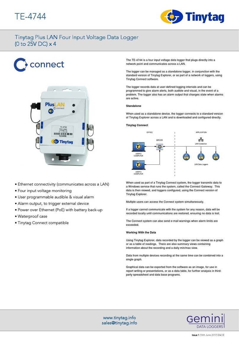
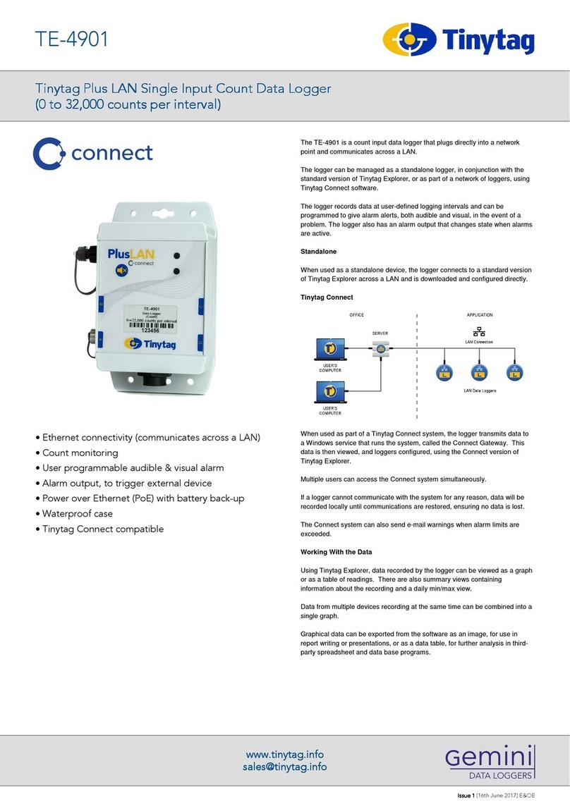
Tinytag Plus LAN Four Input Voltage Data Logger
Tinytag Plus LAN Four Input Voltage Data Logger Tinytag Plus LAN Four Input Voltage Data Logger
Tinytag Plus LAN Four Input Voltage Data Logger
(0 to 2.5V D ) x 4
(0 to 2.5V D ) x 4(0 to 2.5V D ) x 4
(0 to 2.5V D ) x 4
TE-4743
Issue 1
Issue 1 Issue 1
Issue 1 (16th June 2017) E&OE
Required Parts
Two Ethernet cables (not supplied) are required to connect this receiver
to a LAN.
This logger is a PoE device and is supplied with a PoE injector as standard. If
the logger is being used on a powered network, or a number of loggers are
being connected to a powered hub, this product can be supplied without the
injector.
When used as a standalone device, a copy of the following software is
required:
SWCD-0040 Tinytag Explorer
When used as part of a Tinytag Connect system, a copy of the following
software is required:
SWCD-0080 Tinytag Explorer Connect
Connections
You will also require four of either of the following:
CAB-3239 Tinytag Voltage Input Leads (supplied) or
ACS-9703 5-Pin Plugs
Further Related Products
ACS-0040 RJ45 waterproof (IP67) Shroud (supplied)
ACS-0041 PoE Injector (supplied)
CAB-0041 Plus LAN alarm output lead
Required and Related Products
Power Information
This logger is a PoE (Power over Ethernet) device that is powered from its
Ethernet connection (a PoE injector is supplied).
In the event of a failure of the PoE supply, the logger has a battery back-up
that will keep it recording (communications will be suspended until power is
restored).
Back-up Battery Power
Battery Type 2 x Duracell Industrial ID1500
AA (LR6) 1.5V (supplied)
The logger will operate with other AA cell batteries but performance cannot be
guaranteed.
When the logger’s back-up batteries start to run flat, the LED on the front of
the logger will flash red. If being used as part of a Tinytag Connect system, a
low battery warning will be displayed in the Tinytag Explorer Connect software.
The low battery warnings will start to show when the logger has approximately
two weeks of battery power remaining.
Before replacing batteries the logger must be disconnected from the LAN and
turned off.
Alkaline batteries should always be replaced in pairs.
Data stored in the logger will be retained after its batteries are replaced.
Warranty
This logger is configured to meet Gemini’s quoted accuracy specification
during its manufacture.
We recommend that the calibration of this unit should be checked annually
against a calibrated reference meter.
A traceable certificate of calibration can be supplied for an additional charge
either at the point of purchase, or if the unit is returned for a Service
Calibration.
Calibration
This product carries a manufacturing defects warranty of 12 months from the
date of purchase. Units returned under warranty will be repaired or replaced at
the manufacturer’s discretion. This warranty does not cover mishandling,
modification or battery replacement and is subject to our standard Terms and
Conditions of Sale, a copy of which can be found at www.tinytag.info.
Action LED Status/Operation
n/a No Indicators Device is powered off
n/a Red flash every 4
seconds
The device is powered on and
has a problem.
Either:
a) Battery is low or
b) An alarm indicator is
signalled.
Check the nature of the
problem using Tinytag
Explorer.
n/a Green flash every 4
seconds
The device is powered on, and
does not have any problems.
Press and briefly
hold the mute
switch.
Green indicator
shows for one
second. It then
briefly flashes green
then red.
The device has been switched
on.
Press and hold the
mute switch for 3
seconds.
Red indicator shows
for one second.
The device has been switched
off.
n/a Yellow indicator on
constantly
The device is being powered
from its Ethernet connection,
but no communications have
been established.
n/a Blue (flickering) Ethernet communications are
established and on-going
Ethernet Radio Receivers and LAN data loggers have two status LEDs; one to
show the status of the logger’s Ethernet connection (yellow/blue) and the
second to show the status of the unit (green/red).
Note that the yellow and blue LEDs cannot be on at the same time. If the
blue LED is on (or flickering) then PoE power must be available.
LED Flash Patterns
Approvals
Gemini Data Loggers (UK) Limited hereby declares that this data logger is in
compliance with the essential requirements and other relevant provisions of
EMC directive 2014/30/EU and RoHS directive 2011/65/EU. A copy of the
declaration of conformity is available upon request.
This logger also conforms to the following EMC standards EN 61326-1:2013,
FCC/CFR 47:Part 15:2016 & Canadian Standard ICES-003:Issue 6.
This logger also complies with (RJ45) 10/100Mb Base-T for Ethernet
connectivity and PoE standard IEEE 802.3af.
Gemini Data Loggers (UK) Ltd. operates a Business Management System
which conforms to ISO 9001 and ISO 14001.
