SENSECAP S2100 User manual

T H E N E W G E N E R A T I O N L O R A W A N S E N S O R S O F S E N S E C A P
S2100 LoRaWAN Data Logger
User Guide
Version: v1.2.1

Table of Contents
1. Product Introduction .......................................................................................4
2. Part List ............................................................................................................5
3. Quick Start ....................................................................................................... 6
3.1 Sensor Configuration Example .................................................................................. 6
4. Hook up the Sensor Probe ............................................................................. 7
4.1 Preparation ................................................................................................................. 7
4.1.1 Sensor Probe ..................................................................................................................... 7
4.1.2 Tools .................................................................................................................................. 7
4.2 Connect the Sensor Probe .........................................................................................8
4.2.1 Disassemble the Data Logger ........................................................................................... 8
4.2.2 Power supply options of sensor .........................................................................................9
4.2.3 How to install external 12V DC ........................................................................................10
5. LED of Sensor Working Status .................................................................... 14
6. SenseCAP Mate App .....................................................................................16
6.1 Download App .......................................................................................................... 16
6.2 How to connect sensor to App ................................................................................. 17
6.2.1 Create a New Account .....................................................................................................17
6.2.2 Connect to Sensor to App ................................................................................................18
6.3 Configure basic parameters through App ................................................................ 20
6.3.1 Select the Platform and Frequency ................................................................................. 20
6.3.2 Set the Interval .................................................................................................................24
6.3.3 Set the EUI and Key ........................................................................................................ 24
6.3.4 Set the Packet Policy .......................................................................................................25
6.3.5 Set the Activation Type ....................................................................................................25
6.3.6 Restore Factory Setting ................................................................................................... 26
6.4 Configure Level or Pulse Sensor via App ................................................................ 27
6.4.1 Set the Level Mode ..........................................................................................................28
6.4.2 Set the Counter Mode ......................................................................................................28
6.5 Configure Analog Sensor via App ............................................................................31
6.5.1 Set the 4~20mA sensor ................................................................................................... 31
6.5.1 Set the 0~10V Voltage sensor .........................................................................................32
6.6 Configure RS485 Modbus-RTU Sensor via App ..................................................... 34
7. Connect to the SenseCAP Portal .................................................................37
7.1 SenseCAP Portal ......................................................................................................37
7.1.1 Create a New Account .....................................................................................................37
7.1.2 Other Functions ............................................................................................................... 37
7.1.3 API Instruction ..................................................................................................................38

7.2 Connect to SenseCAP with Helium Network ........................................................... 39
7.2.1 Quick Start ....................................................................................................................... 39
7.2.2 Preparation ...................................................................................................................... 39
7.2.3 Bind Sensor to SenseCAP Portal .................................................................................... 40
7.2.4 Setup the Sensor ............................................................................................................. 42
7.2.5 Set Frequency of Sensor via SenseCAP Mate App ........................................................43
7.2.6 Check Data on SenseCAP Portal ....................................................................................44
7.3 Connect to SenseCAP with private TTN ..................................................................46
7.3.1 Quick Start ....................................................................................................................... 46
7.3.2 Preparation ...................................................................................................................... 46
7.3.3 Bind Sensor to SenseCAP Portal .................................................................................... 47
7.3.4 Setup the Sensor ............................................................................................................. 48
7.3.5 Set Frequency of Sensor via SenseCAP Mate App ........................................................48
7.3.6 Check Data on SenseCAP Portal ....................................................................................49
8. Connect to Helium Network ......................................................................... 50
9. Connect to The Things Network .................................................................. 50
10. Payload Decoder ......................................................................................... 51
10.1 Decoder Code ........................................................................................................ 51
10.2 Packet Parsing ....................................................................................................... 52
10.2.1 Packet Initialization ........................................................................................................ 52
10.3 Data Parsing Example ............................................................................................54
10.3.1 Example - one measurement ........................................................................................ 54
10.3.2 Example - two measurements ....................................................................................... 54
10.3.3 Example - four measurements ...................................................................................... 55
10.3.4 Example - six measurements ........................................................................................ 56
10.3.5 Battery Information ........................................................................................................ 57
11. LoRaWAN Downlink Command ................................................................. 59
11.1 Set the Data Uplink Interval ................................................................................... 59
11.2 Reboot the device ...................................................................................................60
11.3 How to send downlink ............................................................................................ 60
12. Device Installation .......................................................................................61
12.1 Check the waterproof performance of the device ..................................................61
12.1.1 Data logger connection port .......................................................................................... 61
12.1.2 Waterproof check ...........................................................................................................61
12.2 Installing Sensor ..................................................................................................... 61
12.2.1 Installing the Sensor Bracket .........................................................................................61
12.2.1 Mount on Pole and Wall .................................................................................................63
12.3 Replace the Battery ................................................................................................ 65
12.3.1 How to Buy the Battery .................................................................................................. 65
12.3.2 How to Replace a New Battery ......................................................................................66

13. Trouble Shooting ........................................................................................ 68
13.1 Sensors can’t join LoRa network, how to do? ........................................................68
13.2 Why is the new sensor’s battery not 100%? ..........................................................68
13.3 Support ................................................................................................................... 68
13.4 Document Version ..................................................................................................68

IoT into the Wild
4
1. Product Introduction
S2100 LoRaWAN Data Logger can collect data from different types of sensors and transfer
the data through LoRaWAN network. If you have deployed sensors that are not based on the
LoRaWAN network, then with our LoRaWAN Data Logger, you can change them into
LoRaWAN-based sensors and use the LoRaWAN network to transfer data. You can easily
enjoy the advantages of LoRaWAN technology such as low power consumption and long
transmission range, without affording the cost of changing the sensors you are using.

IoT into the Wild
5
2. Part List
Before installing, please check the part list to ensure nothing is missing.
Picture
Name
Quantity
Data Logger
1
Bracket
1
Quick Start Guide
1
KA4*20mm Self-drilling Screw
4
A junction box accessory kit is available as an additional option, and be ordered separately:
Picture
Name
Quantity
Junction box
1
8 pin wire (40cm)
1
Waterproof adhesive tape
1

IoT into the Wild
6
3. Quick Start
Refer to the following steps for quick configuration with SenseCAP server.
Step
Description
Section
1
Hook up the sensor probe
Section 4
2
Download SenseCAP Mate App
Section 6.1
3
Configure the LoRaWAN parameters
Section 6.3
4
Configure the sensor protocol
Section 6.4 for level / pulse
sensor
Section 6.5 for analog sensor
Section 6.6 for RS485 sensor
5
Join LoRaWAN network server
Section 7.2 or 7.3
6
Check the data on the SenseCAP Dashboard
and SenseCAP Mate App
Section 7.2.6
7
Deploying sensors
Section 12
3.1 Sensor Configuration Example
TBD

IoT into the Wild
7
4. Hook up the Sensor Probe
4.1 Preparation
4.1.1 Sensor Probe
Get one of these sensors ready:
Type
Sensor wire pin
RS485 Modbus-RTU
1 x A, 1 x B, 1 x GND, 1 x VCC
4~20 mA
1 or 2 x signal pin
0~10V
1 or 2 x signal pin
Level
1 x signal pin
Pulse Count
1 x signal pin
Note:
Each Data logger can only be connected to one type of sensor. For example
1. a RS485 sensor with one address
2. a 4~20mA sensor with 1or 2 measurements
3. a 0~10V (Less than 10v) sensor with 1or 2 measurements
4. a pulse or level sensor with 1 measurement
4.1.2 Tools
Type
Description
Cross screwdriver
Cross recess No.2

IoT into the Wild
8
4.2 Connect the Sensor Probe
4.2.1 Disassemble the Data Logger
1. Unscrew three screws.
2. Take down the cover.
3. Remove the thread cap and pass it through the cable of the sensor, pass it through
the bottom cover, and connect it to the wiring terminal.

IoT into the Wild
9
No.
Pin
Description
1
12V
External 12V input voltage. The Data Logger can be
powered by an external 12V DC power supply.
When using 12V power supply, the battery will serve as
backup power supply.
2
5V
5V output voltage, providing 5V voltage to the sensor.
3
3V
3V output voltage, providing 3V voltage to the sensor.
4
IO
Acquisition level or pulse input
5
V1
Analog voltage input ranges from 0 to 10V
6
V2
Analog voltage input ranges from 0 to 10V
7
A
RS485 A/+
8
B
RS485 B/-
9
I1
Analog current input ranges from 4 to 20mA
10
I2
Analog current input ranges from 4 to 20mA
11
GND
Ground
12
GND
Ground
4.2.2 Power supply options of sensor
Data Logger supports two power supply modes:
Mode
Description
Built-in Battery
When the Data Logger and sensors only powered by internal
battery. The datalogger only support 5V or 3V sensor probes.
External 12V DC
If some cases, the sensor probe needs a higher power source
which the internal battery cannot last for long time.
An external 12V power source could be the main power supply,
and the internal battery works as a backup power source when
the 12V power outage happen.
When using external 12V power supply, it is recommended that
working together with the junction box to make sure the
waterproof covered.

IoT into the Wild
10
4.2.3 How to install external 12V DC
When your sensor needs 12V power, the internal battery will not be able to feed the sensor.
Therefore, an external 12V power supply is required.
Take the SenseCAP ONE Weather Station as an example.
1) Prepare the12V DC adapter, Junction box, and 4-pin wire.
2) Wire the RS485-A, RS485-B and GND and external 12V input to the green terminal.
Definition of the cable:

IoT into the Wild
11
Wire color
The pin of Data Logger
Red
12V
Black
GND
Yellow
A
Blue
B
3) Put the device circuit board back to enclosure, and make sure the waterproof rubber is
well assembled.
4) Wire to the terminal of the junction box.

IoT into the Wild
12
5) Connect the sensor wire to the junction box.
6) Connect the 12V DC adapter to the power supply.
7) To complete the assembly.
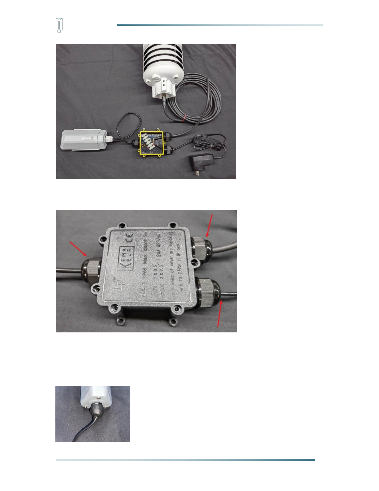
IoT into the Wild
13
8) Tighten the screws and screw caps to check the waterproofing. If the wire diameter
is too thin, add waterproof tape for winding.
*Note: When assembling the device, it is necessary to install the waterproof pad of the Data
Logger and the adapter box, and tighten the screw cap and screw, otherwise the waterproof
effect of the device may be affected!
If the wire diameter is too small, it can be wrapped with waterproof tape, as shown below:

IoT into the Wild
14
5. LED of Sensor Working Status
The LED has green and red color, which indicates the device working status explained in the
follow table:
Actions
Description
Green LED Status
First power up, press and
hold for 3s
Power on and activate the
Bluetooth
Green LED flashes at 1s
frequency, waiting for
Bluetooth connection.
If Bluetooth not connected
within 1 minute, the device
would shut down again.
Press once
Reboot device and join LoRa
network
1. The green LED will be
on for 5 seconds for
initialization.
2. Waiting for join LoRa
network: red breathing
light flashing
3. Join LoRa network
success: green LED
flashes fast for 2s
4. LoRa network join
failure: red LED
suddenly stop.
Press and hold for 3s
Activate Bluetooth again
1. Waiting for Bluetooth
connection: green LED

IoT into the Wild
15
flashes at 1s frequency
2. Enter configuration
mode after Bluetooth
connection is
successful: green LED
flashes at 2s frequency
If Bluetooth is not
connected within 1 minute,
the device will reboot and
join LoRa network.
Press and hold for 9s
Power off
In the 3rd seconds will start
flashing at 1s frequency,
until the light is steady on,
release the button, the light
will go out.
Note:
1.After power off, you need to reconfigure the frequency band. Power off is recommended
when not deployed.
2. If the frequency is not configured after power on, the device will be power off again.

IoT into the Wild
16
6. SenseCAP Mate App
6.1 Download App
As a tool, SenseCAP Mate App is used to configure LoRa parameters, set interval, bind
devices to your account and check device basic information.
(1) For iOS, please search for “SenseCAP Mate” in the App Store and download it.
(2) For Android, please search for “SenseCAP Mate” in the Google Store and download it.
You can also download App from https://install.appcenter.ms/orgs/seeed/apps/sensecap-
mate/distribution_groups/public

IoT into the Wild
17
6.2 How to connect sensor to App
6.2.1 Create a New Account
SenseCAP Mate supports device configuration and remote management. To use the
SenseCAP Portal platform and other functions, please register an account.
SenseCAP Mate supports offline functionality, and you can opt out of an account if you only
use the configuration sensor. Just click Skip.
Please select Global of Server Location.
You can also create an account via the SenseCAP Portal: http://sensecap.seeed.cc
1) Select register account, enter email information and click "register", the registered email
will be sent to the user's mailbox.
2) Open the "SenseCAP…"Email, click the jump link, fill in the relevant information, and
complete the registration.
3) Return to the login interface and complete the login.
Note:
If you can't find the email, it may be automatically identified as "spam" and put in the "trash
can".

IoT into the Wild
18
6.2.2 Connect to Sensor to App
1) Press button and hold for 3 seconds, the LED will flash at 1s frequency. Please use the
App to connect the sensor within 1 minute; otherwise, the device will power off or reboot.
2) Please select “S2100 Data Logger”.
Please click the “Setup” button to turn on Bluetooth and click “Scan”to start scanning the
sensor's Bluetooth.
3) Select the Sensor by S/N (S/N is on the front label of the sensor). Then, the basic
information of the sensor will be displayed after entering.

IoT into the Wild
19
4) Enter configuration mode after Bluetooth connection is successful: LED flashes at 2s
frequency.
Other manuals for S2100
1
Table of contents
Other SENSECAP Data Logger manuals


