GEMINI CONTROLS LLC
Phone (262) 377-8585
P.O. Box 380 W61 N14280 Taunton Ave. FAX (262) 377-4920
Cedarburg, WI 53012 Email: sales@geminicontrols.com
www.geminicontrols.com
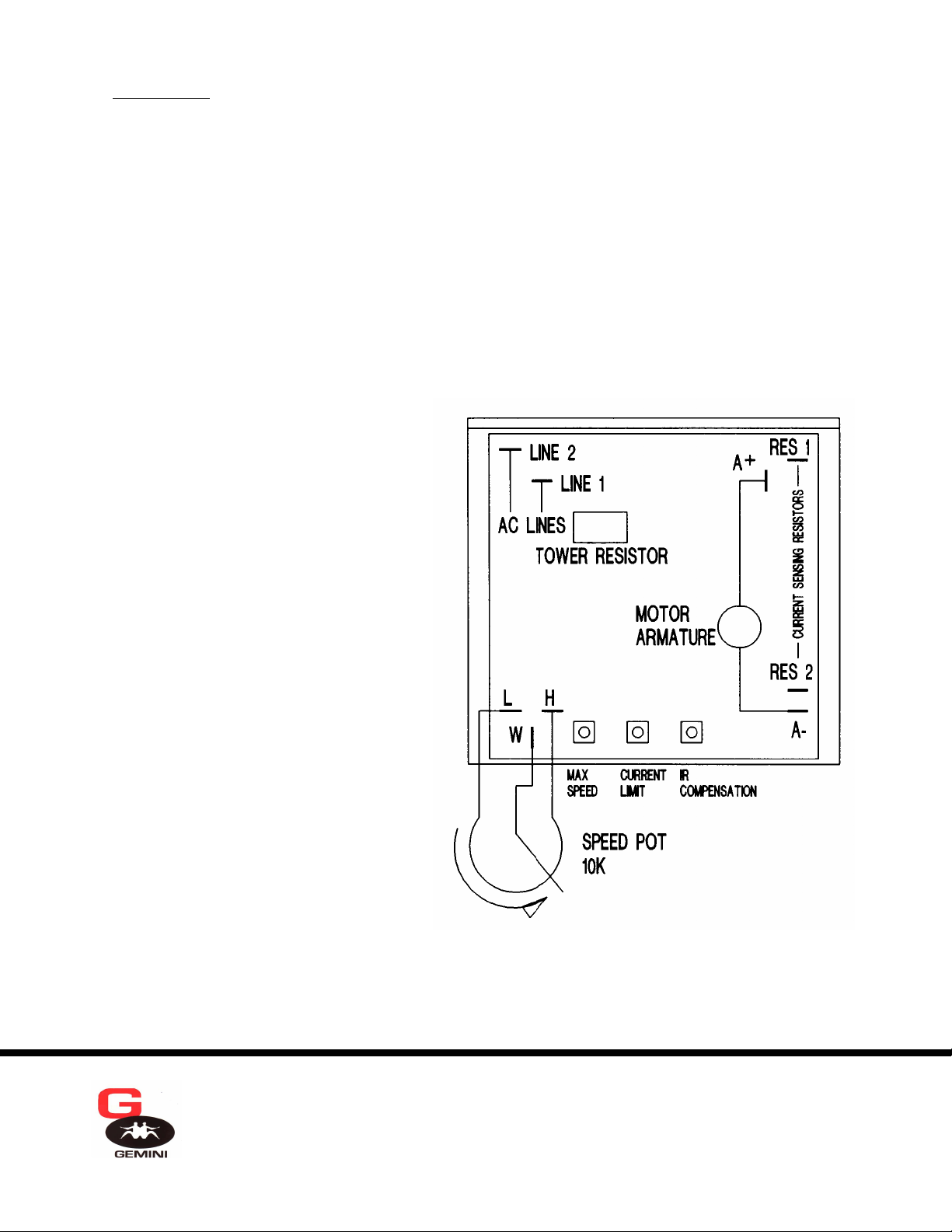
3. Control Wiring - Connect a 10K, 1/4 watt speed potentiometer to the “L”, “W”, and “H” terminals, with the wiper
connected to the “W” terminal, and the CCW end wired to the “L” terminal. If an external 0-10VDC speed reference
signal is used, first set-up and adjust the system with a 10K potentiometer as a speed reference. Connect the isolated,
external source only after satisfactory operation with a potentiometer, as any problem may then be directed toward
interfacing. The frequency of a pulse width modulated, isolated, input signal must exceed 50Hz, otherwise damage may
result. Wire the common to the “L” terminal and the positive voltage to the “W” terminal.
If shielded wire is used, ground the shield at the potentiometer. Never connect the shield at both ends. Do not run control
wiring in conduit with high voltage (115V or greater) wiring.
ADJUSTMENTS AND START-UP
1. Turn the “IRC” and “M.S.” (maximum speed) potentiometers, located on the board, and speed adjustment potentiometer
to their full counterclockwise position. Set the “C.L.” (current limit) pot. to mid-range.
2. Apply power and rotate the speed potentiometer
slightly clockwise. Observe the direction of rotation.
If incorrect, turn off the power and reverse the motor
armature connections.
3. Rotate the speed potentiometer to the extreme
clockwise position, and adjust the “M.S.”
potentiometer for the desired maximum speed, or for
rated motor voltage as measured with a DC meter at
the armature connection.
4. Adjust the “IRC” potentiometer clockwise until
the motor runs smoothly under different load
conditions. If the motor starts to surge, turn the
“IRC” pot. counterclockwise until surging stops.
Uncontrolled surging may blow the fuse or damage
the control.
5. The “CURR LIMIT” potentiometer can now be
adjusted so that the motor will not stall under
maximum load. Clockwise adjustment increases
the current limit, and the torque available from the
motor. If additional torque is required for
acceleration, increase the current limit setting.
The system is now ready for operation.


