Gemini iTRAX BLACK User manual

iPod Mixer Console
iTRAX BLACK
OPERATIONS MANUAL
MANUAL DE INSTRUCCIONES
MANUEL D’INSTRUCTIONS
BEDIENUNGSHANDBUCH
FOR ENGLISH READERS Page 2 ~ Page 5
PARA LECTORES EN ESPAÑOL Página 6~ Página 9
UTILISATEURS FRANCAIS Page 10 ~ Page 13
FÜR DEUTSCHE LESER Seite 14 ~ Seite 17
®

CAUTION: This product satisfies FCC regulations when shielded cables and connectors are used to connect the unit to other equipment. To prevent electromagnetic interfer-
ence with electric appliances such as radios and televisions, use shielded cables and connectors for connections.
The exclamation point within an equilateral triangle is intended to alert the user to the presence of important operating and maintenance (servicing) instructions in the liter-
ature accompanying the appliance.
The lightening flash with arrowhead symbol, within an equilateral triangle, is intended to alert the user to the presence of uninsulated “dangerous voltage” within the prod-
uct’s enclosure that may be of sufficient magnitude to constitute a risk of electric shock to persons.
READ INSTRUCTIONS: All the safety and operating instructions should be read before the product is operated.
RETAIN INSTRUCTIONS: The safety and operating instructions should be retained for future reference.
HEED WARNINGS: All warnings on the product and in the operating instructions should be adhered to.
FOLLOW INSTRUCTIONS: All operating and use instructions should be followed.
CLEANING: The product should be cleaned only with a polishing cloth or a soft dry cloth. Never clean with furniture wax, benzine, insecticides or other volatile liquids since
they may corrode the cabinet.
ATTACHMENTS: Do not use attachments not recommended by the product manufacturer as they may cause hazards.
WATER AND MOISTURE: Do not use this product near water, for example, near a bathtub, wash bowl, kitchen sink, or laundry tub; in a wet basement; or near a swimming
pool; and the like.
ACCESSORIES: Do not place this product on an unstable cart, stand, tripod, bracket, or table. The product may fall, causing serious injury to a child or adult, and serious dam-
age to the product. Use only with a cart, stand, tripod, bracket, or table recommended by the manufacturer, or sold with the product. Any mounting of the product should fol-
low the manufacturer’s instructions, and should use a mounting accessory recommended by the manufacturer.
CART: A product and cart combination should be moved with care. Quick stops, excessive force, and uneven surfaces may cause the product and cart combination to over-
turn. See Figure A.
VENTILATION: Slots and openings in the cabinet are provided for ventilation and to ensure reliable operation of the product and to protect it from overheating, and these open-
ings must not be blocked or covered. The openings should never be blocked by placing the product on a bed, sofa, rug, or other similar surface. This product should not be
placed in a built-in installation such as a bookcase or rack unless proper ventilation is provided or the manufacturer’s instructions have been adhered to.
POWER SOURCES: This product should be operated only from the type of power source indicated on the marking label. If you are not sure of the type of power supply to your
home, consult your product dealer or local power company.
LOCATION: The appliance should be installed in a stable location.
NON-USE PERIODS: The power cord of the appliance should be unplugged from the outlet when left unused for a long period of time.
GROUNDING OR POLARIZATION:
• If this product is equipped with a polarized alternating current line plug (a plug having one blade wider than the other), it will fit into the out-
let only one way. This is a safety feature. If you are unable to insert the plug fully into the outlet, try reversing the plug. If the plug should still
fail to fit, contact your electrician to replace your obsolete outlet. Do not defeat the safety purpose of the polarized plug.
• If this product is equipped with a three-wire grounding type plug, a plug having a third (grounding) pin, it will only fit into a grounding type
power outlet. This is a safety feature. If you are unable to insert the plug into the outlet, contact your electrician to replace your obsolete out-
let. Do not defeat the safety purpose of the grounding type plug.
POWER-CORD PROTECTION: Power-supply cords should be routed so that they are not likely to be walked on or pinched by items placed upon or against them, paying par-
ticular attention to cords at plugs, convenience receptacles, and the point where they exit from the product.
OUTDOOR ANTENNA GROUNDING: If an outside antenna or cable system is connected to the product, be sure the antenna or cable system is grounded so as to provide
some protection against voltage surges and built-up static charges. Article 810 of the National Electrical Code, ANSI/NFPA 70, provides information with regard to proper
grounding of the mast and supporting structure, grounding of the lead-in wire to an antenna discharge unit, size of grounding conductors, location of antenna-discharge unit,
connection to grounding electrodes, and requirements for the grounding electrode. See Figure B.
LIGHTNING: For added protection for this product during a lightening storm, or when it is left unattended and unused for long periods of time, unplug it from the wall outlet and
disconnect the antenna or cable system. This will prevent damage to the product due to lightening and power-line surges.
POWER LINES: An outside antenna system should not be located in the vicinity of overhead power lines or other electric light or power circuits,
or where it can fall into such power lines or circuits. When installing an outside antenna system, extreme care should be taken to keep from
touching such power lines or circuits as contact with them might be fatal.
OVERLOADING: Do not overload wall outlets, extension cords, or integral convenience receptacles as this can result in a risk of fire or electric
shock.
OBJECT AND LIQUID ENTRY: Never push objects of any kind into this product through openings as they may touch dangerous voltage points
or short-out parts that could result in a fire or electric shock. Never spill liquid of any kind on the product.
SERVICING: Do not attempt to service this product yourself as opening or removing covers may expose you to dangerous voltage or other haz-
ards. Refer all servicing to qualified service personnel.
DAMAGE REQUIRING SERVICE: Unplug this product from the wall outlet and refer servicing to qualified service personnel under the following conditions:
• When the power-supply cord or plug is damaged.
• If liquid has been spilled, or objects have fallen into the product.
• If the product has been exposed to rain or water.
• If the product does not operate normally by following the operating instructions. Adjust only those controls that are covered by the operating instructions as an improper
adjustment of other controls may result in damage and will often require extensive work by a qualified technician to restore the product to its normal operation.
• If the product has been dropped or damaged in any way.
• When the product exhibits a distinct change in performance, this indicates a need for service.
REPLACEMENT PARTS: When replacement parts are required, be sure the service technician has used replacement parts specified by the manufacturer or have the same
characteristics as the original part. Unauthorized substitutions may result in fire, electric shock, or other hazards.
SAFETY CHECK: Upon completion of any service or repairs to this product, ask the service technician to perform safety checks to determine that the product is in proper op-
erating condition.
WALL OR CEILING MOUNTING: The product should not be mounted to a wall or ceiling.
HEAT: The product should be situated away from heat sources such as radiators, heat registers, stoves, or other products (including amplifiers) that produce heat.
PLEASE READ BEFORE USING APPLIANCE
IMPORTANT WARNING AND SAFETY INSTRUCTIONS!
CAUTION RISK OF ELECTRIC
SHOCK DO NOT
OPEN!
Fig. A
Fig. B
2

iTrax Black
TOP
1
3
2
346
7
8
10
12
13
15 16
17
18
19 20 22
11
23
9
21
BACK
FRONT
6
5
14

INTRODUCTION:
4
FEATURES:
PRECAUTIONS:
CONNECTIONS:
1
6
7
CONTROLS:
8
10
11
12
Congratulations on your purchase of a iTRAX iPod© MIXER
CONSOLE. The iTRAX, aside from being stylish and easy-to-use,
is a high quality DJ mixer that can be used in a variety of settings.
With proper care and maintenance, your mixer will provide years of
reliable performance.
- Dual docking stations for Apple® iPod® digital music players
- USB port with dock switch allows library management via PC
- 2 Phono/Line convertible inputs for use with additional devices
- Composite video output for use with photo/video-enabled iPod®
- 3-Band rotary EQ with gain and cut feature per channel
- ¼" (6.35mm) Mic input with 2-Band EQ controls
- Master and Record RCA outputs
- Input selection switches
- Cue section with CH1/CH2 cue fader
- User replaceable X-Fader
- Lightweight, slimline design for complete portability
1. All instructions should be read before using this equipment.
2. To reduce the risk of electrical shock, do not open the unit.
Please refer all servicing needs to a Gemini-qualified service
technician.
3. Do not expose this unit to direct sunlight or a heat source such
as a radiator or stove.
4. This unit should be cleaned only with a damp cloth. Avoid sol-
vents or other cleaning detergents.
5. When moving this equipment it should be placed in its original
carton and packaging. This will reduce the risk of damage during
transit.
6. DO NOT EXPOSE THIS UNIT TO RAIN OR MOISTURE.
7. DO NOT USE SPRAY CLEANERS OR LUBRICANTS ON
CONTROLS, SURFACES OR SWITCHES.
AC INLET : The AC INLET, located on the rear of the unit, is the
connector which accepts the AC ADAPTER (supplied) used to
power the unit.
POWER SWITCH: The POWER SWITCH turns the unit ON or OFF.
Make sure the switch is in the ‘OFF’ position prior to making any
connections.
RCA MASTER OUTPUTS: These audio outputs carry unbalanced
audio signals from the Master bus of the mixer. The MASTER
VOLUME CONTROL determines the level of audio which is sent to
these outputs.
RECORD RCA OUTPUTS: These outputs is best suited for
connecting a recording device, as it is not altered by the MASTER
VOLUME CONTROL. This is useful in a live setting when you are
required to change the overall volume of your output, but you do not
want to change the level of audio being fed to the recording device.
If you are not using a recording device, these outputs are capable of
driving another amplifier or speaker system, but the volume will
have to be set independently from the MASTER.
2
3
4
CONVERTIBLE PHONO/LINE INPUTS: The iTRAX has 2 CON-
VERTIBLE PHONO/LINE (PH/LN) RCA INPUTS These small
switches which are located to the right of the RCA inputs for chan-
nels 1 and 2 allow you to choose between a PHONO (Turntable)
input or a LINE level (Mp3, CD, Tape player etc..).and require the
proper switching. When switched to the PH position you may use
any Turntable with a magnetic cartridge, remember to connect your
ground wire (see GROUNDING SCREW) or there may be a system
hum.
CHANNEL INPUTS: Now you may plug the RCA’s from your
playable medium into each input to be connected to their respective
CHANNELS (CH).
NOTE: CONNECTING A LINE LEVEL DEVICE TO A PH INPUT MAY CAUSE THAT
MIXER CHANNEL TO OVERLOAD AND OR DISTORT.
GROUNDING SCREW: When using a turntable(s), you will need to
ground the RCA cable(s) by screwing in the grounding fork(s) to the
GROUNDING SCREW located on the rear panel of the iTRAX mixer.
play it, you can adjust the volume and PGM mix of the HEADPHONE
(see CONTROLS).
USB INPUT: This port allows you to use your iTRAX as a dock for
your iPods. Using a standard A-to-B type USB cable, connect the
iTRAX to any personal computer. Upon inserting your iPod® into the
iPod® DOCK, it may be accessed via your PC, for the purpose of
managing music collections.The iPod® which is accessed through
the USB INPUT is determined by the position of the iPod® 1/ iPod®
2 USB SELECTOR switch .
USB SELECTOR:If there is an iPod® connected to your PC via the
USB Input, you must eject it properly, and remove the USB cable
prior to moving the position of the iPod® 1/iPod® 2 USB Selector
switch. Once you have followed this procedure, you may reconnect
the USB cable and manage music on the opposite iPod®. Please
note that if you plan on using multiple iPods® in conjunction with
iTunes software, you should disable automatic updates first to pre-
vent iTunes from erasing your music during syncronization! Gemini
assumes no liability arising from the inability to configure iTunes™
properly!
iPod® DOCK and DOCKING CRADLE: In conjunction with the
DOCKING CRADLE, the iPod® DOCK is where the iPod®
connects to the mixer for both audio and charging capabilities.
Then when all of your connections have been made turn on the
mixer by pressing the POWER SWITCH.
9
iTrax BLACK
5
13
IN THE USA ~ IF YOU EXPERIENCE PROBLEMS WITH THIS UNIT CALL GEMINI CUSTOMER SERVICE AT:
1 (732) 346-0061. DO NOT ATTEMPT TO RETURN THIS EQUIPMENT TO YOUR DEALER.
CHANNEL INPUT SELECTOR: The CHANNEL INPUT SELECTOR
switches allow you to choose which input will be controlled by that
channels corresponding volume FADER.
For example on CHANNEL (1) the INPUT SELECTOR allows you to
choose between iPod® 1 and LINE 1 , and also on CHANNEL (2)
the INPUT SELECTOR SWITCH will let you choose between
iPod® 2 and LINE 2 input.
MASTER VOLUME ROTARY: The MASTER VOLUME ROTARY
knob adjust the volume of the MAIN output.
CHANNEL GAIN CONTROL: These controls, found on each mixer
channel, allow you to increase or decrease the volume of each
channel. This is useful for matching levels during mixing, or to make
additional signal boosts when the CHANNEL VOLUME FADERS do
not provide enough.

3 BAND EQUALIZER: The 3 BAND EQUALIZER adjust the tone of
each CHANNEL by giving you a choice 3 frequencies (BANDS) to
adjust , from LOW, MIDRANGE (MID) and HIGH’s, you can use the
adjustment knobs to higher or lower the 3 separate frequencies till
the sound of the music program is appropriate for your listening
environment.
VU METER: The iTRAX has a VU METER that allows you to moni-
tor the decibel levels of the LEFT and RIGHT MASTER output.
CHANNEL VOLUME FADER: After you have chosen which input
you will use with the INPUT SELECTOR the corresponding CHAN-
NEL FADER will allow you to adjust the volume for that particular
CHANNEL.
CROSSFADER: The CROSSFADER allows you to mix evenly from
one source to another. The CROSS FADER on the iTRAX is also re-
movable and if the need arises can be replaced.The RG-45 (RAIL-
GLIDE™) DUAL-RAIL CROSS FADER, which has internal dual
stainless steel rails that allow the slider to ride smoothly and accu-
rately from end to end can be purchased from your local GEMINI
dealer.
1/4” MIC INPUT: This input is found on the face of the mixer, and is
used for connecting microphones that are terminated with a 1/4”
connector. This input is controlled solely by the volume and EQ con-
trols found directly to the right of the jack.
MICROPHONE VOLUME: Allows you to adjust the volume of the mi-
crophone signal.
MICROPHONE EQ: The MICROPHONE EQ Let’s you to control the
low frequency and the high frequency of the microphone signal.
CHANNEL CUE SELECTOR: The CHANNEL CUE SELECTOR al-
lows you to choose which channel you wish to monitor in your head-
phones.F
CUE VOLUME ROTARY KNOB: The CUE VOLUME ROTARY
KNOB adjusts your HEADPHONE MONITOR OUTPUT’S
volume.O
HEADPHONE OUTPUT: The HEADPHONE OUTPUT located at the
front of the iTRAX will accept any headphone with a standard 1/4”
connector and or adapter and will allow you to CUE your music pro-
gram before you play it.
14
15
16
17
iTrax BLACK
18
19
20
21
22
23
5
FADER REPLACEMENT:
CONTROLS:
1. Remove the screws on the bottom of the
unit using the appropriate sized screwdriver.
2. Remove the CUE SELECTION FADER
knob, simply by firmly pulling the knob off.
3. Remove the back cover of the mixer, and
dislodge the printed circuit board which
houses the X-FADER, along with the 1/4” Mic
Input, Mic Volume, Mic On/Off Indicator LED,
Mic EQ Controls, and Cue Section.
4. Remove the screws on the left and right-
hand side of the X-FADER and remove the
plug from the bottom of the fader assembly.
The fader can now be removed completely.
5. Taking care to replace the fader in the cor-
rect direction, simply reconnect the plug to the
bottom of the fader assembly and secure the
fader by replacing the screws. Seat the printed
circuit board carefully back to where it was
originally installed.
6. Carefully replace the back cover, and
replace the screws. Be sure not to overtighten
the screws. If the unit does not close properly,
examine the seating of the circuit board which
houses the X-FADER assembly..
SPECIFICATIONS:
Inputs:
Phono...........................................................................3 mV, 47 KOhm
Line..........................................................................150 mV, 27 KOhm
MIC............................................................1.5 mV, 1 K Ohm Balanced
MIC High....................................................................................± 12dB
MIC Low.....................................................................................± 12dB
USB Input........................................................USB 2.0/1.1/1.0 B-Type
Outputs:
Master RCA.............................................................0 dB 1V, 400 Ohm
Max..........................................................................20V Peak-to-Peak
Record.......................................................................225 mV, 5 KOhm
General:
Frequency Response........................................20Hz - 20KHz +/- 2 dB
Distortion..................................................................................< 0.02%
S/N Ratio..................................................................Better Than 80 dB
Headphone Impedance............................................................16 Ohm
Power Source....................................Adapter 115v 60Hz/15v AC 1.5A
..........................................................Adapter 230v 50Hz/15v AC 1.5A
WEIGHTS AND DIMENSIONS:
Dimensions: 12.5 x 4.2 x 14” (318 x 107 x 356 mm)
Unit Weight: 12 lbs (5.44 kg)
SPECIFICATIONS SUBJECT TO CHANGE WITHOUT NOTIFICATION
FOR IMPROVEMENT
12
3 4
65

6
ATENCIÓN: Este producto cumple con la normativa legal si se utilizan cables y conectores blindados para conectar la unidad a otro equipo. Para evitar interfer-
encias electromagnéticas con otros aparatos eléctricos, como radios y televisores, deben emplearse cables y conectores blindados.
Los signos de exclamación dentro de un triángulo que puedan aparecer en la documentación que acompaña a la unidad pretenden alertar al usuario de instruc-
ciones de operación o mantenimiento importantes.
El signo de un rayo dentro de un triángulo pretende alertar al usuario de la presencia de "voltaje peligroso" no aislado en el inte-rior de la unidad, que podría ser
de suficiente intensidad como para constituir riesgo de descarga eléctrica.
LEA LAS INSTRUCCIONES: Deben leerse todas las indicaciones de uso y seguridad antes de usar este producto.
CONSERVE LAS INSTRUCCIONES: Las instrucciones de uso y seguridad deben conservarse para referencias futuras.
ATIENDA A LAS ADVERTENCIAS: Deben seguirse todas las advertencias sobre este producto que figuran en el manual de instrucciones.
SIGA LAS INSTRUCCIONES: Deben seguirse todas las instrucciones del manual.
LIMPIEZA: Este producto debe limpiarse con una mopa suave o con un paño seco. Nunca utilice cera para muebles, gasolina, insecticidas u otros líquidos
volátiles, ya que podrían corroer la carcasa.
COMPLEMENTOS: No utilice accesorios que no estén recomendados por el fabricante, pues podrían dañar la unidad.
AGUA Y HUMEDAD: No use este producto cerca de medios acuáticos, como una bañera, un cubo de agua, un fregadero o un
lavadero; tampoco en un sótano húmedo, ni cerca de una piscina o similar.
ACCESORIOS: No coloque el producto sobre un carrito, soporte, trípode, brazo o mesa. Podría caer y causar graves daños a un
niño o adulto, así como a la propia unidad. Úsese sólo con un carrito, soporte, trípode, brazo o mesa recomendado por el fabri-
cante. Al montar la unidad deben seguirse siempre las instrucciones y emplearse accesorios recomendados por el fabricante.
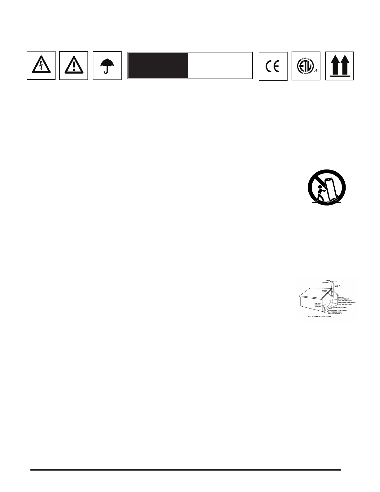
CARRITO: Si el producto va sobre un carrito, debe moverse el conjunto con cuidado. Detenciones bruscas, una fuerza excesiva o
superficies inadecuadas pueden provocar la caída de todo el conjunto. Véase Figura A.
VENTILACIÓN: Las aperturas y ranuras de la carcasa están diseñadas para la ventilación, aseguran un manejo fiable y lo protegen
de cualquier sobrecalentamiento, por tanto, nunca deben cubrirse ni bloquearse. Estas aperturas no deben taparse colocando el
producto sobre un sofá, una cama, una alfombra o superficies similares. Nunca debe colocarse en una estructura prefabricada, como una caja o un rack, a
menos que tengan la ventilación adecuada o lo permitan las instrucciones del fabricante.
FUENTES DE ALIMENTACIÓN: Esta unidad debe utilizarse exclusivamente con el tipo de suministro eléctrico indicado en la etiqueta correspondiente. Consúl-
telo antes de enchufar el producto si no está seguro del tipo de suministro del lugar donde lo va a usar.
UBICACIÓN: Este aparato debe colocarse en una ubicación estable.
PERIODOS SIN USARLO: Si no se va a usar la unidad durante un tiempo prolongado, desenchúfelo de la corriente eléctrica.
TOMA DE TIERRA O POLARIZACIÓN:
- Si este producto lleva una clavija de corriente alterna polarizada (con un pivote más grueso que otro, tipo inglés), sólo entrará en una posición. Es una medida
de seguridad. Si no puede introducir la cla-vija en el enchufe, gírela. En ningún caso debe forzarse. Si sigue sin entrar, un electricista debería cambiar el enchufe.
- Si la unidad lleva una clavija con tres pivotes (el tercero corres-ponde a la toma de tierra), sólo entrará en un tipo de enchufe. Se trata de una medida de se-
guridad. Si el enchufe y la clavija no son compatibles, un electricista deberá cambiar el enchufe. En ningún caso deberá forzarse.
PROTECCIÓN DEL CABLE DE CORRIENTE: Los cables de corriente deben protegerse para que nadie los pise ni corran el riesgo
de pinzarse por elementos colocados encima o que los aprisionen. Debe prestarse especial atención al cable, al enchufe, a los ex-
tensores de cable y al punto por donde el cable sale de la unidad.
TIERRA DE LA ANTENA EXTERIOR: Si el producto lleva conectada una antena exterior o sistema de cables, asegúrese de que
cuenta con la toma de tierra correspondiente, a fin de proteger la unidad de variaciones de voltaje y cargas de electricidad estática.
Existe documentación oficial acerca de la correcta utilización de la toma de tierra y de las medidas de seguridad pertinentes, conex-
ión de los electrodos de descarga y sus requisitos. Véase Figura B.
RAYOS: Como protección adicional del producto durante una tormenta eléctrica, o durante periodos prolongados sin usarlo, des-
enchúfelo de la corriente y desconecte la antena o sistema de cables. De este modo se protegerá el producto de los daños que
pueda producir la caída de un rayo o las fluctuaciones de la red eléctrica.
LÍNEAS ELÉCTRICAS: Nunca debe situarse un sistema de antena cerca de líneas eléctricas u otros circuitos de corriente. Tam-
poco debe colocarse en lugares donde pueda caer sobre dichos circuitos eléctricos. Al instalar un sistema de antenización exterior, debe tomarse la extrema
precaución de no tocar dichas líneas eléctricas, pues el mas minimo contacto puede ser fatal.
SOBRECARGA: No sobrecargue los enchufes de la pared con ladrones o instalando enchufes múltiples, pues correría el riesgo de electrocución o incendio.
ENTRADA DE OBJETOS O LÍQUIDOS: Nunca introduzca objetos de ningún tipo en el interior del producto, pues podrían tocar una parte eléctrica y cortocir-
cuitar el aparato, lo que resultaría en un incendio o descarga eléctrica. No verter nunca ningún líquido sobre el producto.
REPARACIÓN: No intente reparar el producto por cuenta propia, ya que abrir o retirar la carcasa le expondría a un voltaje peligroso u otros peligros. Diríjase
siempre a un centro de servicio técnico autorizado.
DAÑOS QUE REQUIEREN REPARACIÓN: Desenchufe el aparato de la corriente y diríjase a un servicio técnico autorizado si se da alguna de las siguientes
situaciones:
- El cable de alimentación o la clavija están dañados.
- Se ha vertido líquido o ha caído algún objeto sobre la unidad.
- El aparato se ha expuesto a la lluvia o a salpicaduras.
- La unidad se ha caído al suelo o dañado de algún modo.
- El aparato no funciona con normalidad, ni aun siguiendo las instrucciones. Ajuste sólo los mandos que se indican en las instrucciones, ja que la manipulación
inadecuada de otros controles podría dañar la unidad y requeriría un mayor trabajo de un técnico para restablecer su funcionamiento normal.
- Si el producto muestra anomalías en su funcionamiento, necesita revisión por parte de un servicio técnico autorizado.
RECAMBIOS: Cuando se necesite alguna pieza de recambio, asegúrese de que el servicio técnico utilice piezas originales autori-zadas o que tengan las mismas
características que las originales. Los reemplazos no autorizados pueden causar descargas eléctricas, incendios u otros daños.
COMPROBACIÓN DE SEGURIDAD: Tras la reparación, solicite al técnico que efectúe las comprobaciones de seguridad necesarias para determinar que el pro-
ducto se encuentra en las condiciones adecuadas para su funcionamiento.
MONTAJE EN UNA PARED O TECHO: Este producto nunca debe montarse en una pared o en el techo.
CALOR: Este producto debe alejarse de fuentes de calor, como radiadores, estufas u otros aparatos que irradien calor, incluyendo amplificadores.
POR FAVOR LEA ANTES DE UTILIZAR,
INSTRUCCIONES IMPORTANTES DE SEGURIDAD
Fig. B
Fig. A
PRECAUCIÓN RIESGO DE SHOCK
ELECTRICO - NO
ABRIR!

1
7
2
346
7
8
10
12
13
15 16
17
18
19 20 22
11
23
9
21
PANEL
FRONTAL
6
5
14
iTRAX BLACK
PANEL
SUPERIOR
PANEL
TRASERO

8
1
6
7
8
10
11
12
Felicidades ha adquirido la CONSOLA iTRAX MEZCLADOR
iPod®. El iTRAX, por su elegancia y su fácil manejo, es un
mezclador para Dj de gran calidad que puede usarse de muy
diversas maneras. Con un adecuado uso y mantenimiento, le
proporcionará años de solido trabajo y confianza.
- Doble enclave para reproductores Apple® iPod®
- Puerto USB con interruptor para el control de la biblioteca via PC
- Entradas 2 Phono/Line convertibles para usar con aparatos adicionales
- Salida de video compuesto para usar con iPod® compatible foto/video
- 3-Bandas EQ rotativo con ganancia y cut por canal
- Entrada Mic ¼" (6.35mm) con controles 2-Bandas EQ
- Salidas Master y Grabación RCA
- Interruptores de selección de Entrada
- Sección de Cue con fader de cue CH1/CH2
- X-Fader reemplazable por el usuario.
- Ligero, diseño ultrafino para una completa portabilidad
1.Todas las instrucciones deberán ser leídas antes de usar este
equipo.
2.Para evitar el riesgo de shock electric, no abrir la unidad. Por
favor contacte con un servicio técnico Gemini especializado.
3.No exponer esta unidad al Sol directo o fuentes térmicas di-
rectas tales como radiadores o estufas.
4. No use disolventes químicos para limpiar la unidad. Limpiar
solamente con un trapo húmedo.
5. Cuando traslade el equipo póngalo en su caja original. Esto re-
ducirá el riesgo de dañar la unidad durante el transporte.
6. ESTE APARATO NO DEBE EXPONERSE A CHORROS O
SALPICADURAS.
7.NO USE SPRAYS LIMPIADORES O LUBRICANTES EN LOS
CONTROLES,INTERRUPTORES O CUBIERTAS DEL EQUIPO
ENTRADA DE CORRIENTE AC: localizada en la parte posterior de
la unidad, es la conexión que acepta el cable de la corriente de la
unidad.
INTERRUPTOR GENERAL: Enciende o apaga la unidad. Ase-
gurese que el interruptor está en la posición “OFF” antes de realizar
cualquier conexión.
SALIDAS RCA MASTER: Estas salidas de audio son para señales
de audio no balanceadas del Master del mezclador. El CONTROL
DE VOLUMEN MASTER determina el nivel de audio que se envia
por las salidas.
SALIDAS RCA PARA GRABACIÓN: Estas salidas son para la
conexión de grabadoras, no son alterados por el CONTROL DE
VOLUMEN MASTER. Este se utiliza en directo para modificar el
volumen de la salida general, pero sin afectar al nivel del audio exis-
tente en la grabadora. Si usted no esta utilizando una grabadora,
estas salidas puden utilizarse para dirigir señal hacia el amplificador
o el sistema de altavoces, pero el volumen funcionará
independientemente del CONTROL DE VOLUMEN MASTER.
2
3
4
ENTRADAS CONVERTIBLE PHONO/LINEA La iTRAX tiene 2 EN-
TRADAS CONVERTIBLE PHONO/LINEA (PH/LN) POR RCA Los
interruptores emplazados a la derecha de las entradas RCA de
canales 1 y 2 permiten elegir entre PHONO (Giradiscos) o LINEA
(Mp3, CD, cassette etc...) y deben situarse en su correcta posición.
Cuando están en posición PH puede conectar cualquier giradiscos
con cápsula magnética, acordándose de conectar la masa (ver
conexión de TOMA DE TIERRA) o podría haber zumbidos
ENTRADAS DE CANAL: Ahora puede conectar los RCA desde su
fuente de sonido a sus respectivos CANALES (CH) de entrada del
mezclador.
NOTA: CONECTANDO UN APARATO DE LINEA EN UNA ENTRADA DE PH PUEDE
CREAR SOBRECARGA DEL MEZCLADOR Y DISTORSIÓN
TORNILLO TOMA DE TIERRA: Cuando se use con giradiscos,
necesitará conectar el cable de tierra del RCA y atornillarlo a la
TOMA DE TIERRA de la parte trasera del iTRAX Junte la línea de
tierra de PHONO (giradiscos) al tornillo posterior de TOMA DE
TIERRA que está situada en la parte central trasera del equipo.
ENTRADA USB: Este puerto permite usar su iTRAX con sus iPods
enclavados. Usando un cable USB estándard de tipo A-to-B, conecte
el iTRAX a un ordenador personal. Insertando su iPod dentro del
ENCLAVE iPod®, podrá acceder a través de su PC, para utilizar re-
copilaciones de música. El iPod® al cual esta accediendo a través
de la ENTRADA USB esta determinado por la posición del interrup-
tor de SELECCIÓN DE USB iPod 1/iPod 2.
Si hay un iPod® conectado a tu PC por la ENTRADA USB,
deberás desconectarlo correctamente, y quitar el cable de USB
antes de mover el interruptor de SELECCIÓN DE USB iPod 1/iPod 2
Una vez hecho, podrás volver a conectar el cable USB y controlar la
música del iPod® opuesto. Por favor si usa iPods conjuntamente
con software iTunes™, debe inutilizar la función actualización au-
tomática para evitar que iTunes™ borre su música durante la sin-
cronización! Gemini no se hace responsable de borrados
accidentales por incorrecta configuración de iTunes™!
ENCLAVE iPod® y ADAPTADOR DE ENCLAVE: En conjunción con
el ADAPTADOR DE ENCLAVE, el ENCLAVE iPod® es donde
cualquier iPod® se conecta con el mezclador tanto alimentarlo como
para audio.
Cuando todas sus conexiones estén realizadas, encienda el
mixer pulsando el INTERRUPTOR DE ALIMENTACIÓN..
9
iTRAX BLACK
5
13
IN THE USA ~ IF YOU EXPERIENCE PROBLEMS WITH THIS UNIT CALL GEMINI CUSTOMER SERVICE
AT: 1 (732) 346-0061. DO NOT ATTEMPT TO RETURN THISE EQUIPMENT TO YOUR DEALER.
SELECTOR ENTRADA CANALES: El Selector de ENTRADA de
CANALES permite escoger que entrada será controlada por el
FADER.
Por ejemplo en el CANAL (1) el SELECTOR de ENTRADA permite
escoger entre iPod® 1 y LINE 1 , y también en el CANAL (2) el
SELECTOR de ENTRADA permite escoger entre iPod® 2 y
LINE 2.
SALIDA MASTER: El control rotativo de SALIDA MASTER ajusta
el volumen de salida de la señal MASTER.
GANACIA ROTATIVA DE CANAL: La GANACIA ROTATIVA DE
CANAL permite aumentar la señal de cada canal individual dependi-
endo de qué nivel de entrada sea.
INTRODUCCION:
CARACTERÍSTICAS:
PRECAUCIONES:
CONEXIONES:CONTROLES:

ECUALIZACION DE 3 BANDAS: El ECUALIZACION DE 3 BAN-
DAS ajusta el tono de cada CANALES dando la opción de 3 fre-
cuencias (BANDAS) para ajustar GRAVES, MEDIOS (MID) y
AGUDOS,puede usar este ajuste para aumentar o disminuir las 3
frecuencias por separado hasta que el tono del programa musical
sea el apropiado para la escucha.
VU METER: La iTRAX tiene un VU METER estéreo que permite
monitorizar el nivel de decibelios de las salidas IZQUIERDA y
DERECHA MASTER.
VOLUMEN DE CANAL: Después de elegir que entrada desea con
el SELECTOR DE ENTRADA el correspondiente FADER DE
CANAL le permitirá ajustar el volumen de ese CANAL en
particular.
CROSSFADER: El CROSSFADER permite mezclar de una fuente
a otra. En la iTRAX el CROSSFADER es asignable entre los
canales (1) y (2) dependiendo de la posición del botón de asi-
gnación del crossfader (ver arriba) CROSS FADER del iTRAX es
reemplazable en caso de que fuera necesario. El CROSS FADER
RG-45 (RAILGLIDE™) DE DOBLE RAIL, que tiene internamente
dos guías de acero que permiten un desplazamiento suave y pre-
ciso de fin a fin puede comprarse como accesorio en cualquier dis-
tribuidor GEMINI.
ENTRADA MICRÓFONO DE 1/4”: Se encuentra en el frontal del
mezclador, y se usa para la conexión de micrófonos con conector
jack de 1/4”.Esta salida esta controlada exclusivamente por los
controles de volumen y EQ que hay a la derecha del jack.
VOLUMEN MICROFONO: Permite ajustar el volumen del micró-
fono.
EQ MICROFONO: La sección EQ del MICROFONO le permite
controlar los tonos altos y bajos de la señal de micrófono.
SELECTOR CUE DE CANAL: permite elegir que canal va a moni-
torizar por los auriculares, a la izquierda es CANAL (1) a la
derecha es CANAL (2)
VOLUMEN DE CUE: El CONTROL ROTATIVO DE VOLUMEN DE
CUE ajusta el volumen de salida de sus AURICULARES
MONITOR.
14
15
16
17
18
19
20
21
22
23
9
REEMPLAZAR EL CROSSFADER
1. Quitar los tornillos en la parte trasera de la
unidad utilizando el apropiado destornillador
2. Para quitar el botón FADER DE SELECCIÓN
DE CUE, simplemente estire firmemente el botón
hacia fuera.
3. Quitar la cubierta trásera del mezclador, y
desconectar de la tarjeta del circuito impreso
que se aloja en el X-FADER, junto con la en-
trada de micrófono de jack de 1/4”, Volumen
de Micrófono, LED Indicador On/Off del Mi-
crófono, Controles de EQ del Micrófono, y
Sección de Cue.
4. Quitar los tornillos que se encuentran a la
izquierda y derecha del X-FADER y quita el
botón del fader. Ahora puedes quitar comple-
tamente el fader.
5. Retira la carátula para reemplazar el fader
en la dirección correcta, simplemente vuelve a
conectar el botón del fader monta y asegura el
fader mediante los tornillos. Recoloca la placa
de circuito impreso con cuidado en su posi-
ción original.
6. Cuidadosamente coloca la cubierta trásera,
y los tornillos. Asegurate que este bien coloca-
dos los tornillos. Si la unidad no se cierra ade-
cuadamente, examina la colocación de la
placa del circuito del X-FADER.
Entradas:
Phono...........................................................................3 mV, 47 KOhm
Linea.........................................................................150 mV, 27 KOhm
MIC.........................................................1.5 mV, 1 K Ohm Balanceada
MIC Agudos................................................................................± 12dB
MIC Graves................................................................................± 12dB
Entrada USB.....................................................USB 2.0/1.1/1.0 Tipo B
Salidas:
Master RCA..............................................................0 dB 1V, 400 Ohm
Max.....................................................................................20V de Pico
Grabación...................................................................225 mV, 5 KOhm
General:
Respuesta en Frecuencia..................................20Hz - 20KHz +/- 2 dB
Distorsión..........................................................................menor 0.02%
Relación Señal/Ruido...................................................Mayor de 80 dB
Impedancia Auriculares.............................................................16 Ohm
Alimentación...................................Adaptador 115v 60Hz/15v AC 1.5A
.......................................................Adaptador 230v 50Hz/15v AC 1.5A
PESOS Y MEDIDAS:
Medidas: 12.5 x 4.2 x 14” (318 x 107 x 356 mm)
Peso Unitario: 12 lbs (5.44 kg)
ESPECIFICACIONES SUJETAS A CAMBIO SIN
PREVIO AVISO POR RAZONES DE MEJORA.
12
3 4
65
iTRAX BLACK
CONTROLES:
ESPECIFICACIONES:
SALIDA de AURICULARES: La SALIDA de AURICULARES local-
izada en la parte frontal de la iTRAX acepta cualquier auricular con
un conector standard 1/4” o adaptador y permite escuchar la mezcla,

ATTENTION: Cet appareil répond aux certifications FCC lorsqu'il est connecté à d'autres appareils à l'aide de cordons blindés. Afin de prévenir tout risque de parasites élec-
tromagnétiques avec un poste radio ou TV, veuillez utiliser des cordons blindés.
Le point d'exclamation situé dans un triangle est destiné à attirer votre attention durant l'utilisation de votre appareil ou d'un entretien périodique de ce dernier. Vous en trou-
verez plusieurs dans le mode d'emploi de l'appareil.
LIRE LES INSTRUCTIONS: Toutes les instructions et consignes d'utilisation doivent être lues avant l'utilisation de l'appareil.
CONSERVEZ LES INSTRUCTIONS: Nous vous recommandons de conserver les instructions et consignes d'utilisation en cas de nécessité ultérieure.
RESPECT DES CONDITIONS D'UTILISATION: Nous vous recommandons de respecter les instructions d'utilisation.
SUIVRE LES INSTRUCTIONS D'UTILISATION: Nous vous recommandons de respecter la chronologie des instructions d'utilisation.
NETTOYAGE: L'appareil doit être nettoyé avec un chiffon légèrement humide. Ne pas utiliser de produits chimiques corrosifs & volatiles (cire, essence, insecticide…) afin de
ne pas endommager l'appareil.
CORDON: Ne pas utiliser de cordons non préconisés par le fabricant afin de ne pas endommager l'appareil.
EAU & HUMIDITE: Ne pas utiliser l'appareil à proximité d'une source d'eau (cuisine, salle de bain, lavabo…), ni dans un endroit sujet à l'humidité (piscine…).
ACCESSOIRES: Ne pas installer cet appareil sur un support ou dans un endroit instable. L'appareil pourrait tomber au risque de blesser une personne et être endommagé.
Veiller à utiliser des accessoires (Pied, support, crochet..) recommandés par le fournisseur ou vendu avec l'appareil. Tout montage ou installation doit respecter les instruc-
tions du fabricant et utiliser des accessoires d'installation recommandés par le fabricant.
TRANSPORT SUR CHARIOT: Tout produit installé sur un chariot doit être manipulé avec précaution. Un déplacement brusque ou trop rapide sur une surface non plane
pourrait entraîner la chute de l'ensemble et endommager l'appareil. Voir Figure A.
VENTILATION: Les ouvertures et ouïes d'aération situées sur l'appareil permettent une ventilation optimale de ce dernier afin d'éviter toute surchauffe. Ces ouvertures ne
doivent jamais être obstruées. Ne pas placer l'appareil sur un support souple risquant de bloquer les ouïes d'aération (Lit, sofa, canapé…). Si l'appareil est intégré dans une
installation ou dans un rack, veillez à la ventilation et consultez le fabricant pour toute information complémentaire.
ALIMENTATION: Veillez à respecter la tension d'alimentation située au dos de l'appareil. Si vous n'êtes pas certain de la tension d'utilisation dans votre pays, contactez
votre revendeur.
EMPLACEMENT: Veillez à installer l'appareil sur un support stable.
PERIODE DE NON UTILISATION: Débranchez le cordon d'alimentation de l'appareil en cas de non utilisation prolongée.
MISE A LA TERRE:
- Si l'appareil est équipé d'une alimentation à courant alternatif (Prise possédant un contact plus large que l'autre), celle-ci se connectera
correctement à la prise uniquement si vous respectez le sens de branchement. Il s'agit là d'une mesure de sécurité. Si vous n'arrivez pas à
insérer la fiche dans la prise, inversez la fiche. Si vous ne pouvez toujours pas insérer cette dernière, contactez un électricien afin de rem-
placer votre prise électrique qui est obsolète. Veillez à respecter cette consigne.
- Si l'appareil est équipé d'une fiche d'alimentation avec terre, veillez à la connecter à une prise électrique équipée d'une connexion à la
terre. Il s'agit d'une mesure de sécurité. Si vous ne pouvez insérer la fiche dans la prise électrique, contactez un électricien afin de remplacer
votre prise électrique qui est obsolète. Il est important de respecter cette mesure de sécurité.
INSTALLATION DU CORDON D'ALIMENTATION: Les cordons d'alimentation doivent être déroulés et rangés proprement afin d'éviter de se
prendre les pieds dedans, en particulier les cordons reliés aux prises électriques.
ANTENNE EXTERIEURE: Si vous reliez votre appareil à une antenne ou un câble extérieur, assurez-vous de la présence d'une connexion à la terre afin d'éviter les surten-
sions et les décharges d'électricité statique. L'article 810 du National Electrical Code, ANSI/NFPAS 70, précise toutes les informations nécessaires afin d'effectuer correcte-
ment le branchement à la terre du pylône ou de la structure porteuse, la connexion du câble à l'antenne de décharge, dimensions des connecteurs de mise à la terre,
connexions des électrodes, consignes de mise à la terre des électrodes. Voir Schéma B.
ORAGE/FOUDRE: En cas d'orage et de non utilisation prolongée, débranchez le cordon d'alimentation, le câble d'antenne et les cordons audio. Ceci afin d'éviter les dégâts
occasionnés par la foudre et les surcharges électriques.
LIGNES ELECTRIQUES: Une antenne extérieure ne doit pas être située à proximité immédiate de lignes électriques et/ou d'un transformateur électrique, afin de ne pas
tomber dessus en cas de chute. Lors de l'installation d'une antenne extérieure, veillez à éviter tout contact avec des lignes électriques : tout contact peut être fatal.
SURCHARGE: Ne surchargez pas les prises électriques, blocs multiprises & rallonges en y connectant trop d'appareils. Ceci afin d'éviter tout
risque de surcharge électrique ou d'incendie (Surchauffe).
INSERTION D'OBJET & DE LIQUIDE: N'insérez pas d'objets dans les fentes ou ouvertures de l'appareil afin d'éviter tout risque de choc
électrique et d'incendie. Ne jamais renverser de liquide sur l'appareil.
SERVICE APRES VENTE: N'essayez pas de réparer cet appareil ; en l'ouvrant ou en le démontant afin d'éviter tout risque de choc élec-
trique. En cas de problème, veuillez prendre contact avec votre revendeur.
PANNE/SITUATION NECESSITANT UN RETOUR EN SAV: Débranchez l'appareil de la prise électrique, remettez le dans son emballage
d'origine et contactez votre revendeur en tenant compte des situations suivantes :
- Lorsque le cordon d'alimentation est endommagé.
- Si un liquide a été renversé dessus.
- Si l'appareil a été exposé à la pluie.
- Si l'appareil ne fonctionne pas correctement malgré le respect des instructions d'utilisation. Ajustez uniquement les réglages préconisés dans le mode d'emploi, toute ma-
nipulation ou réglage non conseillés dans ce dernier peut endommager l'appareil et procurer plus de travail en cas d'intervention SAV afin de remettre l'appareil en état de
marche.
PIECES DE RECHANGE: Lorsque vous avez besoin de remplacer des pièces de l'appareil, veillez à utiliser des pièces d'origine ou possédant des caractéristiques iden-
tiques. L'utilisation de pièces non autorisées peut endommager l'appareil : surchauffe, court-circuit, choc électrique…
CONTROLE DE SECURITE: Avant de récupérer votre appareil, assurez vous que le SAV a effectué tous les contrôles de sécurité nécessaires afin de vous restituer un ap-
pareil en état de marche.
INSTALLATION AU PLAFOND OU SUR UN MUR: Ce type d'installation est déconseillé.
CHALEUR: Veillez à installer l'appareil loin de toute source de chaleur telle que radiateur, réchaud ou tout autre appareil produisant de la chaleur.
recyclage: Cet appareil ne doit pas être considéré comme un déchet domestique à usage unique. Vous devez le déposer dans un point de collecte destiné au recyclage des
appareils électroniques et électroménagers. AInsi vous préserverez l'environnement et éviterez les problêmes de santé publique vis à vis de conséquences négatives; liées à
leur dépôt dans un endroit non approprié. Le recyclage contribue à préserver les ressources naturelles. Pour plus d'informations sur les conditions de recyclage de l'appareil,
veuillez contacter les autorités de votre pays, les institutions locales ou votre revendeur.
AVANT TOUTE UTILISATION DE L'APPAREIL, MERCI DE PRENDRE CONNAISSANCE DES INSTRUCTIONS
D'UTILISATION & DE SECURITE! RISQUE DE CHOC ÉLECTRIQUE, NE PAS OUVRIR!
ATTENTION
RISQUE DE CHOC
ÉLECTRIQUE
NE PAS OUVRIR!
Fig. A
Fig. B
10

iTrax Black
1
11
2
346
7
8
10
12
13
15 16
17
18
19 20 22
11
23
9
21
6
5
14
FACE
SUPERIEURE
FACE
ARRIERE
FACE
AVANT

INTRODUCTION:
12
PRECAUTIONS:
CONNEXIONS:
1
6
7
CONTROLS:
8
10
11
12
Nos félicitations pour l’achat du mixeur Gemini iTRAX. Cette table de mix-
age a été conçue grâce aux dernières avancées technologiques et dispose
d’une garantie de 1 ans, à l’exception du crossfader dont la garantie est de
90 jours. Avant tout utilisation, merci de lire attentivement les instructions de
ce manuel.
- Station d'accueil pour baladeurs numériques Apple® iPod®
- Port USB permettant la gestion des fichiers musicaux via PC
- 2 voies commutables Phono/Ligne pour connexion de tout autre appareil audio
- Sortie vidéo composite (Fichiers photo/video iPod®)
- Gain & correction paramétrique 3 bandes sur chaque voie
- Entrée micro sur Jack 6.35mm avec correction paramétrique 2 bandes
- Sorties Master & Enregistrement sur connecteurs RCA
- Sélection des sources
- Préécoute des voies 1 & 2 (Cue fader)
- Crossfader remplaçable par l'utilisateur
- Design compact & léger idéal pour les utilisateurs nomades
1. Toutes les instructions de fonctionnement doivent être lues avant l’u-
tilisation du matériel.
2. Afin de réduire le risque de choc électrique, n’ouvrez pas l’appareil.
Veuillez soumettre l’entretien et la réparation au service après vente de
GCI Technologies.
3. Ne pas exposer directemement cet appareil aux rayons du soleil ou à
une autre source de chaleur, tel qu’un radiateur ou un poêle.
4. Cet appareil doit être exclusivement nettoyé avec un chiffon légère-
ment humide. Proscrire solvants et autres détergents.
5. Lors du déplacement du matériel, celui-ci doit être emballé dans son
carton d’origine avec ses polystirènes de protection afin de limiter les
risques de dégâts lors de tout transport.
6. NE PAS EXPOSER CET APPAREIL A LA PLUIE OU A L’HUMIDITE.
7. N’UTILISEZ PAS DE PRODUITS DE NETTOYAGE OU LUBRIFIANT
EN VAPORISATEUR SUR AUCUN DES BOUTONS OU INTERRUP-
TEURS.
EMBASE POUR ALIMENTATION AC: L’EMBASE POUR ALIMEN-
TATION AC, situé à l’arrière de l’appareil, permet de brancher le
cordon d’alimentation (Livré avec l’appareil).
INTERRUPTEUR DE MISE SOUS TENSION: L’INTERRUPTEUR
DE MISE SOUS TENSION permet d’allumer (ON) ou d’éteindre
l’appareil (OFF). Mettre l’appareil hors tension (Position OFF) avant
d’effectuer toute connexion
Sortie MASTER RCA OUTPUT: La sortie MASTER RCA OUTPUT
sert à relier la console à l’amplificateur de puissance.
SORTIE ENREGISTREMENT RCA: Cette sortie permet de
brancher un appareil d’enregistrement. Elle est indépendante des
manipulations du CONTROLE DE VOLUME MASTER, Ceci permet
de modifier, si nécessaire, le niveau audio général sans affecter le
niveau d’enregistrement.
2
3
4
Entrées sélectionnables PHONO/LINE INPUTS: La iTRAX dispose
de 2 entrées sélectionnables PHONO/LINE (PH/LN) RCA INPUTS :
Ces petits commutateurs placés à droite des entrées RCA pour les
canaux 1 & 2 vous permettent de choisir le niveau d’entrée. Soit
PHONO (Pour platine vinyle équipée de cellule magnétique), soit
LIGNE (Pour tous les autres types de source: MP3, CD, K7...). Si vous
avez sélectionné la position PH (Phono) pour utiliser une platine
vinyle, n’oubliez pas de connecter le fil de masse (GROUNDING
SCREW).
ENTREES: Maintenant que vous savez quel type d’appareil doit être
connecté aux entrées PH ou LN, choisissez la position de vos sources
par rapport aux canaux CH1 ou CH2
NOTE: SI VOUS CONNECTEZ UN APPAREIL DE NIVEAU LIGNE SUR UNE ENTREE
COMMUTEE EN NIVEAU PHONO, LE SON SERA SATURE ET DISTORDU.
VIS DE MASSE (GROUNDING SCREW): Une vis permettant la mise
à la masse de la platine vinyle est située sur le panneau arrière. Cette
connexion est obligatoire pour l’utilisation de toute(s) platine(s)
vinyle(s). Ne pas brancher la masse de celles-ci provoquera un bour-
donnement lors de l’écoute.
ENTRÉE USB: Permet d’utiliser votre iTRAX comme station d’ac-
cueil pour vos baladeurs iPods. Utilisez un câble standard USB A-B,
connectez l’ iTRAX à votre ordinateur. Après avoir inséré votre iPod
dans son emplacement iPod DOCK (1), vous pouvez accéder à ce
dernier via votre PC (Gestion des fichiers musicaux...).
Pour sélectionner lequel des 2 iPods sera géré par l’ENTRÉE USB,
vous devez régler le COMMUTATEUR iPod 1/iPod 2 USB sur l’une
des deux positions. Veuillez noter que si vous utilisez plusieurs
iPods, et ce simultanément avec le logiciel iTunes, vous devrez
d’abord annuler la fonction de mise à jour automatique afin d’éviter
qu’iTunes efface vos fichiers musicaux durant la synchronisation!
Gemini ne peut être tenu pour responsable d’une mauvaise configu-
ration
EMPLACEMENTS POUR iPod & ADAPTATEURS: Emplacements
permettant de connecter les baladeurs iPods au iTRAX (Connexion
audio & Alimentation électrique). Choisissez les adaptateurs en fonc-
tion des modèles iPods utilisés.
Une fois que tous vos branchements sont effectués, appuyez sur
la touche POWER (1) pour la mise sous tension.
9
iTrax BLACK
5
13
AUX USA ~ EN CAS DE PROBLEME AVEC L’APPAREIL, CONTACTEZ LE SERVICE TECHNIQUE
DE GEMINI AU: 1 (732) 346-0061. NE RENVOYEZ PAS L’APPAREIL A VOTRE REVENDEUR.
SELECTEUR D’ENTREES: Les sélecteurs d’entrées vous permettent
d’assigner chaque source au canal désiré.
Exemple: Pour le canal 1, le sélecteur d’entrées vous donne le choix
entre iPod® 1 et LINE 1. De la même manière pour le canal 2, le
sélecteur vous offre la possibilité de choisir entre iPod® 2 et LINE 2.
VOLUME SORTIE MASTER (SORTIE PRINCIPALE): Le poten-
tiomètre rotatif VOLUME SORTIE MASTER permet de régler le niveau
de la SORTIE MASTER.
REGLAGE DE GAIN: Le réglage de gain - individuel par canal - per-
met d’ajuster le niveau du signal musical entrant dans votre mixeur et
ce, indépendamment des réglages HIGH (AIGU) / MID (MEDIUM) /
LOW (GRAVE).
CARACTERISTIQUES:

EGALISATION 3 BANDES (CORRECTIONS PARAMETRIQUES)
L’égalisateur 3 bandes par canal, sert à modifier la tonalité de votre
morceau musical. 3 réglages indépendants: AIGU ( HIGH), MEDIUM
(MID) & GRAVE ( LOW).
VU-METRE La iTRAX possède un vu-mètre permettant d’indiquer
les niveaux stéréo gauche et droite de la sortie MASTER ou les
niveaux d’entrée res pectifs des différents canaux.
FADER DE VOLUME DE VOIE: Après avoir affecté vos sources sur
vos 2 canaux, réglez le volume de chaque canal grâce à ce poten-
tiomètre rectiligne (Fader). Grâce à ces faders vous pourrez mélanger
vos sources.
CROSSFADER: Le CROSSFADER permet de passer d’une source à
une autre. Le crossfader de votre appareil est amovible et remplaçable
facilement par l’utilisateur. Cet appareil est équipé d’un crossfader
RG-45 (RAILGLIDE™). Vous pouvez , si vous le désirez, équiper votre
mixeur d’un crossfader RG-45 ( RAILGLIDE™) possédant une courbe
et un coupure plus appropriée au scratch. Cette pièce est disponible
auprès de tout revendeur agréé GEMINI.
ENTRÉE MICRO SUR PRISE JACK 6.35MM: Cette entrée située
en face avant permet de connecter un microphone équipé d’un con-
necteur Jack 6.35mm. Cette entrée est gérée par les réglages situés
à droite de l’embase JACK 6.35MM (Volume & Corrections
Paramétriques).
VOLUME MICROPHONE:Permet d’ajuster le volume du microphone.
MICROPHONE EQ: Les réglages EQ MICROPHONE (11) vous per-
mettent d’ajuster les fréquences aigues et basses de votre micro.
SELECTION DE PRE-ECOUTE (CUE): La touche de SELECTION DE
PRE-ECOUTE (CUE) permet de choisir la voie que vous souhaitez
pré-écouter dans votre casque.
VOLUME CASQUE (CUE): Le potentiomètre rotatif VOLUME
CASQUE permet de régler le niveau de votre CASQUE.
SORTIE CASQUE (HEADPHONE OUTPUT) La sortie casque
HEADPHONE OUTPUT est située en face avant de votre
iTRAX En branchant votre casque (JACK 6,35mm), vous pouvez
écouter le canal 1, le canal 2 ou le canal 3 et ainsi préparer votre
morceau musical avant de le jouer. Le volume de la sortie casque est
réglable, ainsi que la sélection du mélange des sources (CUE/PGM).
14
15
16
17
iTrax BLACK
18
19
20
21
22
23
13
FADER REPLACEMENT:
CONTROLS:
1.Enlevez les vis situées à la base de l’ap-
pareil en utilisant un tournevis approprié
2. Enlevez le bouton du potentiomètre
SÉLECTION PRÉ-ÉCOUTE en tirant
fermement dessus.
3. Enlevez la partie inférieure du châssis de
l’appareil et délogez le circuit imprimé con-
tenant le CROSSFADER, le Jack 6.35mm de
l’entrée micro, le volume micro, l’interrupteur
& la led micro On/Off, les corrections
paramétriques micro, et la section pré-
écoute.
4. Démontez les vis situées aux extrémites du
CROSSFADER (9) et débranchez le con-
necteur situé à la base du crossfader. Vous
pouvez maintenant enlever le crossfader.
5. Mettez le nouveau CROSSFADER en place
en respectant le sens d’installation, connectez
le et remettez les vis. Repositionnez le circuit
imprimé de façon identique en faisant atten-
tion.
6. Remettez la partie inférieure du châssis en
place & remettez les vis. Ne serrez pas trop
ces dernières. Si l’appareil ne se referme pas
correctement, vérifiez le positionnement du
circuit imprimé contenant le CROSSFADER.
SPECIFICATIONS:
Entrées:
Phono.........................................................................3 mV, 47 KOhms
Ligne......................................................................150 mV, 27 KOhms
MICRO.......................................................1.5 mV, 1 K Ohm Balanced
MICRO Aigu...............................................................................± 12dB
MICRO Grave............................................................................± 12dB
Entrée USB...................................................USB 2.0/1.1/1.0 (Type B)
Sorties:
Sortie Principale (Master) RCA..............................0 dB 1V, 400 Ohms
Max.............................................................................20V Crête/Crête
Sortie Enregistrement .............................................225 mV, 5 KOhms
Bande Passante................................................20Hz - 20KHz +/- 2 dB
Distorsion.................................................................................< 0.02%
Rapport Signal/Bruit..................................................................> 80 dB
Impédance Casque................................................................16 Ohms
Alimentation........................................................
Transformateur Externe .................................115v 60Hz/15v AC 1.5A
Transformateur Externe .................................230v 50Hz/15v AC 1.5A
POIDS & DIMENSIONS:
Dimensions: 12.5 x 4.2 x 14” (318 x 107 x 356 mm)
Poids de l’appareil: 12 lbs (5.44 kg)
SPECIFICATIONS SUBJECT TO CHANGE WITHOUT NOTIFICATION
FOR IMPROVEMENT
12
3 4
65

VORSICHT: Dieses Produkt erfüllt die FCC-Regeln, wenn Sie zum Anschluss abgeschirmte Kabel und Stecker verwenden, um es mit anderen Geräten zu verbinden. Auch um elektromagnetische Störun-
gen anderer elektrischer Geräte wie Radios oder Fernseher zu vermeiden, benutzen Sie abgeschirmte Kabel und Stecker für die Verbindungen.
Das Ausrufezeichen im gleichseitigen Dreieck weißt Sie in der Bedienungsanleitung auf wichtige Bedienungsanweisungen und Wartungs-/Serviceanweisungen hin.
Das Blitzsymbol im gleichseitigen Dreieck dient dazu, den Benutzer vor gefährlichen Spannungen an nicht isolierten Stellen im Gehäuse zu warnen, die so groß sind, dass sie eine Gefahr für den Be-
nutzer darstellen.
ANWEISUNGEN LESEN: Lesen Sie alle Sicherheits- und Bedienungsanweisungen, bevor Sie mit dem Produkt arbeiten.
AUFBEWAHRUNGSHINWEIS: Bewahren Sie alle Sicherheits- und Bedienungsanweisungen gut auf.
WARNHINWEISE: Alle Warnhinweise für das Produkt und die Bedienungsanweisungen müssen genau eingehalten werden.
ANWEISUNGEN BEFOLGEN: Alle Anweisungen zum Betrieb des Produkts sollten befolgt werden.
REINIGUNG: Das Produkt sollte nur mit einem Polier- oder einem weichen trockenen Tuch gereinigt werden. Benutzen Sie dazu niemals Möbelwachs, Benzine, Insektenmittel oder andere flüchtige Reini-
gungsmittel, denn Sie könnten zur Korrosion des Gehäuses führen.
ERWEITERUNGEN: Benutzen Sie keine Erweiterungen, die nicht vom Hersteller empfohlen sind, da sie zu Risiken führen könnten.
WASSER&FEUCHTIGKEIT: Benutzen Sie dieses Produkt nicht in der Nähe von Wasser, z. B. in der Nähe einer Badewanne, einer Waschschüssel, eines Küchenspülbeckens, eines Waschbeckens, in
einem feuchten Keller, in der Nähe eines Schwimmbeckens oder an ähnlichen Orten.
ZUBEHÖR: Stellen Sie das Produkt nicht auf eine wackelige oder labile Unterlage. Das Produkt könnte herunterfallen und dabei Kinder oder Erwachsene verletzen, wie auch selber beschädigt werden.
Stellen Sie das Produkt nur auf vom Hersteller empfohlene oder verkaufte Unterlagen. Jede Befestigung und Montage des Produkts sollte nach den Anweisungen des Herstellers ausgeführt werden.
Nutzen Sie dazu ein vom Hersteller empfohlenes Montageset.
MOBILE UNTERLAGEN: Bewegen Sie eine Kombination aus dem Produkt und einer mobilen Unterlage mit Vorsicht. Schnelles Anhalten, zu viel Schub oder unebene Böden können dazu führen, dass
sich Produkt und mobile Unterlage überschlagen (SIEHE FIG. A).
BELÜFTUNG: Schlitze und Öffnungen im Gehäuse sind für die Belüftung vorgesehen. Sie stellen den zuverlässigen Betrieb des Produkts sicher und schützen es vor Überhitzung. Diese Öffnungen dürfen
nicht verschlossen, blockiert oder bedeckt werden.Stellen Sie deswegen das Produkt niemals auf ein Bett, ein Sofa, einen Teppich oder Stellen mit ähnlicher Oberfläche. Wenn Sie dieses Produkt in
einer festen Installation wie z. B. in einem Regal oder einem Rack einbauen, sorgen Sie für ausreichende Belüftung oder sorgen Sie dafür, dass die Bestimmungen des Herstellers genau ein gehalten
werden.
STROMANSCHLUSS: Dieses Produkt darf nur mit dem auf dem Gerät angegebenen Strom betrieben werden. Wenn Sie sich nicht sicher sind, welche Stromart Sie bei sich zu Hause haben, fragen Sie
den Verkäufer des Geräts oder Ihren Stromversorger.
AUFSTELLUNGSORT: Stellen Sie das Gerät an einem festen Ort auf.
ZEITEN DES NICHTGEBRAUCHS: Ziehen Sie das Stromkabel aus dem Gerät heraus, wenn Sie es für eine längere Zeit nicht gebrauchen.
ERDUNG ODER POLUNG: Wenn dieses Produkt mit einem gepolten Wechselstromstecker (ein Stecker mit einem Kontakt mehr als andere Stecker) ausgestattet ist,
passt dieser nur in einer bestimmten Richtung in die Steckdose und ist ein besonderes Sicherheitsmerkmal. Sollten Sie den Stecker nicht komplett in die Steckdose
stecken können, versuchen Sie ihn andersherum einzustecken. Sollte der Stecker auch dann noch nicht in die Steckdose passen, beauftragen Sie einen Elektriker,
um diese veraltete Steckdose auszutauschen.
Wenn dieses Produkt mit einem geerdeten dreipoligen Stecker ausgestattet ist, hat der Stecker einen dritten (Erdungs-)Kontakt und passt nur in eine Steckdose mit
entsprechender Erdung. Auch das ist ein Sicherheitsmerkmal. Sollte der Stecker nicht in die Steckdose passen, beauftragen Sie einen Elektriker, um diese veraltete
Steckdose auszutauschen.
SCHUTZ DES STROMKABELS: Stromkabel sollten so verlegt werden, dass man nicht auf sie treten kann, noch dass sie von darauf stehenden oder gegen sie stoßenden Gegenständen gequetscht wer-
den. Achten Sie besonders auf Kanten, Sicherung, Stecker und Buchsen.
AUSSENANTENNENERDUNG: Wenn Sie eine Außenantenne oder ein Radio-/Fernsehkabelsignal an das Produkt anschließen, achten Sie darauf, dass die Antenne oder das Kabel geerdet sind, um
dafür zu sorgen, dass Überspannungen und elektrostatische Aufladungen nicht auftreten können. Im Artikel 810 des National Electrical Code, ANSI/NFPA 70, finden Sie Informationen über die richtige
Erdung des Antennenmasts und weitere Informationen zu diesem Thema. (SIEHE AUCH FIG. B).
GEWITTER: Trennen Sie das Produkt während eines Gewitters oder wenn es unbeaufsichtigt ist oder wenn es für eine lange Zeit nicht benutzt wird, durch herausziehen des Stromkabels aus der Netz-
dose. Trennen Sie auch die Verbindung zu einer Antenne oder Radio-/Fernsehkabeln. Dadurch vermeiden Sie Beschädigungen des Produkts durch Blitze oder Überspannungen.
STROM- UND ÜBERLANDLEITUNGEN: Stellen Sie eine Außenantenne nicht in der Nähe von Überlandleitungen, elektrischen Licht- oder Stromkreisen oder an Stellen, wo sie in eine solche Leitung
fallen könnte, auf. Wenn Sie eine Außenantenne aufstellen, achten Sie besonders darauf, dass Sie auf keinen Fall irgendwelche Stromleitungen berührt. Das kann zu gefährlichen Auswirkungen
führen.
ÜBERLASTUNG: Überlasten Sie keine Steckdosen, Verlängerungskabel oder Sicherungen. Das kann zu Bränden oder elektrischen Schlägen führen.
EINDRINGEN VON GEGENSTÄNDEN ODER FLÜSSIGKEIT: Führen Sie niemals irgendwelche Gegenstände durch Öffnungen in das Produkt ein. Sie könnten mit
Strom führenden Stellen in Verbindung kommen oder Kurzschlüsse verursachen, die zu Bränden oder elektrischen Schlägen führen können. Gießen Sie niemals
irgendwelche Flüssigkeiten auf oder in das Produkt.
SERVICE: Versuchen Sie nicht, das Produkt selber zu reparieren. Durch das Öffnen des Gehäuses oder Entfernen von Schrauben können Sie mit gefährlichen Span-
nungen oder anderen Risiken in Kontakt kommen. Beauftragen Sie im Reparaturfall nur qualifiziertes Servicepersonal.
WANN SERVICE NÖTIG IST: Unter den folgenden Bedingungen ziehen Sie auf jeden Fall das Stromkabel aus der Steckdose und beauftragen Sie für eine Reparatur
nur qualifiziertes Servicepersonal:
- Wenn das Stromkabel defekt ist.
- Wenn Flüssigkeit auf oder in das Produkt gelaufen ist oder Gegenstände in das Produkt gefallen sind.
- Wenn das Produkt Regen oder Wasser ausgesetzt war.
- Wenn das Produkt trotz Befolgen der Bedienungsanweisungen nicht normal arbeitet. Stellen Sie dabei das Produkt nur nach den Anweisungen der Bedienungsanleitung ein, andere Einstellungen
können das Produkt beschädigen und den aufwändigen Einsatz von Technikern für die Wiederherstellung erfordern.
- Wenn das Produkt hingefallen oder auf andere Art und Weise beschädigt ist.
- Wenn das Produkt eine eindeutige Veränderung im Betrieb zeigt.
ERSATZTEILE: Wenn Ihr Produkt Ersatzteile benötigt, achten Sie darauf, dass der Servicetechniker nur vom Hersteller erlaubte Ersatzteile oder Ersatzteile, die die gleichen Eigenschaften wie die origi-
nalen Teile aufweisen, einsetzt. Falsche Ersatzteile können zu Bränden, elektrischen Schlägen oder anderen Risiken führen.
SICHERHEITSTEST: Bevor der Service oder eine Reparatur für dieses Produkt beendet sind, beauftragen Sie den Servicetechniker, einen Servicetest durchzuführen, um sicher zu stellen, dass das Pro-
dukt einwandfrei funktioniert.
WAND- ODER DECKENMONTAGE: Das Produkt sollte nicht an einer Wand oder der Decke montiert werden.
HITZE: Stellen Sie das Produkt nicht in die Nähe von Wärmequellen wie Radiatoren, Wärmespeichern, Öfen oder anderen Produkten (auch Verstärker), die Hitze erzeugen.
VERWERTEN SIE WIEDER: Dieses Produkt sollte nicht als Haushaltsmüll entsorgt werden. Entsorgen Sie das Produkt im Bedarfsfall bei einer zuständigen Entsorgungsstelle, die das Recycling der elek-
trischen und elektronischen Bauteile übernimmt. Wenn Sie das Produkt dem gemäß entsorgen, schützen Sie die Umwelt und die menschliche Gesundheit. Bei nicht sachgemäßer Entsorgung
gefährden Sie die Umwelt und die menschliche Gesundheit. Das Recycling verschiedener Materialien hilft, die Natur und ihre Ressourcen zu schonen. Für nähere Informationen bezüglich der
Entsorgung dieses Produkts nehmen Sie Kontakt auf mit Ihrer lokalen Stadtverwaltung, dem zuständigen Entsorgungsunternehmen oder dem Händler, bei dem Sie das Produkt gekauft haben.
VOR BENUTZUNG DES GERÄTS LESEN. WICHTIGE HINWEISE&SICHERHEITSBESTIMMUNGEN
WARNUNG! STROMSCHLAGGE-
FAHR, nicht öffnen!
Abb. A
Abb. B
14

iTrax Black
1
15
2
346
7
8
10
12
13
15 16
17
18
19 20 22
11
23
9
21
6
5
14
OBEN
RÜCKSEITE
VORDERSEITE

16
1
6
7
REGLER:
8
10
11
12
Glückwunsch zum Kauf des Gemini iTRAX iPod® Stereomixers. Dieser
professionelle State of the art Mixer ist mit einer 1 Jahres Hersteller-
garantie*versehen, mit Ausnahme des Crossfaders. Der Crossfader ver-
fügt über eine 90 Tage Garantie. Bitte lesen Sie diese Anleitung sorgfältig
durch, bevor Sie den Mixer verwenden.reliable performance.
- Zweifache Docking-Station fur die digitalen Musikplayer Apple iPod®
- USB-Anschluss mit Dock-Schalter erlaubt die Verwaltung der Musik-
Datenbank mit dem PC
- 2 umschaltbare Phono-/Line- Eingänge fur weitere Audiogeräte
- Composite-Video-Ausgang fur iPods® mit Photo/Video-Funktion
- 3-Band Equalizer mit Drehreglern, Cut-Funktion und Gain-Regler pro Kanal
- 6,3-mm-Klinkenmikrofoneingang mit 2-Band-Equalizer mit Drehreglern
- Master- und Record-Ausgang mit Cinch-Anschlussen
- Eingangswahlschalter
- Cue-Sektion mit Cue-Fader fur Kanal 1 und 2
- Austauschbarer Crossfader
- Leichtes und frisches Design fur einfachsten Transport
1. Lesen Sie die Hinweise aufmerksam durch, bevor Sie das Gerät in Be-
trieb nehmen.
2. Um das Risiko eines elektrischen Schlages zu reduzieren, sollten Sie
das Gerät nicht öffnen. Bringen Sie das Gerät im Servicefall immer zu
einem von Gemini qualifizierten Techniker.
3. Nicht direktem Sonnenschein oder Hitzequellen wie Radiatoren oder
Öfen aussetzen.
4. Nur mit einem weichem Tuch reinigen. Keine Lösungsmittel oder
chemischen Reinigungsmittel verwenden.
5. Transportieren Sie das Gerät im Originalkarton. So verringern Sie das
Risiko eines Transportschadens.
6. NICHT REGEN ODER FEUCHTIGKEIT AUSSETZEN.
7. KEINE SPRÜHREINIGER ODER SCHMIERÖL AN REGLERN,
OBERFLÄCHE ODER SCHALTERN NUTZEN.
NETZBUCHSE: Mit der ruckseitigen NETZBUCHSE, wird das mit-
gelieferte Netzteil verbunden, um den iTrax mit Strom zu versorgen.
STROMVERSORGUNG: Das Gerät wird mit einem NETZTEIL
geliefert, das Sie zuerst in den rückseitigen NETZEINGANG
stecken und dann erst in die Steckdose.
Der MASTER Ausgang: dient zum Anschluss des Mixers an Ihren
Hauptverstärker. Benutzen Sie dazu ein Cinch Kabel.
RECORD-CINCH-AUSGÄNGE: Diese Ausgänge eignen sich am
besten, um ein Rekordinggerät daran anzuschließen, da sie nicht
vom MASTERVOLUME- REGLER beeinflusst werden. Das ist sehr
nutzlich, da Sie so während einer Live-Performance die Lautstärke
der Master-Ausgänge ändern können, ohne dass das mit aufgenom-
men wird. Wenn die Ausgänge nicht fur Aufnahmen verwendet wer-
den, können Sie daran auch einen weiteren Verstärker oder
Lautsprecher anschließen, Sie mussen die Lautstärke dafur jedoch
separat einstellen.
2
3
4
UMSCHALTBARE PHONO/LINE CINCH EINGÄNGE: Der iTRAX
verfügt über 2 UMSCHALTBARE PHONO/LINE (PH/LN) CINCH
EINGÄNGE. Mit den PH/LN SCHALTERN direkt neben des jeweili-
gen Eingangs können Sie von PHONO (Plattenspieler) nach LINE
(MP3, CD, Tape) und umgekehrt schalten.
Steht der PH/LN SCHALTER auf Phono, können Sie Plattenspieler
mit Magnetsystem anschließen. Vergessen Sie dabei nicht, diese am
Masseanschluss des iTRAX zu erden.
KANALEINGÄNGE: Haben Sie die Schalter in die richtige Position
gebracht, können Sie Ihre Player mit einem Cinch Kabel an die
Eingänge der gewünschten Kanäle anschließen.
WICHTIG: WENN SIE EIN LINE SIGNAL AN EINEN PHONO EINGANG ANSCHLIESSEN,
KANN DAS ZU ÜBERSTEUERUNGEN UND VERZERRUNGEN FÜHREN.
MASSEANSCHLUSS: Wenn Sie Plattenspieler verwenden, sollten
Sie die Cinch Kabel erden, indem Sie die Masseklemme des Cinch
Kabels mit dem rückseitigen MASSEANSCHLUSS des iTRAX
verbinden.
USB-EINGANG: Dank dieses Anschlusses können Sie den iTRAX
als Dock fu!r Ihre iPods nutzen. Verbinden Sie den iTRAX mit einem
Standard A-nach-B USB Kabel mit einem Computer. Wenn Sie einen
iPod® in das iPod® DOCK stecken, können Sie darauf mit Ihrem PC
zugreifen, um z.B. Ihre Musiksammlung zu verwalten. Der iPod, auf
den Sie u!ber den USBEINGANG mit dem Computer zugreifen kön-
nen, wird mit dem iPod 1/iPod 2 USB-WAHLSCHALTER festgelegt.
Ist ein iPod® u!ber den USB-Eingang mit Ihrem PC verbunden,
ziehen Sie ihn vorsichtig aus dem Dock heraus und entfernen Sie
das USB-Kabel, bevor Sie die Stellung des iPod® 1/iPod 2 USB-
Wahlschalters verändern. Haben Sie diesen Vorgang vollzogen kön-
nen Sie das USB-Kabel wieder anschliessen und auf dem zweiten
iPod Ihre Musik verwalten. Bitte achten Sie darauf, wenn Sie
mehrere iPods in Verbindung mit der iTunes Software verwenden
wollen, in dieser zuerst das automatische Update abzuschalten, da
iTunes während der Synchronisation sonst die Musik löschen wu!rde.
Gemini u!bernimmt keine Haftung, falls iTunes nicht
richtig konfiguriert ist!
iPod® DOCK und DOCKING LADESTATION: In Verbindung mit der
DOCKING LADESTATION wird uber das iPod® DOCK die
Verbindung zum iPod sowohl fur Audiosignale als auch fur die
Ladekapazität hergestellt.
Haben Sie alle Anschlüsse vorgenommen, können Sie den Mixer
durch Drücken der POWER TASTE einschalten.
9
iTrax BLACK
5
13
IN THE USA ~ IF YOU EXPERIENCE PROBLEMS WITH THIS UNIT CALL GEMINI CUSTOMER SERVICE AT:
1 (732) 346-0061. DO NOT ATTEMPT TO RETURN THIS EQUIPMENT TO YOUR DEALER.
KANAL EINGANGSWAHL: Mit dem KANAL
EIGANGSWAHLSCHALTER wählen Sie aus, welcher Eingang
einem Kanal zugewiesen und von diesem gesteuert wird.
Der KANAL EINGANGSWAHLSCHALTER bietet Ihnen folgende
Wahlmöglichkeiten: iPod® 1 und LINE 1, bei Kanal 2 stehen Ihnen
iPod® 2 und LINE 2 zur Verfügung.
MASTER REGLER: Der MASTER Regler stellt die Lautstärke des
MASTER Ausgangs ein.
GAIN-REGLER: Mit diesem Regler, den Sie in jedem Kanal finden,
könnenv Sie den Pegel des anliegenden Signals erhöhen oder ab-
senken. Damit ist es möglich, Signale aneinander anzugleichen oder
den Pegel zu erhöhen, wenn die Regelmöglichkeiten des
KANAL-FADERS nicht ausreichen.
EINLEITUNG:
FEATURES:
VORSICHTSMASSNAHMEN:
ANSCHLÜSSE:

3 BAND EQUALIZER: Mit dem 3 BAND EQUALIZER können Sie
die Klangfarbe jedes KANALS in 3 Frequenzen (BÄNDER) ein-
stellen. Mit den entsprechenden Reglern LOW (tiefe Frequenzen),
MID (mittlere Frequenzen) und HIGH (hohe Frequenzen) können Sie
das jeweilige Frequenzband unabhängig von den anderen anheben
oder absenken, bis Ihnen der Klang der Musik gefällt und optimal für
die jeweilige Hörumgebung ist.
PEGELANZEIGE: Der iTRAX besitzt eine Stereo PEGELANZEIGE ,
die den Pegel anzeigt.
KANALFADER: Nachdem Sie mit dem KANAL EIN-
GANGSWAHLSCHALTER den gewünschten Eingang festgelegt
haben, können Sie mit dem zugehörigen KANALFADER die Laut-
stärke dieses Kanals einstellen.
CROSSFADER: Mit dem CROSSFADER können Sie zwischen zwei
Signalen überblenden. Er kann auch durch einen RG-45 (RAIL
GLIDE™) Dual-Rail Crossfader ersetzt werden, der mit seinen bei-
den internen Gleitschienen aus rostfreiem Stahl für weiche und aku-
rate Fahrten von einem zum anderen Ende optimiert ist. Sie
erhalten die Fader bei Ihrem GEMINI Händler.
6.3-MM-KLINKEN-MIKROFONEINGANG: An diesen Eingang auf
der Oberseite des Mixers können Sie Mikrofone mit 6.3-mm-Klinken-
stecker anschließen. Die Volume- und EQ-Regler rechts von der
Klinkenbuchse dienen ausschließlich zur Kontrolle dieses Eingangs.
MIC VOLUME: Hier können Sie die Lautstärke des Mikrofonsignals
einstellen.
MIC EQ: Regeln Sie die hohen und tiefen Frequenzen des Mikro-
fonsignals mit dem MICROPHONE EQ.
CUE AUSWAHLTASTEN: Mit dem CUE AUSWAHLTASTEN legen
Sie fest, welchen Kanal Sie im Kopfhörer abhören.
CUE REGLER: Mit dem CUE VOLUME Regler stellen Sie die Laut-
stärke des KOPFHÖRER AUSGANGS ein.O
KOPFHÖRER AUSGANG: An den KOPFHÖRER AUSGANG auf
der rechten Vorderseite des iTRAX können Sie Kopfhörer mit 6,3
mm Klinkenstecker (oder Adapter) anschließen. So können Sie die
Musik vorhören (CUE), bevor Sie sie spielen. Sie können die Laut-
stärke und die Mischung regeln.
14
15
16
17
iTrax BLACK
18
19
20
21
22
23
17
CROSSFADER TAUSCHEN:
REGLER:
1. Drehen Sie die Schrauben auf der Unter-
seite des Geräts mit einem passenden
Schraubendreher heraus.
2. Entfernen Sie die Kappe des
CUE-FADERS,indem Sie ihn einfach mit den
Fingern abziehen.
4. Drehen Sie die Schrauben auf der rechten
und linken Seite des CROSSFADERS heraus
und entfernen Sie den Stecker am Boden der
Fader- Baugruppe. Jetzt kann der Fader kom-
plett abgenommen werden.
5. Achten Sie beim Einbau des Faders darauf,
ihn richtig herum einzusetzen. Stecken Sie
den Stecker auf seinen alten Platz am Boden
der Fader- Baugruppe und setzen Sie die
Schrauben ein. Nun kommt die Platine vor-
sichtig an ihren alten Platz.
6. Setzen Sie die Ruckwanne vorsichtig auf
und befestigen Sie mit den Schrauben. Achten
Sie darauf, die Schrauben nicht zu uber-
drehen. Sollte das Gehäuse nicht richtig
schließen, uberprufen Sie die Fader-Bau-
gruppe auf exakten Sitz.
SPECIFICATIONS:
Inputs:
Phono...........................................................................3 mV, 47 KOhm
Line..........................................................................150 mV, 27 KOhm
MIC............................................................1.5 mV, 1 K Ohm Balanced
MIC High....................................................................................± 12dB
MIC Low.....................................................................................± 12dB
USB Input........................................................USB 2.0/1.1/1.0 B-Type
Outputs:
Master RCA.............................................................0 dB 1V, 400 Ohm
Max..........................................................................20V Peak-to-Peak
Record.......................................................................225 mV, 5 KOhm
General:
Frequency Response........................................20Hz - 20KHz +/- 2 dB
Distortion..................................................................................< 0.02%
S/N Ratio..................................................................Better Than 80 dB
Headphone Impedance............................................................16 Ohm
Power Source....................................Adapter 115v 60Hz/15v AC 1.5A
..........................................................Adapter 230v 50Hz/15v AC 1.5A
WEIGHTS AND DIMENSIONS:
Dimensions: 12.5 x 4.2 x 14” (318 x 107 x 356 mm)
Unit Weight: 12 lbs (5.44 kg)
TECHNISCHE DATEN UND DAS DESIGN KÖNNEN ZUR VERBESSERUNG
VERÄNDERT WERDEN.*ES GELTEN DIE JEWEILIGEN
GEWÄHRLEISTUNGSBESTIMMUNGEN DES LANDES, WO
DAS GERÄT ERWORBEN WURDE.
12
3 4
65
3. Heben Sie die Ruckwanne des Mixers ab
und entfernen Sie die Platine, die den
CROSSFADER zusammen mit dem 6.3-mm-
Mikrofonklinkeneingang, dem Mic- Lautstärk-
eregler, der Mic Ein-/Aus-Anzeige, den Mic-
EQ-Reglern undder Cue-Sektion beherbergt.

E-mail Address: ___________________________________________________________________________________________________________________________________________________________________________________________________________________________________________________
Phone #:
Initial:
State: or
Last Name:
Province:
Address: (Number and Street)
City:
Apt #:
Country: Postal Code:
Model Number: (Example: CDT-05) Serial Number: (Located on back of most units)
Month Day Year
Date of Purchase:Purchase Price: .00
$
(EXCLUDING TAX)
Zip Code:
Age:
City:
or
Date of Birth
Save postage and register your product on-
line at www.geminidj.com and automati-
cally be registered for great prize
giveaways!
If you do not have internet access, fill out the form below and mail to the appropriate ad-
dress listed at the right side of this page.
Cut along this line & keep the rest of this page for your
records.
USA
GEMINI SOUND PRODUCTS
Worldwide Headquarters
1 Mayfield Ave
Edison, NJ 08837 USA
Tel: (732) 346-0061
Fax: (732) 346-0065
SPAIN
GEMINI SOUND PRODUCTS
S.A.
Rosello, 516,
08026 Barcelona, Spain
Tel: 3493-436 37 00
Fax: 3493-347-6961
FRANCE
GCI TECHNOLOGIES S.A.R.L
1, Allee d’Effiat,
Parc de l’evénement, 91160
Longjumeau, France
Tél: + 33 1 69 79 97 70
Fax: + 33 1 69 79 97 80
GERMANY
GCI TECHNOLOGIES
Liebigstr. 16,
Haus B – 3. OG,
85757 Karlsfeld
Germany
Tel: 08131 – 39171 – 0
Fax: 08131 – 39171 – 8
UK
GEMINI SOUND PRODUCTS
Unit C4
Hazleton Industrial Estate, P08
9JU Waterlooville, UK
Tel: 087 087 00880
Fax: 087 087 00990
EN FRANCE
En cas de panne, merci de contacter votre
revendeur. Tout appareil en panne doit y
être retourné, accompagné de sa facture
d'achat, de son emballage d'origine et d'un
descriptif de panne. L'appareil sera expédié
au SAV de GCI Technologies France. Tout
produit reçu sans facture sera réparé hors
garantie. L’appareil sera ensuite ré-expédié
au revendeur.
IN SPAIN
En caso de mal funcionamiento de
esta unidad, por favor contacte con el
Servicio de Atención al Cliente en el
teléfono 93 436 37 00 que le aseso-
rará sobre el procedimiento correcto
para solucionarlo. En caso de ser
necesario enviar la unidad para su
reparación, el Servicio de Atención al
Cliente le proveerá de un número de
incidencia, así como de la dirección
del Servicio de Asistencia Técnica más
cercano a su residencia.
IN THE UNITED KINGDOM
In the event that you need service on
your Gemini product under warranty,
simply write a letter describing the
problem, along with your contact in-
formation. Make sure to enclose a
copy of your receipt for proof of war-
ranty information. A return number
is not required. You will be responsi-
ble for shipping charges to Gemini
UK, and Gemini UK will pay to re-
turn the unit to you if it is considered
under warranty.
IN GERMANY
Die allgemeinen gesetzlichen
Gewährleistungen bleiben von den
Herstellergarantien unberührt. Der
Garantieanspruch erlischt bei Ein-
griffen durch den Käufer oder durch
Dritte sowie bei unsachgemässer Be-
handlung.
Gewährleistungsansprüche sind auss-
chließlich gegenüber Ihrem Fach-
händler geltend zu machen.
WARRANTY AND REPAIR:
All Gemini products are designed and manufactured to the highest
standards in the industry. With proper care and maintenance, your product
will provide years of reliable service.
LIMITED WARRANTY
A. Gemini warrants its products to be free from defects in materials and work-
manship for One (1) year from the original purchase date.
Exceptions: Laser assemblies on CD Players, cartridges, and crossfaders are
covered for 90 days.
B. This limited warranty does not cover damage or failure caused by abuse,
misuse, abnormal use, faulty installation, improper maintenance or any repairs
other than those provided by an authorized Gemini Service Center.
C. There are no obligations of liability on the part of Gemini for consequen-
tial damages arising out of or in connection with the use or performance of
the product or other indirect damages with respect to loss of property, rev-
enues, of profit, or costs of removal, installation, or reinstallation. All implied
warranties for Gemini, including implied warranties for fitness, are limited in
duration to One (1) year from the original date of purchase, unless otherwise
mandated by local statutes.
RETURN/REPAIR
A. In the U.S.A., please call our helpful Customer Service Representatives at
(732)738-9003, and they will be happy to give you a Return Authorization
Number (RA#) and the address of an authorized service center closest to you.
B. After receiving an RA#, include a copy of the original sales receipt, with
defective product and a description of the defect. Send by insured freight to:
Gemini Sound Products Corp, and use the address provided by your customer
service representative. Your RA# must be written on the outside of the pack-
age, or processing will be delayed indefinitely!
C. Service covered under warranty will be paid for by Gemini and returned to
you. For non-warrantied products, Gemini will repair your unit after payment
is received. Repair charges do not include return freight. Freight charges will
be added to the repair charges.
D. On warranty service, you pay for shipping to Gemini, we pay for return
shipping within the Continental United States. Alaska, Hawaii, Puerto Rico,
Canada, Bahamas, and the Virgin Islands will be charged for freight.
E. Please allow 2-4 weeks for return of your product. Under normal circum-
stances your product will spend no more than 10 working days at Gemini. We
are not responsible for shipping times.
First Name

IN THE USA: IF YOU EXPERIENCE PROBLEMS
WITH THIS UNIT, CALL 1-732-346-0061 FOR GCI TECHNOLOGIES
CUSTOMER SERVICE. DO NOT ATTEMPT
RETURN THIS EQUIPMENT TO YOUR DEALER.
Parts of the design of this product may be protected by worldwide patents.
Information in this manual is subject to change without notice and does not
represent a commitment on the part of the vendor. GCI Technologies Corp.
shall not be liable for any loss or damage whatsoever arising from the use of
information or any error contained in this manual. No part of this manual may
be reproduced, stored in a retrieval system or transmitted, in any form or by
any means, electronic, electrical, mechanical, optical, chemical, including
photocopying and recording, for any purpose without the express written permission
of GCI Technologies Corp. It is recommended that all maintenance
and service on this product is performed by GCI Technologies Corp. or its
authorized agents. GCI Technologies Corp. will not accept liability for loss or
damage caused by maintenance or repair performed by unauthorized personnel.
Worldwide Headquarters • 1 Mayfield Ave, Edison, NJ 08837 • USA
Tel: (732) 346-0061 • Fax: (732) 346-0065
France • GCI technologies France S.AR.R.L • 1, Allée d’Effiat, Parc de l’evénement, 91160 Longjumeau, France
Tél: + 33 1 69 79 97 70 • Fax: + 33 1 69 79 97 80
Germany • GCI Technologies GmbH • Lerchenstrasse 14 , Haus 3 – 1. Stock , 80995 München, Germany
Tel: 49 (0) 89 319 019 80 • Fax: 08131 - 39171-9
UK • GCI Technologies • 44 The Brambles Enterprise Centre, PO7 7TH Waterlooville, UK
Tel: 087 087 00880 • Fax: 087 087 00990
Spain • GCI Technologies S.A. • Rosello, 516, 08026 Barcelona, Spain,
Tel: 349-3435-0814 • Fax: 3493-347-6961
© GCI Technologies Corp. 2007 All Rights Reserved.
Table of contents
Languages:
Other Gemini Music Mixer manuals

Gemini
Gemini CDM-3600 User manual

Gemini
Gemini MDJ-1000 User manual

Gemini
Gemini PS-900 PRO User manual

Gemini
Gemini CDM-3200 User manual

Gemini
Gemini IPMX Quick start guide

Gemini
Gemini PMX-120 User manual

Gemini
Gemini PS-424x User manual

Gemini
Gemini PMX-80 User manual

Gemini
Gemini MX-01 User manual

Gemini
Gemini BPM-150 User manual

Gemini
Gemini FX-7000 User manual

Gemini
Gemini PMX-140 User manual

Gemini
Gemini BPM-1000 User manual

Gemini
Gemini PS-626 User manual

Gemini
Gemini PMX-20 User manual

Gemini
Gemini BPM-1000 User manual

Gemini
Gemini PS-04 User manual

Gemini
Gemini CS-02 User manual

Gemini
Gemini RMX5 User manual

Gemini
Gemini MM-01 4U 19" User manual