Genebre 5944 User manual

Genebre Building. Av. de Joan Carles I, 46-48
08908 L'Hospitalet de Llobregat. Barcelona (Spain)
genebre@genebre.es - www.genebre.es
GENEBRE S.A.
LAST UPDATE: 01/07/2020 UPDATE NUMBER: 2
1
INSTALLATION, OPERATION AND MAINTENANCE
MANUAL
Limit switch box installed over
a sanitary pneumatic actuator
GENEBRE Reference: 5944 –5949

Genebre Building. Av. de Joan Carles I, 46-48
08908 L'Hospitalet de Llobregat. Barcelona (Spain)
genebre@genebre.es - www.genebre.es
GENEBRE S.A.
LAST UPDATE: 01/07/2020 UPDATE NUMBER: 2
2
Installation, operation and maintenance instructions
1. Breakdown drawing.............................................................................................................3
1.1) List of components:.......................................................................................................4
2. Storage................................................................................................................................4
3. Installation instructions ........................................................................................................5
3.1) Preparation...................................................................................................................5
3.2) Installation on the valve ................................................................................................6
3.3) Electrical connection.....................................................................................................6
3.4) Pneumatic connection...................................................................................................8
4. Operation instructions........................................................................................................10
4.1) Usage .........................................................................................................................11
4.2) Manual operation........................................................................................................11
5. Maintenance operations ....................................................................................................11
6. Reparation instructions......................................................................................................12
6.1) Disassembling.............................................................................................................12
6.2) Reassembling.............................................................................................................13
7. Hygiene and Safety Instructions:.......................................................................................13

Genebre Building. Av. de Joan Carles I, 46-48
08908 L'Hospitalet de Llobregat. Barcelona (Spain)
genebre@genebre.es - www.genebre.es
GENEBRE S.A.
LAST UPDATE: 01/07/2020 UPDATE NUMBER: 2
3
1) Breakdown drawing.

Genebre Building. Av. de Joan Carles I, 46-48
08908 L'Hospitalet de Llobregat. Barcelona (Spain)
genebre@genebre.es - www.genebre.es
GENEBRE S.A.
LAST UPDATE: 01/07/2020 UPDATE NUMBER: 2
4
1.1) List of components:
(*) Only for 5944 02 and 5949 02 products
(*) Only for 5949 product
2) Storage
During storage it is recommended to keep the product in the included protective wrapping to
avoid damages or dirt accumulation. The wrap must not be removed until element is to be
installed. As much as possible, it must be stored in a dry and clean environment.
Transport and storage of these devices must be done in their original wrapping.
Position
Name
Material
7
Plug
Stainlees Steel
7A
Plug
Plastic
12
Cover
Polycarbonate
13
Base
Polypropylene
14
Solenoid Block (*)
Aluminium
14A
Solenoid (*)
------
14B
Cable Gland
Plastic
14C
Base Plate (*)
Aluminium
18
Air Coupling (**)
Brass
18A
Air Coupling (**)
Brass
18B
Air Coupling (**)
Brass
18D
Muffler
Plastic
19
Cover Seal
EPDM
19A
Cover Seal
EPDM
19B
Solenoid Gasket (*)
NBR
20
O’ring (*)
NBR
21
Proximity Detector
------
24
Cover Screw
Stainlees Steel
24A
Block Screw (*)
Stainlees Steel
24B
Base Screw
Stainlees Steel
24C
Solenoid Screw (*)
Stainlees Steel
24G
Electric plate Screw
Stainlees Steel
33
Electric Plate
------

Genebre Building. Av. de Joan Carles I, 46-48
08908 L'Hospitalet de Llobregat. Barcelona (Spain)
genebre@genebre.es - www.genebre.es
GENEBRE S.A.
LAST UPDATE: 01/07/2020 UPDATE NUMBER: 2
5
VISUAL INSPECTION
Check whether during transport, unloading and placement, devices have suffered no damages.
MECHANICAL INSPECTION
Check whether all mobile parts of the different devices, as well as the screws and other elements, are
accomplishing their purpose.
If you notice any kind of anomaly during reception of the goods, contact immediately
with GENEBRE in order to determine the possible responsibilities on the issue and make the
devices fully operational.
IMPORTANT NOTE:
Before installing and/or manipullating these pneumatical elements, READ
CAREFULLY these instructions for use and OBSERVE all contained information. If
you fail to understand any of their content, please contact GENEBRE, S.A.
User is responsible for the safe use of these devices, as established in present
instructions for use and in the specific technical documentation of the device.
3) Installation instructions
3.1) Preparation
Remove any material remains of the element wrapping.
Prepare a clean working area.
Plan beforehand enough space for future maintenance operations.

Genebre Building. Av. de Joan Carles I, 46-48
08908 L'Hospitalet de Llobregat. Barcelona (Spain)
genebre@genebre.es - www.genebre.es
GENEBRE S.A.
LAST UPDATE: 01/07/2020 UPDATE NUMBER: 2
6
It is recommended to perform this task under qualified professional surveillance.
3.2) Installation on the valve
Use the appropriate supports and coupling elements to assemble the actuator and the head
with the corresponding valve.
3.3) Electrical connection
The head has been designed to support multiple voltage types, standard being the following:
24V DC
If using any other type of voltage, the user must indicate it in order to change electrical
components (solenoids, sensors, etc.)
Be extremely cautious before powering the equipment and take into account the power
tension for which it is designed.

Genebre Building. Av. de Joan Carles I, 46-48
08908 L'Hospitalet de Llobregat. Barcelona (Spain)
genebre@genebre.es - www.genebre.es
GENEBRE S.A.
LAST UPDATE: 01/07/2020 UPDATE NUMBER: 2
7
The head has three LED, which act as visual indicators to provide information about valve's
position at all times:
Green LED: valve is in open position
Red LED: valve is in closed position
Yellow LED: indicates a third position in case the LED is installed in the mix-proof valve
Electrical setup is as follows:
Wiring must be done with a cable clamp:
Power supply:
24V = Pole +
GND = Neutral
Solenoid valves (output to control panel or PLC):
V1 = First solenoid (simple actuator)
V1 = Second solenoid (double actuator)
V3 = Third solenoid (Mix –proof)
Proximity detectors:
S1 = Open position detector (green LED)
S1 = Closed position detector (red LED)
S1 = Third position detector (yellow LED)

Genebre Building. Av. de Joan Carles I, 46-48
08908 L'Hospitalet de Llobregat. Barcelona (Spain)
genebre@genebre.es - www.genebre.es
GENEBRE S.A.
LAST UPDATE: 01/07/2020 UPDATE NUMBER: 2
8
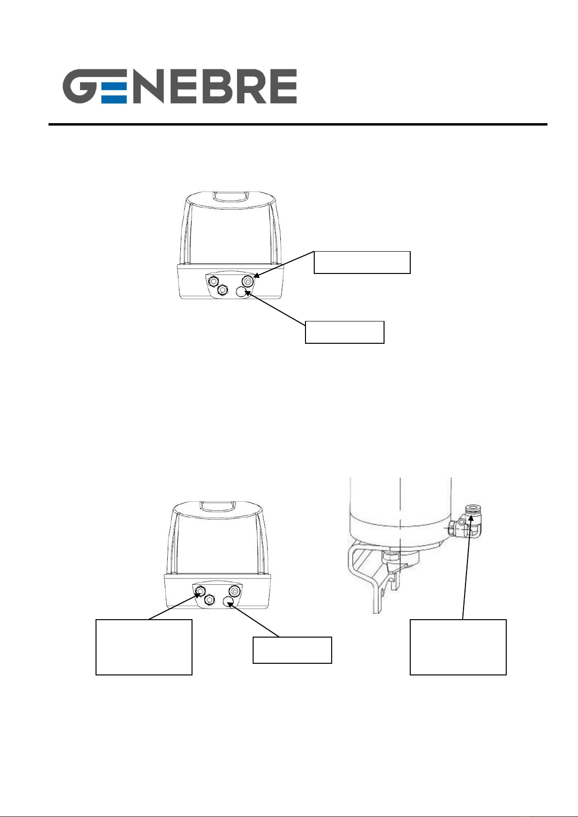
3.4) Pneumatic connection
All connectors for pneumatic installation are the "quick connector" kind, for a pipe Ø 6 mm.
Actuators with head come by default with all internal pneumatic connections installed
according to reference (5944 01 / 5944 02 / 5949 01 / 5949 02). It will only be necessary to
feed externally with air the corresponding connectors.
IMPORTANT: Power air has to be CLEAN and DRY.
Respect minimum and maximum power pressure (1,5 –6 bar)
Ref. 5949 01 (Simple actuator - 2 sensors –0 solenoid valves)
Air entrance
Muffler
Genebre Building. Av. de Joan Carles I, 46-48
08908 L'Hospitalet de Llobregat. Barcelona (Spain)
genebre@genebre.es - www.genebre.es
GENEBRE S.A.
LAST UPDATE: 01/07/2020 UPDATE NUMBER: 2
9
Ref. 5949 02 (Simple actuator - 2 sensors –1 solenoid valve)
Ref. 5949 01 (Double actuator - 2 sensors –0 solenoid valves)
Muffler
Air entrance
Power air
entrance
to open
Muffler
Power air
entrance
to close
Genebre Building. Av. de Joan Carles I, 46-48
08908 L'Hospitalet de Llobregat. Barcelona (Spain)
genebre@genebre.es - www.genebre.es
GENEBRE S.A.
LAST UPDATE: 01/07/2020 UPDATE NUMBER: 2
10
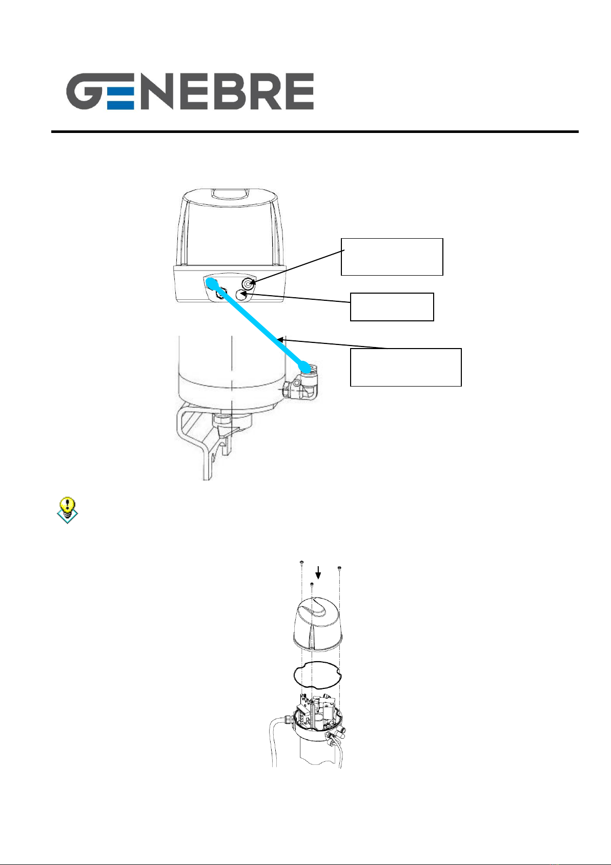
Ref. 5949 02 (Double actuator - 2 sensors –2 solenoid valves)
After installation, ALWAYS put back the cover to protect internal electrical components,
making sure the joint that keeps together cover and base is correctly placed. Avoid spilling
water inside the head.
.
Power air
entrance
Muffler
External
connection
This manual suits for next models
5
Table of contents
Other Genebre Switch manuals


