Genelec 1030A User manual

Genelec 1030A
Monitoring Speaker
Operating
Manual
1. General description1. General description
1. General description1. General description
1. General description
SystemSystem
SystemSystem
System
The bi-amplified GENELEC 1030A is a
two way active monitoring speaker
designed to be small but still have high
output, low coloration and broad
bandwidth. It shares many design
features with the famous 1031A near
field monitor.
Due to its compact size, integrated
construction, excellent dispersion and
precise stereo imaging, this speaker
system is ideal for Near Field
monitoring, mobile vans, broadcast and
TV control rooms, surround sound
systems and budget and home studios.
Designed as an active speaker, this
unit contains drivers, power amplifiers,
active crossover filters and protection
circuitry. The Directivity Control
Waveguide (DCW) technology used
provides excellent frequency balance
even in difficult acoustic environments.
DriversDrivers
DriversDrivers
Drivers
The bass frequencies are reproduced
by a 170 mm (6 1/2") bass driver loaded
in a 6.5 liter vented cabinet. The -3 dB
point lies at 52 Hz and the frequency
response extends down to 47 Hz
(-6 dB).
The high frequency driver is a 19 mm
(3/4") metal dome. Uniform dispersion
control is achieved with the
revolutionary DCW Technology
pioneered by Genelec, which has also
resulted in perfect phase and delay
uniformity at the crossover frequency.
Both drivers are magnetically shielded.
CrossoverCrossover
CrossoverCrossover
Crossover
The active crossover network consists
of two parallel bandpass filters.
Acoustically, the filters are
complementary and the slopes are
24 - 32 dB/octave. The crossover
frequency is 3.5 kHz. The active
crossover controls ('treble tilt', 'bass
tilt' and 'bass roll-off') allow this speaker
to be exactly matched to any
application.
AmplifiersAmplifiers
AmplifiersAmplifiers
Amplifiers
The amplifier unit is mounted to the
rear of the speaker enclosure on quick
release vibration isolators, to ensure
rattle free operation and long term
reliability. The bass and treble amplifier
produce 80 W and 50 W of short term
its required listening position, taking
note of the line of the listening axis (see
figure 2). Before connecting up, ensure
that the mains switch is off (see figure 4)
and the mains voltage selector is
correctly set. Audio input is via a
10 kOhm balanced XLR connector, but
unbalanced leads may be used as
long as pin 3 is grounded to pin 1 of the
XLR (see figure 3). Once the connection
has been made, the speakers are ready
to be switched on.
Setting the input sensitivitySetting the input sensitivity
Setting the input sensitivitySetting the input sensitivity
Setting the input sensitivity
The input sensitivity of the speakers
can be matched to the output of the
mixing desk, or other source, by
adjusting the input sensitivity control
on the rear panel (see figure 4). A small
screwdriver is needed for the
adjustment. The manufacturer's default
setting for this control is -6 dBu (fully
clockwise) which gives an SPL of
100 dB @1m with -6 dBu input level.
Setting tone controlsSetting tone controls
Setting tone controlsSetting tone controls
Setting tone controls
The response of the system may also
have to be adjusted to match the
acoustic environment. The adjustment
is done by setting the three tone control
switches 'treble tilt', 'bass tilt' and 'bass
roll-off' on the rear panel of the amplifier.
The manufacturer's settings for these
controls are 'All Off' to give a flat
anechoic response. See Figure 1 for
suggested tone control settings in
differing acoustic environments. Figure
5 shows the effect of the controls on the
anechoic response. Always start
adjustment by setting all switches to
'OFF' position. Then set only one switch
to the ON position to select the response
curve needed. If more than one switch
is set to 'ON' (within one switch group)
the attenuation value is not accurate.
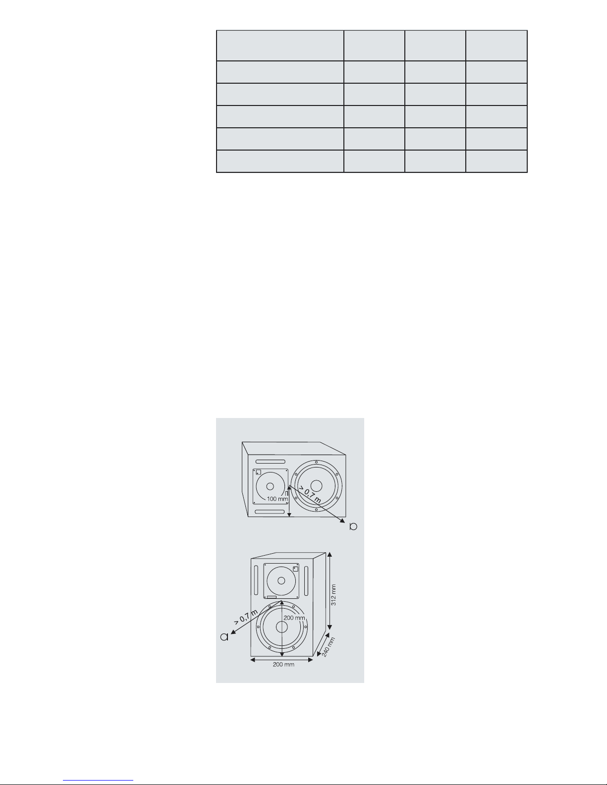
Figure 2. Speaker acoustic axis and
dimensions in horizontal and vertical
mounting positions.
power respectively. The fast, low
distortion amplifiers are capable of
driving a stereo pair to peak output
sound pressure levels in excess of 115
dB at 1 m. The unit incorporates special
circuitry for driver overload protection.
Variable input sensitivity allows for
accurate level matching to the mixing
console.
2. Installation2. Installation
2. Installation2. Installation
2. Installation
Each 1030A monitor is supplied with
an integrated amplifier unit, a mains
cable and an operating manual. After
unpacking, place the loudspeaker in
Figure 1. Suggested tone control settings for differing acoustic environments
noitisoPgnitnuoMrekaepS elberT
tliT
ssaB
tliT
ssaB
ffo-lloR
esnopserciohcenatalFenoNenoNenoN
moordepmadanignidnatseerFenoNBd2-enoN
moortnarebreveranignidnatseerFenoNBd4-Bd2-
egdirbelosnocnodleifraeNenoNBd4-enoN
renrocanIenoNBd4-Bd4-
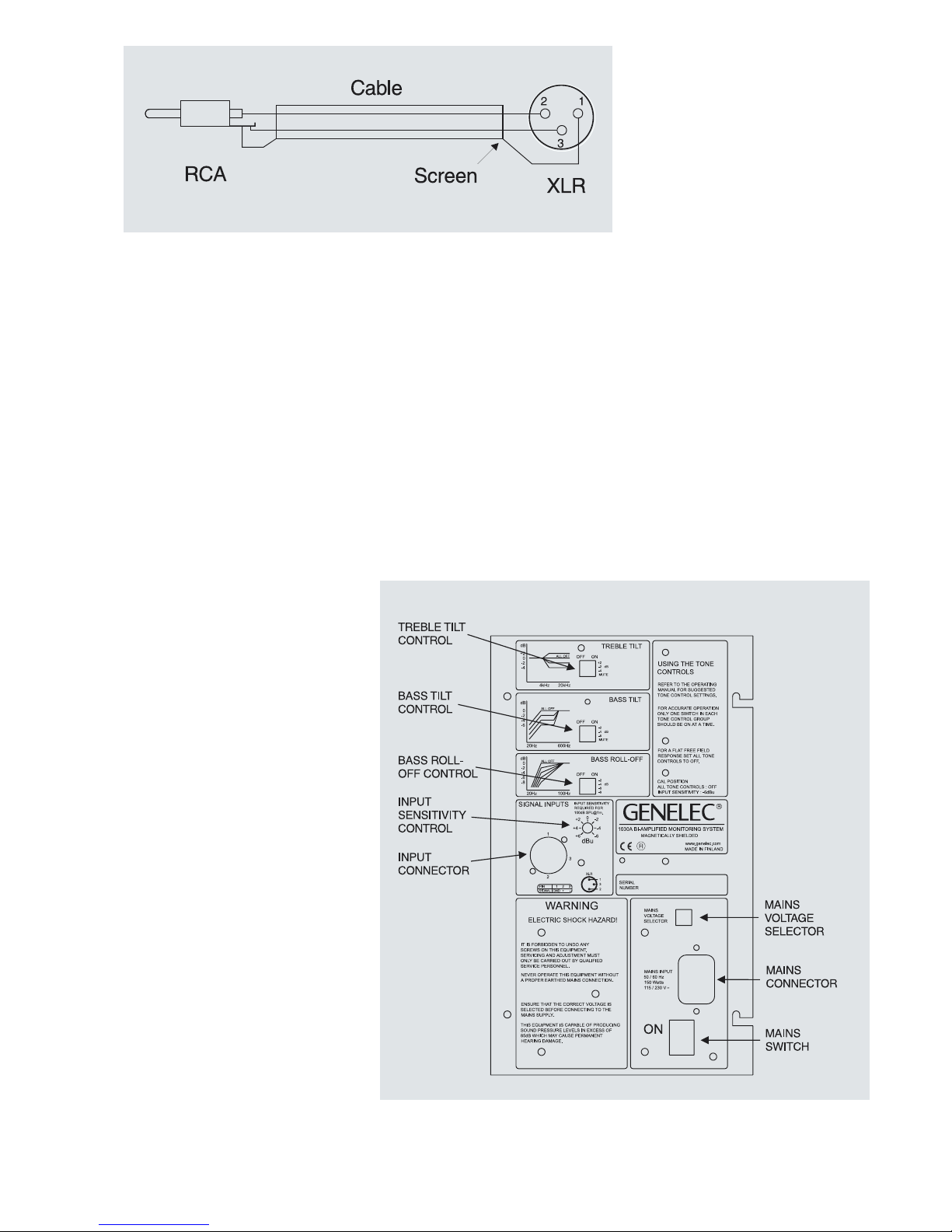
Figure 4. Rear panel layout.
Figure 3 . XLR connection if unbalanced input is required.
Vertical / horizontal mountingVertical / horizontal mounting
Vertical / horizontal mountingVertical / horizontal mounting
Vertical / horizontal mounting
The speakers are normally delivered
set up for vertical mounting. If horizontal
mounting is needed the DCW plate
may be rotated so that the GENELEC
logo is located at the bottom left corner
of the DCW. Remove the four corner
screws of the DCW (use a Torx 20
screw driver) and pull the plate carefully
out without stressing the wires or the
gasket. Rotate the plate 90 degrees in
the appropriate direction and remount
the screws. Note that to get a mirror
image pair, the DCWs must be rotated
in different directions for the left and
right speakers. When used in the
horizontal position, the bass drivers
should be on the inside to provide
better low frequency summing.
Console top mountingConsole top mounting
Console top mountingConsole top mounting
Console top mounting
If the 1030A's are used for console top
monitoring, avoid mounting the
speakers directly on the console.
Instead position the speakers slightly
behind the console by using floor
stands or wall mounts. This prevents
the reflection from the console surface
from coloring the sound.
3. Maintenance3. Maintenance
3. Maintenance3. Maintenance
3. Maintenance
No user serviceable parts are to be
found within the amplifier unit. Any
maintenance or repair of the 1030A
unit should only be undertaken by
qualified service personnel.
4. Safety Considerations4. Safety Considerations
4. Safety Considerations4. Safety Considerations
4. Safety Considerations
Although the 1030A has been designed
in accordance with international safety
standards, to ensure safe operation
and to maintain the instrument under
safe operating conditions, the following
warnings and cautions must be
observed:
•Servicing and adjustment must
only be performed by qualified service
personnel.
•The amplifier's rear panel must not
be opened, except by persons who
are aware of the hazards involved.
•Do not use this product with an
unearthed mains cable as this may
lead to personal injury.
WARNING!WARNING!
WARNING!WARNING!
WARNING!
This equipment is capable of producing
sound pressure levels in excess of
85 dB, which may cause permanent
hearing damage.
5. Accessories5. Accessories
5. Accessories5. Accessories
5. Accessories
Order code
Protective grille 1030-409
Wall mount 1030-404-V/H*
Floor stand 1030-405-V/H*
*State the desired speaker orientation
V=vertical or H=horizontal when
ordering these accessories.
6. Guarantee6. Guarantee
6. Guarantee6. Guarantee
6. Guarantee
This product is supplied with a one
year guarantee against manufacturing
faults or defects that might alter the
performance of the 1030A unit. Refer
to supplier for full sales and guarantee
terms.
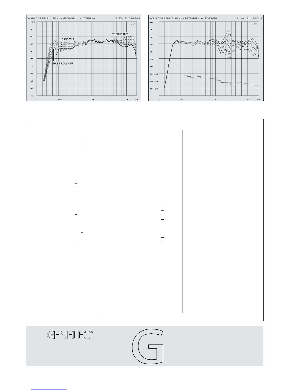
Figure 5. The curves above show the effect of the 'treble tilt', 'bass
tilt' and 'bass roll-off' controls on the free field response.
Figure 6. The upper curve group shows the horizontal directivity
characteristics of the 1030A measured at 1m. The lower curve is the
1/3 octave band power response.
SYSTEMSYSTEM
SYSTEMSYSTEM
SYSTEM
SPECIFICATIONSSPECIFICATIONS
SPECIFICATIONSSPECIFICATIONS
SPECIFICATIONS
AMPLIFIERAMPLIFIER
AMPLIFIERAMPLIFIER
AMPLIFIER
SECTIONSECTION
SECTIONSECTION
SECTION
Lower cut-off frequency, -3 dB: < 52 Hz
Upper cut-off frequency, -3 dB: > 20 kHz
Free field frequency response of system:
55 Hz - 18 kHz (± 2.5 dB)
Maximum short term sine wave acoustic
output on axis in half space, averaged from
100 Hz to 3 kHz:
@ 1m > 105 dB SPL
@ 0.5m > 111 dB SPL
Maximum long term RMS acoustic output in
same conditions with IEC weighted noise
(limited by driver unit protection circuit):
@ 1m > 99 dB SPL
@ 0.5m > 105 dB SPL
Maximum peak acoustic output per pair on
top of console, @ 1 m from the engineer
with music material: > 115 dB
Self generated noise level in
free field @ 1m on axis: < 10 dB
(A-weighted)
Harmonic distortion at 90 dB SPL @ 1m on
axis:
Freq: 60...150 Hz < 3%
> 150 Hz < 0.5%
Drivers: Bass 170 mm (6 1/2") cone
Treble 19 mm (3/4") metal
dome
Both drivers are magnetically shielded.
Weight: 7,6 kg (17 lb)
Dimensions:
Height 312 mm (12 1/4")
Width 200 mm ( 7 7/8")
Depth 240 mm (9 7/16")
Input connector: XLR female pin 1 gnd
pin 2 +
pin 3 -
Input impedance: 10 kOhm balanced
Input level for 100 dB SPL output @ 1m:
variable from +6 to -6 dBu
Input level for maximum short term sine
wave output of 105 dB SPL @ 1m:
variable from +11 to -1 dBu
Subsonic filter below 50 Hz :
18 dB/octave
Ultrasonic filter above 25 kHz:
12 dB/octave
Crossover frequency, Bass/Treble: 3.5 kHz
Crossover acoustical slopes:
24 - 32 dB/octave
Treble tilt control operating range in 2 dB
steps: from +2 to -4 dB &MUTE
Bass roll-off control operating range in 2 dB
steps: from 0 to -8 dB @ 50 Hz
Bass tilt control operating range in 2 dB
steps: from 0 to -6 dB @ 100 Hz
& MUTE
The 'CAL' position is with all tone controls
set to 'off' and the input sensitivity control to
maximum (fully clockwise).
CROSSOVERCROSSOVER
CROSSOVERCROSSOVER
CROSSOVER
SECTIONSECTION
SECTIONSECTION
SECTION
Bass amplifier output power with a 4 Ohm
load:
Short term 80 W
Treble amplifier output power with an
8 Ohm load:
Short term 50 W
Long term output power is limited by
driver unit protection circuitry.
Amplifier system distortion at
nominal output:
THD < 0.08%
SMPTE-IM < 0.08%
CCIF-IM < 0.08%
DIM 100 < 0.08%
Signal to Noise ratio, referred to full
output:
Bass > 95 dB
Treble > 95 dB
Mains voltage: 100/200 or 115/230 V
Voltage operating range: ±10%
Power consumption:
Idle 20 VA
Full output 100 VA
Genelec Oy, Olvitie 5
FIN - 74100 IISALMI, FINLAND
Phone: +358 - 17 - 83 881
Fax: +358 - 17 - 812 267
E-mail: [email protected]
Web: http://www.genelec.com
Note! All frequency response curves were measured in
a calibrated, 12 m cube, anechoic chamber at 1 m
using grade 1 measuring equipment. Input signal levels
were set at -20 dBu. The anechoic chamber error in the
free field response is less than 0.5 dB down to 60 Hz.
Data Sheet No. DR30001
COPYRIGHT GENELEC OY 6/1999
All data subject to change without prior notice
Genelec Inc, 7 Tech Circle
Natick, MA 01760, USA
Phone: +1 - 508/652-0900
Fax: +1 - 508/652-0909
E-mail: [email protected]
Other Genelec Speakers manuals

Genelec
Genelec SAM 8320A User manual

Genelec
Genelec 4410A User manual

Genelec
Genelec 1038A User manual

Genelec
Genelec 2029A User manual

Genelec
Genelec response controls User manual

Genelec
Genelec 6010A User manual

Genelec
Genelec 1034B User manual

Genelec
Genelec 8381A User manual

Genelec
Genelec G One User manual

Genelec
Genelec 4435A User manual

Genelec
Genelec 1034B User manual

Genelec
Genelec HT312B User manual

Genelec
Genelec SAM 1234AC User manual

Genelec
Genelec 4420A User manual

Genelec
Genelec 1038BC User manual

Genelec
Genelec 8020A User manual

Genelec
Genelec 1032A User manual

Genelec
Genelec 4020C User manual

Genelec
Genelec 1238AC User manual

Genelec
Genelec G Three User manual


