Introduction and Safety
Owner’s Manual for CTF10 Light Tower 1
Section 1: Introduction and Safety
Introduction
Thank you for purchasing a Generac Mobile Products LLC
product. This unit has been designed to provide high
performance, efficient operation, and years of use when
maintained properly.
The information in this manual is accurate based on prod-
ucts produced at the time of publication. The manufacturer
reserves the right to make technical updates, corrections,
and product revisions at any time without notice.
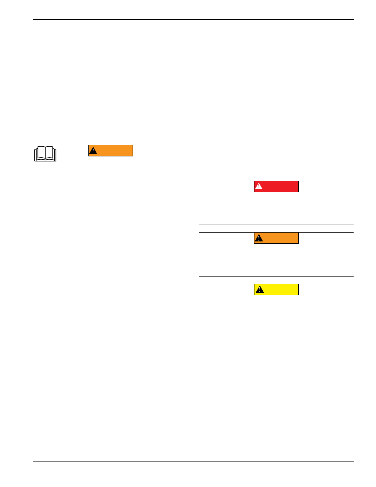
Read This Manual Thoroughly
(000100a)
WARNING
Consult Manual. Read and understand manual
completely before using product. Failure to
completely understand manual and product
could result in death or serious injury.
If any section of the manual is not understood, contact your
nearest Generac Mobile Products Authorized Service
Dealer, or contact
Generac Mobile Products LLC at 1-800-
926-9768, or
Generac Mobile Products Technical Service at
1-800-926-9768 or www.generacmobileproducts.com
with any questions or concerns.
The owner is responsible for proper maintenance and safe
use of the equipment. Comply with regulations the
Occupational Safety and Health Administration (OSHA)
has established, or with equivalent standards. Also, verify
that the unit is applied, used, and maintained in accordance
with the manufacturer's instructions and recommendations.
Do nothing that might alter safe application/usage and
render the unit in noncompliance with the aforementioned
codes, standards, laws, and regulations
.
Save these instructions for future reference. This manual
contains important instructions for the unit that should be
followed during setup, operation and maintenance of the
unit and battery. ALWAYS supply this manual to any
individual that will use this machine.
How to Obtain Service
W
hen the unit requires servicing or repairs, contact a
Generac Mobile Products Authorized Service Dealer (GMP
ASD) for assistance. Service technicians are factory-trained
and are capable of handling all service needs. For
assistance locating a dealer, visit
www.generacmobileproducts.com/parts-service/find-
service.
When contacting a GMP ASD about parts and
service, always supply the complete model number and
serial number of the unit as given on its data decal located
on the unit. Record the model number and serial numbers
in the spaces provided on the inside front cover of this
manual.
Safety Rules
The manufacturer cannot anticipate every possible
circumstance that might involve a hazard. The warnings in
this manual, and on tags and decals affixed to the unit are,
therefore, not all inclusive. If using a procedure, work
method or operating technique that the manufacturer does
not specifically recommend, verify that it is safe for others.
Also make sure the procedure, work method or operating
technique utilized does not render the equipment unsafe.
Throughout this publication, and on tags and decals affixed
to the unit, DANGER, WARNING, CAUTION and NOTE
blocks are used to alert personnel to special instructions
about a particular operation that may be hazardous if
performed incorrectly or carelessly. Observe them
carefully. Their definitions are as follows:
(000001)
DANGER
Indicates a hazardous situation which, if not avoided,
will result in death or serious injury.
(000002)
WARNING
Indicates a hazardous situation which, if not avoided,
could result in death or serious injury.
(000003)
CAUTION
Indicates a hazardous situation which, if not avoided,
could result in minor or moderate injury.
NOTE: Notes contain additional information important to
a procedure and will be found within the regular text of
this manual.
These safety alerts cannot eliminate the hazards that they
indicate. Common sense and strict compliance with the
special instructions while performing the action or service
are essential to preventing accidents.