General Equipment RIP-R-STRIPPER CTS12GEN2 User manual

OPERATOR’S MANUAL
Safety, Operation & Service Information
RIP-R-STRIPPER®Floor Covering Stripper
Model: CTS12GEN2
Form: GOM11121101US, Version 1.2, Original Instructions
•Do not discard this manual.
•Keep manual readily available for reference during operation or when servicing product.
•Before operation, read and comprehend operator manual content.
•Customer Service: 001 507 451 5510
•Customer Service Telefax: 001 507 451 5511
Note: There is no charge for Customer Service.
•Internet Address: http://www.generalequip.com
•Email: general@generalequip.com
•Mailing Address:
General Equipment Company, 620 Alexander Dr. S.W., P.O. Box 334, Owatonna, MN 55060, USA
EUROPEAN REPERESENTATIVE
•Customer Service: (+31) 5 23 63 82 86
•Internet Address: http://www.eurogate-international.com
•Email: info@eurogate-international.com
•Mailing Address: Eurogate International, Galilieistraat 6, 7701 SK Dedemsvaart, The Netherlands
Product covered by this manual complies with mandatory requirements of 2006/42/EC.
Copyright 2021, General Equipment Company, All rights reserved.

CTS12GEN2 RIP-R-STRIPPER®FLOOR COVERING STRIPPER
FORM GOM11121101US, VERSION 1.2
English-EN 1
TABLE OF CONTENTS
1 INTRODUCTION ……………………….…………… 3
2 INTENDED USE …………………….….…………… 3
3 TRAINING ……………………………….…………… 3
4SAFETY SYMBOLS………………………..……….. 3
5SAFETY INSTRUCTIONS ………….……………… 3
6MACHINE SPECIFICATIONS ………….………….. 7
7STANDARD PRODUCT & ACCESSORIES ……... 7
8MACHINE SET-UP .……………………….………… 8
9APPLICATION THEORY & TECHNIQUES ………. 11
10 OPERATING INSTRUCTIONS ………….…………. 12
11 MAINTENANCE INSTRUCTIONS ………………… 15
12 SERVICE/REPAIR INSTRUCTIONS ……………… 16
13 TROUBLESHOOTING ……………………………… 17
14 STORAGE ……………………………………………. 18
15 END OF LIFECYCLE ……………………………….. 18
16 DECLARATION OF CONFORMITY ………………. 18
17 REPLACEMENT PARTS …………………………....20
NOTICE TO OPERATORS
IF YOU CAN NOT READ OR DO NOT FULLY UNDERSTAND THE
CONTENTS OF THIS MANUAL, PLEASE CONTACT THE FACTORY FOR
PROPER ASSISTANCE BEFORE ATTEMPTING TO OPERATE THIS
PRODUCT.
SI TU NO PUEDES LE’ER O NO COMPRENDES EL CONTENIDO DE ESTE
MANUAL FAVOR DE PONERSE EN CONTACTO CON LA. FABRICA PARA
ASSISTENCIA-APROPIA ANTES DE INTENTAR PARA OPERAR ESTE
PRODUCTO.
SOLLTEN SIE DIESE GEBRAUCHSANWEISUNG NICHT LESEN KOENNEN
ODER ES NICHT VOLLKOMMEN VERSTEHEN, WENDEN SIE SICH BITTE
AN DEN HERSTELLER FUER RICHTIGE HILFE EHE SIE VERSUCHEN
DIESES PRODUKT ZU OPERIEREN.
SI VOUS NE LISEZ OU NE COMPRENDRE ENTIEREMENT LES MATIERES
DE CE MANUEL, S’IL VOUS PLAIT, CONTACTEZ L’USINE POUR
L’ASSISTANCE APPROPRIEE AVANT D’UTILISER LE PRODUIT.
IMPORTANT:
•DO NOT allow anyone to operate RIP-R-STRIPPER without first reading
this Operator Manual and becoming familiar with RIP-R-STRIPPER
operation.
•Manufacturer of this RIP-R-STRIPPER has gone to great extremes to
provide owner(s) and/or operator(s) with the finest equipment available
for its intended job function of removing covering materials from concrete
and wood floor surfaces. Yet, the possibility exists RIP-R-STRIPPER can
be utilized in and/or subjected to job applications not perceived and/or
anticipated by manufacturer. Such misuse and/or misapplication of
RIP-R-STRIPPER can lead to possibility of serious damage, injury or
even death.
•It is responsibility of owner(s) and/or operator(s) to determine
RIP-R-STRIPPER is utilized and/or operated within scope of its intended
job function.
•It is responsibility of owner(s) and/or operator(s) to establish, monitor and
constantly upgrade all safety programs and/or practices utilized in and for
operation of RIP-R-STRIPPER. Purpose of such programs is to provide
for owner(s') and/or operator(s') safety. Operators must be instructed to
recognize and avoid unsafe conditions associated with their work (29
CFR 1926.21 (b)(2)) and/or applicable updated revisions.
•It is responsibility of owner(s) and/or operator(s) to determine no
modifications and/or alterations have been made to RIP-R-STRIPPER.
Modifications and/or alterations can lead to possibility of serious damage,
injury or even death. It is responsibility of owner(s) and/or operator(s) to
make this Operator Manual available for consultation during all phases of
operation.
•Refer to OSHA 2207 and/or applicable updated revisions which contains
all OSHA job safety, health rules and regulations (1926 and 1910)
covering construction.
CAUTION
The concept of electrically powered, walk-behind floor covering removal
equipment has been successfully utilized for many years as a practical solution
to many types of floor covering removal requirements. The basic concept is
proven and well accepted within the associated marketplaces.
Use of a RIP-R-STRIPPER requires strenuous work activity. This type of work
activity can be considered to be greater in magnitude than that experienced
with the use of many other types of both light construction and lawn and garden
related equipment. This type of work activity should only be attempted by
operators of adequate physical size and stature, mental awareness, and
physical strength and condition.
The body parts most noticeably affected during the floor covering removal
process are the arms, hands, wrists, shoulders, lower back and legs. The
covering removal process can also produce excessive stress/strain directly to
the back muscles, spinal vertebrae and many other body parts. Back and wrist
related pain can be side effects of using the RIP-R-STRIPPER. Use of
RIP-R-STRIPPER may only aggravate this and any other medically related
problem.
Because of the diverse type of prevailing floor removal conditions, operator
experience levels and operator physical characteristics, no warranty,
guarantee, representation and/or liability is made by the manufacturer as to the
absolute correctness or sufficiency of any operational procedure, operational
position and/or technique. There is no absolute guarantee that an operator of
any given experience level, physical size and/or physical condition will be
immune to the possibility of and/or probable physical side effects of the normal
use of the RIP-R-STRIPPER.
Each potential operator of the RIP-R-STRIPPER must be made aware of and
assume the operational and physical liability described and/or associated with
the use of the RIP-R-STRIPPER. Each potential operator not willing to
assume the operational and physical liability described and/or associated
with the use of the RIP-R-STRIPPER should not operate it.Proper levels of
operator experience, skill and common sense are essential for maximizing the
safe and efficient operation of the RIP-R-STRIPPER.
Record RIP-R-STRIPPER and electric motor serial numbers in spaces
provided below.
Model Number: __________________________________________________
Serial Number: __________________________________________________
Electric Motor Serial Number: _________________________________
Date of Purchase: ________________________________________________
Specifications and design are subject to change without notice or obligation. All
specifications are general in nature and are not intended for specific application
purposes. General Equipment Company reserves the right to make changes in
design, engineering or specifications and to add improvements or discontinue
manufacture at any time without notice or obligation. General Equipment
Company and its agents accept no responsibility for variations which may be
evident in actual products, specifications, pictures and descriptions contained in
this publication.

CTS12GEN2 RIP-R-STRIPPER®FLOOR COVERING STRIPPER
FORM GOM11121101US, VERSION 1.2
English-EN 2
OPERATOR INSTRUCTIONAL DATA SHEET
The following undersigned operators of RIP-R-STRIPPER described and/or pertaining to this Operator Manual have received formal safety and operational
information/instruction from undersigned owner(s)/instructor(s) in accordance to OSHA 29 CFR 1926.21 (b)(2) and/or applicable updated revisions pertaining to,
but not necessarily limited to the:
1. READING, COMPREHENSION AND ACKNOWLEDGEMENT OF MATERIAL COMPRISING ENTIRE CONTENTS OF APPLICABLE OPERATOR
MANUAL FOR RIP-R-STRIPPER.
2. FORMALIZED OPERATOR SAFETY PROGRAM TO BE DEVISED BY OWNER OF RIP-R-STRIPPER IN CONJUNCTION WITH CONTENTS OF
APPLICABLE OPERATOR MANUAL FOR RIP-R-STRIPPER.
3. OSHA RULES AND REGULATIONS RESEARCHED FOR AND/OR BY OWNER OF RIP-R-STRIPPER AND DEEMED APPLICABLE TO SAFE AND
PROPER USE AND/OR OPERATION OF RIP-R-STRIPPER FOR ANY SPECIFIC JOB APPLICATION.
4. LOCAL LAWS, REGULATIONS AND CUSTOMS RESEARCHED FOR AND/OR BY OWNER OF RIP-R-STRIPPER AND DEEMED APPLICABLE TO
SAFE AND PROPER USE AND/OR OPERATION OF RIP-R-STRIPPER FOR ANY SPECIFIC JOB APPLICATION.
5. FORMALIZED MAINTENANCE PROGRAM FOR RIP-R-STRIPPER TO BE DEVISED BY OWNER OF RIP-R-STRIPPER IN ACCORDANCE WITH, BUT
NOT NECESSARILY LIMITED TO, SPECIFICATIONS, GUIDELINES AND OPERATIONAL INFORMATION CONTAINED IN APPLICABLE OPERATOR
MANUAL.
6. COMPREHENSIVE OPERATIONAL INSTRUCTIONS FOR CORRECT AND PROPER USE OF RIP-R-STRIPPER AS PER CONTENTS OF
APPLICABLE OPERATOR MANUAL.
_________________________________ Operator ______________________________ Owner/Instructor __________ Date
NOTE: INSERT COPIES OF THIS PAGE WITHIN OPERATOR’S MANUAL IF SPACE FOR ADDITIONAL OPERATORS IS REQUIRED.

CTS12GEN2 RIP-R-STRIPPER®FLOOR COVERING STRIPPER
FORM GOM11121101US, VERSION 1.2
English-EN 3
1 INTRODUCTION
Congratulations on your decision to purchase a General Equipment light
construction product. From our humble beginnings in 1955, it has been a
continuing objective of General Equipment Company to manufacture
equipment that delivers uncompromising value, service life and investment
return. Because of this continuous commitment for excellence, many products
bearing the General name actually set the standard by which competitive
products are judged.
When you purchased this product, you also gained access to a team of
dedicated, knowledgeable, support personnel that stand willing and ready to
provide field support assistance. Our team of sales representatives and in-
house factory personnel are available to ensure each General product delivers
the intended performance and product safety you expect. Our personnel can
readily answer your questions or concerns regarding proper applications,
service requirements and warranty related problems.
If you have any questions or concerns about this product, please feel free to
contact our Customer Service Department during normal business hours using
the contact information located on the front cover of this manual. There is no
charge for this service.
Sincerely,
The General Equipment Team
2 INTENDED USE
The RIP-R-STRIPPER is intended for use in removing ceramic tile, hardwood
flooring and other similar materials from cement surfaces in a nonexplosive
atmosphere. The machine is operated by one adult of proper operator
experience/skill/common sense, height, weight, strength and physical condition.
Minors should never be allowed to operate the RIP-R-STRIPPER.
RIP-R-STRIPPER is classified as a low cost, push style, low power, portable
type machine. The number of practical and/or suitable job applications for this
type machine is limited. A particular job application variables and operator
experience/skill/common sense may require a different type machine, method,
and/or process to properly complete job efficiently and safely. Contact
Customer Service Department for specific information regarding suitable job
applications, job sites, flooring conditions and operator experience/skill/
common sense recommendations for RIP-R-STRIPPER BEFORE utilization.
Never exceed the recommended capacities of the RIP-R-STRIPPER. Refer to
BEFORE OPERATING and SPECIFICATIONS sections in this manual for
more detailed information. Always utilize correct chisels, blades and extension
cord designed for use with the RIP-R-STRIPPER. Use of an incorrect chisel,
blade or extension cord can result in property damage and/or personal injury.
3 TRAINING
Develop a comprehensive program for safe RIP-R-STRIPPER operation by
owner(s) and/or operator(s). Program will include, but is not limited to:
instructional operation requirements, applicable OSHA requirements, local
laws and regulations, job site safety plus RIP-R-STRIPPER maintenance.
Constantly examine and upgrade program to guarantee owner(s’) and/or
operator(s) safety. Each operator must be fully instructed regarding specifics of
this safety program.
4 SAFETY SYMBOLS
SAFETY ALERT SYMBOL & SIGNAL WORDS
The safety alert ‘general warning” symbol indicates a potential personal injury
hazard. A signal word (DANGER, WARNING, or CAUTION) is used with the
alert symbol to designate the degree or level of hazard seriousness. Other
safety sumbols may be used to represent the type of hazard in combination
with “general warning” symbol, in highlighted boxes, or individually.
DANGER:
Indicates a hazard with a high level of risk which, if not voided, will result in
death or serious injury.
WARNING:
Indicates a hazard with a medium level of risk which, if not avoided, could result
in death or serious injury.
CAUTION:
Indicates a hazard with a low level of risk which, if not avoided, could result in
minor or moderate injury.
The following safety alert symbols identify important safety messages in this
manual. When you see these symbols, be alert to the possibility of personal
injury and carefully read the message that follows.
HAZARD SYMBOLS & MEANINGS
Symbol
Meaning
Symbol
Meaning
Action
Required
No Trash
Containers
Read Manual
General Warning
Wear Ear
Protection
Warning,
Flammable
Material
Wear Eye
Protection
Warning,
Explosive
Material
Wear
Protective
Gloves
Warning, Toxic
Material
Wear Safety
Shoes
Warning,
Electricity
Wear Breathing
Protection
Warning, Body
Entrapment
Disconnect
From Power
Warning, Sharp
Element
No Open
Flame
Warning, Floor
Level Obstacle
No Smoking
Warning, Drop
Off
No Active
Mobile Phone
Warning, Slippery
Surface
No Food Or
Drink
5 SAFETY INSTRUCTIONS
NOTE: For SDS (Safety Data Sheets) pertaining to materials such as oil,
lubricants and/or solvents used in conjunction with RIP-R-STRIPPER, visit the
LIBRARY section of our website at www.generalequip.com .
OPERATIONAL DISCLAIMER
The manufacturer of this RIP-R-STRIPPER makes no warranty or
guarantee it is merchantable and/or suitable for a specific job application
and that it will have the power required to dig a specific diameter hole
down to a specific depth in a specific soil classification.
WARNING
•These safety instructions provide guidelines to promote safety
and efficiency with the RIP-R-STRIPPER.
•No warranty, guarantee or representation is made by
manufacturer as to absolute correctness or sufficiency of any
information or statement.
•Safety instructions are intended to deal with common practices
and conditions encountered in the use of RIP-R-STRIPPER and
are not intended to be all inclusive.
•Not following instructions in this manual can result in property
damage, personal injury and/or death.
DANGER
•This product can expose you to chemicals including
greases, lubrication oils, silica dusts and asbestos which
are known to the State of California to cause cancer and
carbon monoxide (if gas powered) which can cause birth
defects or other reproductive harm. For more
information: www.P65Warnings.ca.gov. .

CTS12GEN2 RIP-R-STRIPPER®FLOOR COVERING STRIPPER
FORM GOM11121101US, VERSION 1.2
English-EN 4
BEFORE OPERATING
1. BEFORE operating RIP-R-STRIPPER, read this manual plus applicable
safety/operational information supplied by electric breaker manufacturer
to familiarize each operator with correct operating procedures.
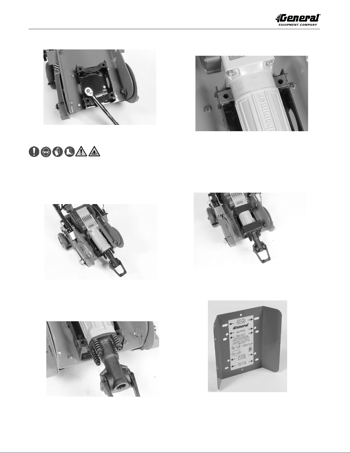
2. Visually inspect RIP-R-STRIPPER per MAINTENANCE INSTRUCTIONS
STEPS 5 through 12 of this manual.
3. Determine RIP-R-STRIPPER is in original, factory configuration and has
not been modified in any manner. If questions arise about possible
modifications, contact the Customer Service Department BEFORE
utilization. There is no charge for this service.
4. Always start and stop RIP-R-STRIPPER according to instructions to
minimize possibility of unexpected or uncontrolled chisel/blade
movement. Know how stop unit in an emergency.
Physical Exertion/Body Strain
Operating RIP-R-STRIPPER requires proper physical stamina, mental
alertness and is strenuous. Operators must be in proper physical condition,
mental health and not under the influence of any substance (drugs, alcohol,
etc.) which might impair vision, dexterity or judgment. Take work breaks to
maintain stamina and alertness. If you have condition(s) that might be
aggravated by strenuous work, check with doctor BEFORE operating.
Vibration
Prolonged use of RIP-R-STRIPPER (or other, similar machines) exposes
operator to vibrations which may produce Whitefinger Disease (Raynaud's
Phenomenon) reducing hand's ability to feel and regulate temperature, produce
numbness and burning sensations and may cause nerve, circulation damage
and tissue necrosis. Continuous and regular users should closely monitor
condition of hands and fingers. After each period of use, exercise to restore
normal blood circulation. If any symptoms appear, seek medical advice
immediately.
Noise
Electric breaker mounted to RIP-R-STRIPPER and actual floor covering
removal process creates exposure to high noise emission levels that can result
in hearing loss or damage. Hearing protection is required while operating or
when near operating equipment. Continuous and regular operators should have
hearing checked regularly.
Clothing
Clothing must be sturdy, snug fitting, but allow complete freedom of movement.
Never wear loose fitting jackets, scarves, neckties, jewelry, flared or cuffed
pants or anything that could become caught on controls or moving parts.
Properly secure eyeglasses, hearing aid devices and other medical related
devices. Wear long pants to protect legs. Protect hands and improve grip with
heavy duty, nonslip gloves. Wear and properly lace sturdy boots with nonslip
soles. Steel-toed safety shoes are mandatory. Wear approved safety hard hat
where there is danger of head injuries and/or approved breathing mask where
danger of airborne particulate contamination is present.
Flying Debris
Floor covering removal process can result in flying debris. Eye protection and
appropriate safety apparel is required when near or operating RIP-R-
STRIPPER. DO NOT operate unit with onlookers or animals close by.
BACK CARE & PROPER LIFTING PROCEDURES
Operators will be required to lift RIP-R-STRIPPER, as demanded by specific
job applications. When lifting, two people are required. Utilize proper lifting
techniques to minimize fatigue and back-related injuries.
Back Anatomy
The human body is supported by the spinal column consisting of thirty bones
called vertebrae, all linked and supported by a series of tiny muscles. Pads
called discs separate each vertebrae, acting as cushions to pressure from
external forces. Spinal column is wrapped by nerve system with three sections
that require being kept in natural alignment to prevent discomfort:
Cervical: From base of neck to the brain.
Thoracic: From middle to lower back.
Lumbar: From lower back to buttocks area.
BACK CARE PREVENTATIVE MEASURES
Most occupational physicians agree on several “universal” preventative
measures an operator should follow to help lower risk of back-related injuries:
1. Maintain proper body weight.
2. Eliminate/reduce use of tobacco. Smoking reduces oxygen supply and
nutrients to discs cushioning vertebrae.
3. Develop a consistent exercise routine.
4. Maintain good posture while walking or sitting.
5. Watch how you twist/bend your body. Twisting/bending incorrectly can
exert too much pressure on one side of your vertebrae.
6. Use firm footing, keep intended path clear before carrying RIP-R-
STRIPPER.
7. Always use proper lifting techniques as described below.
PROPER LIFTING PROCEDURES
The following are guidelines for properly lifting RIP-R-STRIPPER are not
intended to be all inclusive. Plan your path and make sure there are no
obstructions or tripping hazards. Consider how you will set the load. The spinal
column is a very sensitive mechanism. At any given time, improper lifting
procedures can cause damage that can lead to injury.
1. Position your feet a comfortable distance (shoulder width) apart to help
provide necessary balance.
2. Tighten stomach muscles by pulling in your stomach. Keep your back as
straight as possible to keep spine, back muscles/igaments in alignment.
3. Bend at hips and knees as much as possible.
4. Start lifting RIP-R-STRIPPER by thrusting feet while lifting as much as
possible with your leg muscles. Use smooth movements.
5. Once RIP-R-STRIPPER is lifted, keep it close as possible to the body.
Avoid turning at the waist. To turn, pivot your entire body.
6. Keep your shoulders, hips and feet pointed in same direction.
IMPORTANT: Use firm footing, keep intended path clear before carrying
RIP-R-STRIPPER.
TRANSPORTATION
1. When transporting RIP-R-STRIPPER, remove extension cord and store.
Remove accessory tool from electric breaker according to INSTALLING &
REMOVING ACCESSORY TOOLS in MACHINE SET-UP section of this
manual when in following operating conditions:
a) To and from jobsite.
b) Longer distances while being repositioned on jobsite.
c) Traversing up and down stairways.
d) Performing maintenance and/or repairs.
e) Lifting/lowering from transportation vehicle.
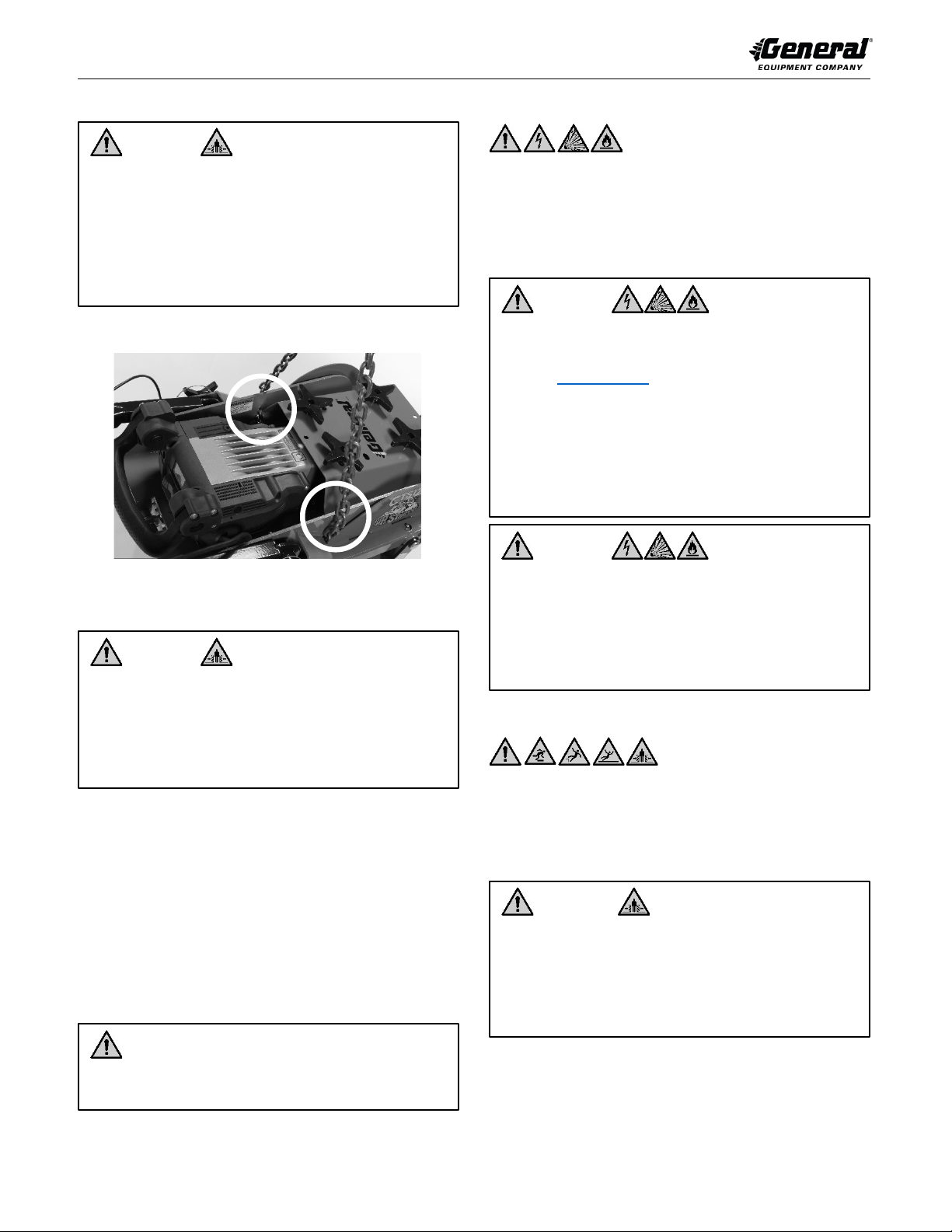
DANGER
•Lifting/lowering and transporting RIP-R-STRIPPER with
accessory tool installed and/or improperly secured can
result in property damage and/or personal injury.
DANGER
•Disconnect extension cord from RIP-R-STRIPPER when
traversing up and down stairs.
•Improperly stored/connected cord can entrap and/or
entangle personnel.
•Such occurrence can result in property damage and/or
personal injury.

CTS12GEN2 RIP-R-STRIPPER®FLOOR COVERING STRIPPER
FORM GOM11121101US, VERSION 1.2
English-EN 5
2. To use two people to lift/lower machine, grip both sides of operator
handles and breaker tool receiver.
3. Use mechanical device to lift/lower machine. Attach chain and suitable
attachment device to lifting bail area on upper frame side. FIGURE 1
FIGURE 1
NOTE: This location may not always be the exact center of gravity for the
machine.
4. To reduce storage area and minimize damage, transport
RIP-R-STRIPPER in normal upright position with operator handle folded
relative to main frame. Refer to MACHINE SET-UP section of this
manual.
a) DO NOT allow operator handle and main frame to make direct
contact with each other while transporting. Provide proper
protection between RIP-R-STRIPPER components and
vehicle.
b) DO NOT drop unit directly against breaker tool receiver or
wheels to prevent damage to machine and/or breaker.
5. All equipment must be secured in/on vehicles with suitable strapping or
tie downs. Personnel should not be transported in same compartment as
equipment and supplies. Consult applicable OSHA regulations for specific
information.
DETERMINATION OF POTENTIAL SUBSURFACE HAZARDS IN
PROPOSED FLOORING REMOVAL LOCATION(S)
RIP-R-STRIPPER operator handle grips are constructed of non-metallic,
composite material and do not guarantee operators will be properly insulated
from contact with charged electrical cables. RIP-R-STRIPPER and related
accessories are not classified as insulated.
RIP-R-STRIPPER is not sealed or insulated. DO NOT operate
RIP-R-STRIPPER in an explosive atmosphere or near combustible materials.
Refer to OSHA rules and regulations.
DETERMINATION OF POTENTIAL ABOVE SURFACE HAZARDS IN
PROPOSED FLOORING REMOVAL LOCATION(S)
Normal RIP-R-STRIPPER use is on level surfaces. Avoid other surface
conditions which can be dangerous. Special care must be exercised on slippery
and/or difficult/uneven surfaces. Watch for cracks, high spots/other surface
irregularities or drop offs to lower floor levels. Operate only when/where
visibility and light are adequate for the job at hand. Remove any trip/fall hazard
BEFORE operating RIP-R-STRIPPER. Keep proper footing and balance at all
times.
DANGER
•DO NOT attempt carrying/lifting/lowering RIP-R-
STRIPPER into/from transportation vehicle using only
one person.
•Use two people or appropriate capacity power tailgate
unit or hoist for such applications.
•Personnel not in proper physical/mental condition or
unfamiliar in operation of lifting devices should not
attempt such procedures.
•Such actions can result in property damage and/or
personal injury.
DANGER
•Exercise extreme caution using mechanical lit devices.
•Use mechanical lift devices in accordance with their
static and dynamic design envelope.
•DO NOT use mechanical lift devices until lift device
operation/application guidelines are properly known and
understood by all applicable personnel.
•Failure to properly use mechanical lifting device can
result in property damage and/or personal injury.
CAUTION
•An improperly secured RIP-R-STRIPPER and related
accessories can fall from moving vehicle and result in property
damage and/or personal injury.
DANGER
•Always assume floor covering removal location contains
buried underground obstructions.
•BEFORE attempting to operate RIP-R-STRIPPER in
proposed location(s), call 811 and/or visit
www.Call811.com .
•Contact all appropriate agencies to determine exact
location(s) of all buried pipelines, powerlines and material
debris.
•Many utilities and other agencies will perform these tasks
at minimal charge or at no cost. Have all subsurface
hazards marked for easy recognition.
•Direct contact with these and other subsurface hazards
can result in property damage and/or personal injury
through such things as electrocution and/or explosion.
DANGER
BEFORE attempting to operate RIP-R-STRIPPER, identify/mark all
potential subsurface hazards in proposed floor covering removal
location(s). Potential subsurface hazards may include, but may not
be limited to the following:
1. Buried debris, rotted timbers or wood planking.
2. Buried pressurized pipelines (e.g. natural gas, propane,
etc.)
3. Buried electrical cables.
WARNING
•DO NOT operate RIP-R-STRIPPER on jobsite location
where forces generated during floor covering removal
process can allow body parts to come in direct contact
with vertical wall, foundation or other support type
structures in close proximity.
•Such occurrence can result in property damage and/or
personal injury. Always maintain a safe and reasonable
distance from these type structures.

CTS12GEN2 RIP-R-STRIPPER®FLOOR COVERING STRIPPER
FORM GOM11121101US, VERSION 1.2
English-EN 6
OPERATIONAL HAZARDS
1. RIP-R-STRIPPER is designed to substantially enhance machine control
and reduce operator fatigue provided accessory tool does not directly
contact larger, protruding obstructions (anchor bolts, pipes, nail heads,
columns, openings, large cracks, utility outlets, material variances, etc., or
any objects protruding from work surface). Such contact can result in
rapid and jerky movement of machine and loss of machine control.
2. The floor covering material removal process can produce sparks, dusts
and other foreign particle contamination that can result in fire and/or
explosion depending on existing jobsite conditions.
3. Many covering materials, adhesives or mastics can contain asbestos and
other chemicals that are known to cause physical harm and/or affect the
environment.
4. Excessive water, and/or other conductive materials on work surface can
result in electrocution of operator and/or other personnel.
Preventive Measures:
•Operator must maintain physical and mental alertness. Be prepared for
unexpected accessory tool contact with protruding anchor bolts, etc. and
be capable to sense level of machine control they have.
•DO NOT operate RIP-R-STRIPPER on jobsite where kickback forces can
allow body parts to come in direct contact with vertical wall, foundation or
other support type structures. Maintain a safe and reasonable distance
from these structures.
•Maintain proper operating stance for better control of machine plus,
reducing operator error and fatigue. Refer to OPERATOR STANCES in
OPERATING INSTRUCTIONS section of this manual for more
information.
•Remove water and/or conductive materials by industry-approved and/or
accepted practice BEFORE removing floor covering. Determine RIP-R-
STRIPPER is properly grounded and extension cords are free of cuts,
abrasions and/or exposed cable strands.
•Dust and other particle contamination can be controlled by use of
appropriate industrial-type dust collection system to remove/control dust
and other particle contamination from work surface.
CAUTION
•Exercise extreme caution when operating RIP-R-STRIPPER
in vicinity of anchor bolts, pipes, columns, openings, large
cracks, utility outlets or any other object protruding from work
surface.
•Contact with such objects can lead to loss of machine control,
resulting in property damage and or personal injury.
WARNING
•Exercise extreme caution when operating RIP-R-
STRIPPER on above ground level floors to prevent loss of
control allowing machine and/or operator to fall down to
lower levels.
•When moving backwards during floor covering removal
process, be aware of potential drop-offs and obstructions
on jobsite.
WARNING
•Sparks produced by action of accessory tool against
work surface (e.g.-striking anchor bolts) can result in fire
and/or explosion depending on existing environmental
conditions.
•This occurrence can result in property damage and/or
personal injury.
WARNING
•Water and other conductive materials on work surface
increases electrocution hazard potential for operator and
other personnel.
•Determine RIP-R-STRIPPER is properly grounded (no
faults), power cords are free of cuts, abrasions and/or
exposed cable strands..
•Improper grounding and use of damaged power cords
and/or GFI can result in property damage and/or personal
injury.
•DO NOT expose RIP-R-STRIPPER to rain or wet operating
conditions.
•Water entering machine/breaker can increase risk of
electric shock.
WARNING
•Creation of dust and other foreign particle contamination
from floor covering removal process can result in
property damage and/or personal injury.
•For such operating conditions, always wear NIOSH/MSHA
approved dust/mist respirator and appropriate safety
related apparel.
•Consult applicable OSHA regulations for specific
information.
WARNING
•Always use dust collection system that meets specific job
site requirements.
•Dust materials can meet Class II and Class III National
Electric Code specifications for hazardous materials.
•Consideration must be given to create of hazardous
materials requiring specific disposal procedures.
•Determine dust collection system is properly designed to
operate within these atmospheres.
•Consult current National Electric Code, OSHA and EPA
regulations for specific information.
WARNING
•Always use water mist spray system that meets specific
job site requirements.
•Dust materials can meet Class II and Class III National
Electric Code specifications for hazardous materials.
•Consideration must be given to create of hazardous
materials requiring specific disposal procedures.
•Determine water mist spray system is properly designed
to operate within these atmospheres.
•Consult current National Electric Code, OSHA and EPA
regulations for specific information.

CTS12GEN2 RIP-R-STRIPPER®FLOOR COVERING STRIPPER
FORM GOM11121101US, VERSION 1.2
English-EN 7
6 MACHINE SPECIFICATIONS
FIGURE 2
FRAME STRUCTURE
Unitized, welded steel plate.
DRIVE SYSTEM
Direct impulse provided by electric breaker.
BREAKER SIZE RANGE
35 to 45 Ft.-lb. (47.5 to 61.0 J) class.
BREAKER INPUT
VOLTAGE
115 VAC, 60 Hz depending on specific
country/area of location.
BREAKER AMPERES
15 amperes average draw, consult material
supplied by specific breaker manufacturer.
BREAKER RATED
WATTS
Consult material supplied by specific breaker
manufacturer.
NUMBER URETHANE
MOUNTING BLOCK
SETS
2
OUTSIDE WHEEL
WIDTH
21-1/4 inches (540 mm)
OPERATOR HANDLE
WIDTH
30 inches (762 mm)
TRANSPORT LENGTH
28 inches (711 mm), less breaker.
HEIGHT
25 inches (636 mm), less breaker.
WEIGHT
130 lbs. (58 Kg), less breaker.
EXTENSION CORDS
Minimum rating for non-manufacturer supplied
extension cords SJTW 12 AWG/3C (3 x 3.31
mm2) up to a maximum cord length of 75 feet
(22.9 M).
OPERATING
ENVIRONMENTS
Non-hazardous type locations.
REQUIRED NUMBER
OF OPERATORS
1
NOTE: Noise and vibration levels are dependent on specific breaker installed.
Check breaker manufacturer for sound and vibration values.
RIP-R-STRIPPER POWER SOURCE
The RIP-R-STRIPPER is designed to operate from a clean, 15 ampere, 115
VAC, 60 Hz, nominal power source. Contact Customer Service Department for
information when operating from 220 VAC, 50 Hz power source. Clean power
refers to amperage available from individual electrical circuit selected.
Additional electrical products already using same circuit will reduce available
amperage resulting in starting/operational difficulties. Check proper voltage and
amperage levels in addition to power source being properly grounded.
Proper voltage and amperage to electric breaker is essential for maximum
productivity and service life. Low voltage and amperage will cause breaker to
overheat and can cause unrepairable damage to breaker and related controls.
An improperly grounded circuit increases risk of electric shock. A qualified
electrician may need to be consulted.
NOTE: Many electric breakers DO NOT incorporate a motor winding
temperature monitor system warning of harmful temperature levels. High
temperatures can damage internal breaker components.
7 STANDARD PRODUCT & ACCESSORIES
Refer to FIGURE 2 for overview description of standard components included
in machine. Included in shipment for CTS12GEN2 RIP-R-STRIPPER should be
the following:
1 each, Model CTS12GEN2 RIP-R-STRIPPER
1 each, Mounting kit for specific electric breaker
1 each, Final inspection form
NOTE: Breakers are not supplied by General Equipment Company.
CTS12GEN2 RIP-R-STRIPPER is designed for use with the following breakers:
•Bosch® GSH16-28
•DeWalt® D25941K
•Hilti® TE905-AVR
•Hilti® TE1000-AVR
•Hitachi® H65SD2
•Makita® HM1500B
•Makita® HM1317CB
•Makita® HM1307CB
BREAKER MOUNTING KITS
Part #
Description
Weight
(in lbs)
CTS12-1000A
Mounting kit for
Makita® HM1500B
electric-powered,
cement breaker.
14.3
CTS12-1100A
Mounting kit for
Makita® HM1317CB
and HM1307CB
electric-powered,
cement breaker.
14.5
CTS12-1200A
Mounting kit for
Bosch® 11335K
electric-powered,
cement breaker.
14.5
CTS12-1300A
Mounting kit for Hilti®
TE905-AVR electric-
powered, cement
breaker.
14.4
CTS12-1410A
Mounting kit for Hilti®
TE1000-AVR electric-
powered, cement
breaker.
15.3
CTS12-1600A
Mounting kit for
Hitachi® H65SD2
electric-powered,
cement breaker.
14.5
CTS12-2100A
Mounting kit for
DeWalt® D25941K
electric-powered,
cement breaker.
15.0

CTS12GEN2 RIP-R-STRIPPER®FLOOR COVERING STRIPPER
FORM GOM11121101US, VERSION 1.2
English-EN 8
ACCESSORY TOOLS
NOTE: All tools are for use in general purpose projects on cement surfaces. All
chisels are for ceramic tile and wood floor coverings removal. All scraper
blades are for glued carpet, soft sheet type linoleum, rubber, PVC, plus, VCT
and linoleum tile, adhesives, mastics, material build ups, etc., removal.
Part #
Description
Weight
(in lbs)
102-1000
Standard moil point, 1-1/8
inch (28.5 mm) hexagon x
6 inch (152.4 mm) shank.
For cement demolition.
5.8
102-1100
Standard narrow chisel,
1-1/8 inch (28.5 mm)
hexagon x 6 inch (152.4
mm) shank.
5.9
102-1200
Standard 3 inch (76,3
mm) chisel, 1-1/8 inch
(28.5 mm) hexagon x 6
inch (152.4 mm) shank.
6.0
102-1400
Standard 5 inch (76,3
mm) chisel, 1-1/8 inch
(28.5 mm) hexagon x 6
inch (152.4 mm) shank.
8.5
102-
1500A
Blade scraper holder,
1-1/8 inch (28.5 mm)
hexagon x 6 inch (152.4
mm) shank.
9.0
CTS12-
1801
Blade, scraper, 5-1/2 inch
(140 mm) wide, .135
inches (3.4 mm) thick.
Package of 1 blade.
1.0
CTS12-
1901
Blade scraper, 8 inch
(203 mm) wide, .135
inches (3.4 mm) thick.
Package of 1 blade.
1.2
CTS12-
2001
Blade, scraper, 12 inch
(305 mm) wide, .135
inches (3.4 mm) thick.
Package of 1 blade.
1.8
8 MACHINE SET-UP
Open shipping carton immediately upon receipt. Remove RIP-R-STRIPPER
from carton. Visually inspect contents for freight damage and/or missing parts.
If shipping damage is evident, contact delivering carrier immediately to arrange
for an inspection of damage by their claims representative. DO NOT DESTROY
OR DISCARD SHIPPING CARTON UNTIL INSTRUCTED BY AUTHORIZED
REPRESENTATIVE OF CARRIER OR FACTORY. If missing parts are
detected, notify your dealer who will assist you in obtaining them.
NOTE: If ordered with RIP-R-STRIPPER, optional chisels, blades and
accessories can be shipped separately or included in shipping carton.
NOTE: All lubrication fittings are lubricated at factory and will not require further
servicing until first scheduled maintenance.
INSTALLING MOUNTING KIT TO MAIN FRAME
Installation of mounting kit assembly will require a level work surface of
appropriate size and height.
1. Unfold operator handle from storage position and insert ball-detent pins
through operator handle and main frame. Check ball-detent pins are
inserted to fully expose ball detent and properly lock in position to prevent
unexpected handle movement. FIGURE 3
FIGURE 3
2. Deploy kickstands on both sides of main frame to assist in mounting kit,
electric breaker and accessory tool installation. Proceed as follows:
a) Rotate/position kickstand leg clamp to rear of main frame.
b) Rotate kickstand leg forward until it wedges against main
frame to prevent machine from falling forward or backwards.
Weight of main frame is intended to help keep kickstand leg in
position. FIGURE 4
FIGURE 4
c) To retract kickstands, reverse above procedure. Determine
clamp correctly positions itself in kickstand leg detent to
prevent kickstand movement/wear.
NOTE: Mounting kits incorporate two urethane block sets to retain an electric
breaker in position. Blocks are held inside two (top and bottom) steel
assemblies. Bottom assembly is directly fastened to main frame. Top assembly
is secured to bottom assembly by four (4) clamping screws. FIGURE 5
FIGURE 5
NOTE: For typical electric breaker installation, one set of urethane blocks with
smaller inside opening is located near breaker accessory tool receiver
(BOTTOM). The other block set with larger inside opening is located near
location of carry handle location (TOP).

CTS12GEN2 RIP-R-STRIPPER®FLOOR COVERING STRIPPER
FORM GOM11121101US, VERSION 1.2
English-EN 9
3. Install bottom weld assembly to main frame using supplied capscrews
and lockwashers. DO NOT substitute with other fasteners. Tighten to 31
Nm (23 ft-lbs), DO NOT overtighten. FIGURE 6
FIGURE 6
INSTALLING ELECTRIC BREAKER TO MAIN FRAME
1. If so equipped, remove attached breaker carry handle and store for
potential reuse. Refer to material supplied by specific breaker
manufacturer for additional information.
2. Install electric breaker into bottom urethane blocks/weld assembly. Any
breaker identification/logo normally faces operator (TOP). Route breaker
power cord clear of operator handle assembly. Typical installation is
depicted in FIGURE 7.
FIGURE 7
a) Any breaker power cord reinforcement may contact main
frame. This is acceptable if there is no relative movement
during normal operation.
b) Breaker receiver will normally be located adjacent to a
urethane block. FIGURE 8
FIGURE 8
NOTE: Female hexagon shaped tool receiver orientation to breaker body can
vary between manufacturers. Typical configuration depicted in FIGURE 8.
c) Any breaker body casting recess for carry handle is normally
used for top urethane block set. Installation variances may
exist depending on specific breaker manufacturer/model.
FIGURE 9 is for illustrative purposes only.
FIGURE 9
d) Determine breaker is properly centered, positioned top to
bottom within urethane blocks and horizontally level against
main frame for operational function/stability.
NOTE: HILTI TE-1000-AVR breaker body is mounted perpendicular to main
frame and work surface.
3. Install top weld assembly aligning/centering upper and lower urethane
blocks. Typical installation depicted FIGURE 10.
FIGURE 10
4. Align cover hole pattern to holes in top weld assembly. Refer to decal
applied to cover bottom side for specific mounting information on all
approved breakers. FIGURE 11
FIGURE 11

CTS12GEN2 RIP-R-STRIPPER®FLOOR COVERING STRIPPER
FORM GOM11121101US, VERSION 1.2
English-EN 10
5. Insert four clamping screws through holes in cover, weld assemblies,
urethane blocks and into threaded holes of main frame. Hand tighten in
“X” pattern until top and bottom weld assemblies come into direct contact
compressing urethane blocks against breaker body for proper retention.
FIGURE 12
FIGURE 12
NOTE: Clamping screws can be tightened using 1/2 inch (13 mm) drive ratchet
or torque bar along with appropriate length extension. DO NOT overtighten.
FIGURE 13
FIGURE 13
6. On fixed section of operator handles, wrap excess breaker electrical cord
around storage holders and connect plug into receptacle of machine
ON/OFF switch box. FIGURE 14
FIGURE 14
7. Verify extension system allows electric breaker attack angle to be
properly repositioned and locked into position. Determine detent lock
system prevents extension lever from being actuated without red safety
latch lever from first being deployed. When extension lever is deployed
and released, a properly adjusted cable will allow lever to return to closed
position without any exposed cable and detent lock pin to be properly
engaged.
8. Check all fasteners for looseness. Tighten as necessary.
9. Verify ON/OFF switch of RIP-R-STRIPPER and electric breaker operate
correctly per SET-UP & STOPPING RIP-R-STRIPPER steps in
OPERATING INSTRUCTIONS section of this manual.
10. Determine all components of RIP-R-STRIPPER and breaker allow for
proper function as stated in this operator manual and information supplied
by breaker manufacturer.
INSTALLING & REMOVING ACCESSORY TOOLS
Tools Required: None, except as noted.
RIP-R-STRIPPER is designed to mount a wide variety of breaker models. No
standard/specific accessory mounting tool procedure can be developed. As a
general rule, these basic installation steps can be followed:
1. Turn RIP-R-STRIPPER and breaker ON/OFF power switch to OFF
position. Disconnect extension cord of RIP-R-STRIPPER from power
source. Disconnect breaker power cord from switch box of RIP-R-
STRIPPER.
2. On level surface, place operator handles into work position and deploy
kickstands per STEPS 1 & 2 of INSTALLING MOUNTING KIT TO MAIN
FRAME section of this addendum.
3. Raise operator handle to approximately 45 degrees from floor or desired
position following this procedure:
a) Use left forefinger, depress and hold red safety latch lever.
FIGURE 15
FIGURE 15
b) At same time, using left hand, pull/depress extension system
lever to release locked detent pin. FIGURE 16
FIGURE 16
c) Raise or lower operator handles/breaker to desired position.
Nine locking positions are provided.
d) Release red safety latch and extension system lever
simultaneously to allow detent pin to lock in position.
NOTE: When adjusting operator handles, ensure red safety latch and
extension system lever are fully depressed or released and detent locking pin
fully engaged/locked to prevent damage to system and/or handle from dropping
suddenly.
4. Inspect breaker accessory tool for deformation and/or cracking. If
present, discard and replace. Consult specific accessory tool operational
and safety information supplied by tool manufacturer.

CTS12GEN2 RIP-R-STRIPPER®FLOOR COVERING STRIPPER
FORM GOM11121101US, VERSION 1.2
English-EN 11
5. Align/install full length, male accessory tool shank into breaker receiver.
FIGURE 17 is for illustrative purposes only.
FIGURE 17
6. Deploy breaker accessory tool locking device to properly retain accessory
tool in receiver. Deployment methods or procedures may differ between
manufacturers and breaker models. Consult breaker manufacturer for
specific information. FIGURE 18 is for illustrative purposes only.
FIGURE 18
7. Retract integral kick stands and secure clamps allowing full accessory
tool contact with level work surface.
8. Determine full accessory tool cutting edge contacts work surface. If not,
adjust right and/or left rear wheels as necessary until full tool edge
contacts work surface using (2) 15/16 inch (24 mm) open
end/combination wrenches. FIGURE 19
FIGURE 19
NOTE: For proper floor covering removal action, even tool wear, increased
productivity and reduced operator fatigue/stress, full accessory tool cutting
edge width must contact work surface/floor covering interface.
9. To remove accessory tool, redeploy kickstands and reverse STEPS 5 &
6.
10. If RIP-R-STRIPPER is to be placed back into service immediately lower
machine so tool rests on floor then reverse procedure in Step 1 under
INSTALLING & REMOVING ACCESSORY TOOLS. If not being placed
back into immediate service, refer to STORAGE INSTRUCTIONS section
of this manual.
9APPLICATION THEORY & TECHNIQUES
THEORY OF OPERATION
The RIP-R-STRIPPER operates on principle of accessory tools directly
impacting (back and forth) action to remove a variety of floor covering materials
from work surfaces. This action is supplied by an electrically powered breaker
secured to main frame of machine. Accessory tools utilized will affect type of
materials to be removed, material removal rate(s) and resulting smoothness of
work surface.
Floor coverings removal process is directly controlled by:
1. Tool type, impact angle and sharpness.
2. Sufficient machine weight and/or down force as provided by operator to
accessory tool to effectively penetrate and remove floor covering
material.
3. Adequate force exerted against RIP-R-STRIPPER by operator to push
accessory tool against floor covering material to deliver acceptable
productivity rates.
4. Type, density, thickness and adhesion of adhesives, mastics, thinsets
and type of floor covering material.
5. No two floor covering materials are exactly alike, no two floor covering
materials can be removed by exact same method and overall operator
fed rates vary. The floor covering removal process, along with operator
experience, skill and common sense, suggests flooring removal is a
matter of trial and error and directly determines overall success of the job
application.
ACCESSORY TOOL TYPES AND APPLICATIONS
RIP-R-STRIPPER uses electric breakers normally incorporating industry
standard 1-1/8 inch (28.5 mm) hexagon x 6 inch (152.4 mm) shank accessory
tools supplied by a number of manufacturers. Variances in shank configuration
can exist between stock models and manufacturers. For most job applications,
overall accessory tool length will vary between 18 and 22 inches (457.2 mm
and 558.8 mm). Accessory tools are forged from high carbon steel and heat
treated. FIGURE 20
FIGURE 20
Individual accessory tool or blade design will vary, but basic operational
characteristics are identical: impact against floor surface and remove floor
covering material. This common operational characteristic through extensive
testing has led to use of the following popular configurations:
Standard 1 & 3 inch (25.4 mm & 76.2 mm) Wide Chisels
1. Tools remove ceramic tiles and glued-down type hardwood floors. Tool
width selection is determined by bond strength of flooring materials to
cement surface. Normal removal process practice starts by using 3 inch
(76.2 mm) chisel to determine flooring removal effectiveness.
FIGURE 21

CTS12GEN2 RIP-R-STRIPPER®FLOOR COVERING STRIPPER
FORM GOM11121101US, VERSION 1.2
English-EN 12
FIGURE 21
2. If 3 inch (76.2 mm) chisel encounters difficulty removing floor covering
material, breaker blow force must be concentrated over a narrower tool
width. Remove 3 inch (76.2 mm) chisel and install a 1 inch (25.4 mm)
wide chisel and re-evaluate ease of flooring removal. Narrower tool
should minimize removal difficulties, but productivity rates will normally be
significantly reduced versus 3 inch (76.2 mm) chisel. FIGURE 22
FIGURE 22
3. The 3 inch (76.2 mm) chisel is also effective for removing a wide range of
thinset type materials from cement surfaces. When used for this purpose,
risk of surface cap damage increases requiring repair before new material
installation.
Wide Flat Chisels
1. Flat chisels are usually available in 4 to 5 inch (101.6 mm to 127 mm)
widths normally utilized with hand-held jackhammers for cutting asphalt,
but can also be adapted for removing thinset-type materials. Depending
upon adhesion strength to floor surface, increased removal rates can
sometimes be achieved over the 1 and 3 inch (25.4 mm and 76.2 mm)
chisels. FIGURE 23
FIGURE 23
Scraper Blades
RIP-R-STRIPPER uses scraper blades up to 12 inch (304.8 mm) wide for a
variety of job applications, including: mastic and adhesive removal, thinset
removal, plus general material build-up removal from cement surfaces.
1. Scraper blades are manufactured from high carbon steel and heat
treated. Blades normally feature blunt cutting edges for use with direct
impact-type forces and are not intended to be resharpened unlike those
normally used with hand-operated scraper products.
2. Blades provided by General Equipment Company are available in 5, 8-1/2
and 12 inch (127 mm, 215.9 mm and 304.8 mm) widths. Use of specific
size is normally dependent upon such factors as: type of material
removed, thickness, adhesion strength and sub floor.
NOTE: Scraper blades are not intended for use on wood and certain sub floor
configurations. Blade edge hammering effect can result in excessive damage to
work surface.
3. In general, scraper blades are used at higher angles relative to work
surface for most intended use applications. Experience suggests most
effective blade angle range is 35 to 60 degrees from work surface. Lower
angles prevent blade edge from penetrating and allow skimming over
versus removing adhesives, etc. FIGURE 24
FIGURE 24
8 OPERATING INSTRUCTIONS
IMPORTANT: DO NOT operate RIP-R-STRIPPER until each operator
completely comprehends contents of this manual.
CAUTION
•If RIP-R-STRIPPER and/or an individual component/
accessory does not appear to function properly, STOP and
DO NOT operate RIP-R-STRIPPER until corrective action has
been completed.
•Operation with improperly functioning machine, components/
accessories can result in property damage and/or personal
injury.
•If you have any questions regarding proper operation of RIP-
R-STRIPPER, contact Customer Service Department for
assistance BEFORE using. There is no charge for this
service.
WARNING
•Floor covering removal process can produce excessive
noise, vibration and flying debris.
•All operators and work personnel in RIP-R-STRIPPER
vicinity must wear appropriate safety eye wear and
hearing protection.
•Other safety apparel and/or procedures, deemed
necessary by supervisory personnel, must also be worn
and/or practiced by all appropriate personnel.

CTS12GEN2 RIP-R-STRIPPER®FLOOR COVERING STRIPPER
FORM GOM11121101US, VERSION 1.2
English-EN 13
RIP-R-STRIPPER SET-UP ON JOBSITE
1. Position RIP-R-STRIPPER on a suitable work surface.
2. Determine electric breaker and RIP-R-STRIPPER ON/OFF switches are
in OFF position and machine not connected to power source. FIGURE 25
and 26 are for illustrative purposes only.
FIGURE 25
FIGURE 26
3. Raise operator handle to work position and install accessory tool per
INSTALLING & REMOVING ACCESSORY TOOLS in MACHINE SET-UP
section of this manual.
4. Raise or lower operator handles/breaker to desired position. Loosen
threaded knobs 1/2 inch (13 mm), slide adjustable portion of operator
handle to desired height near waist level then finger tighten to secure
firmly in place. FIGURE 27
FIGURE 27
5. Connect extension cord/GFI to main connection of RIP-R-STRIPPER.
FIGURE 28
FIGURE 28
6. Connect extension cord/GFI to main power source.
7. Connect additional extension cord to remaining end of first extension cord
with GFI (if applicable).
IMPORTANT: If additional extension cords are required. Each cord must be of
proper structural integrity and size (AWG) to meet applicable National Electric
Code and OSHA requirements. An additional extension cord with integral GFI
can be used in conjunction with RIP-R-STRIPPER which also has an integral
GFI.
CAUTION
•Individual operator experience, skill, common sense, job site
location and specific job application will affect final decision on
specific operating procedures for RIP-R-STRIPPER.
•Each operator must decide if he possesses adequare/proper
experience, skill and common sense for operating RIP-R-
STRIPPER in any given and/or specific job application.
WARNING
•Unexpected machine start-up can result in property
damage and/or personal injury.
WARNING
•If operating RIP-R-STRIPPER in outside environment, use
only extension cords marked “W-A” or “W”.
•Such cords are rated for outside usage and reduce risk of
electric shock.
WARNING
•For maximum protection against a fault, always configure
GFI to be plugged into power source receptacle.
•Configurations with GFI placed between RIP-R-STRIPPER
and power source will not provide maximum protection
against potential fault.
WARNING
•DO NOT modify or replace any extension cord component
without utilizing a factory approved component only.

CTS12GEN2 RIP-R-STRIPPER®FLOOR COVERING STRIPPER
FORM GOM11121101US, VERSION 1.2
English-EN 14
8. Position end of accessory tool on work surface with tool edge facing away
from operator.
PROPER OPERATOR STANCE (FIGURE 29):
9. Grasp handle grips firmly. Always hold operator handle firmly with both
hands. Wrap fingers and thumbs around handle grips. Wear gloves to
improve grip.
10. Attempt to keep wrists and forearms inline to operator handles as much
as feasible. Proper wrist position during removal process can minimize
and/or reduce stress and strain related damage potential to this body
area, plus, operator control can be enhanced and fatigue reduced.
11. Keep upper body as vertical as possible.
12. Keep feet comfortable distance apart for stability – shoulder width, one
foot in front of the other.
13. Operator must always stand behind machine when in use.
FIGURE 29
NOTE: Using improper operator stance (FIGURES 30 & 31)
a) Reduces operator control and balance.
b) Increases operator fatigue.
c) Increases risk of property damage and/or personal injury.
FIGURE 30
FIGURE 31
NOTE: Proper and improper operator stances depicted in this addendum are
not all inclusive.
14. Grasping handle grip of RIP-R-STRIPPER firmly in one hand, turn electric
breaker ON/OFF switch to ON position. FIGURE 32
DANGER
•DO NOT operate RIP-R-STRIPPER without extension
cords, twist-lock connection device and GFI in proper
operating condition. The GFI is intended as a safety
device in event power source has a fault.
•Always assume electrical wiring on every jobsite can
contain a fault.
•A fault can generate a dangerous operating configuration
that can result in property damage and/or personal injury.
WARNING
•BEFORE use, inspect each extension cord and wiring
device for proper structural integrity.
•DO NOT use cord with worn or cut outer jacket material
or repaired with electrical tape.
•Use of cords with improper structural integrity can result
in property damage and/or personal injury.
WARNING
•All electrical wiring including extension cord gauge
and/or length must be installed and/or approved in
accordance with local electrical codes and practices.
•An improper wiring installation can result in proper
damage and/or personal injury.
WARNING
•Keep power/extension cords free and clear of machine
and accessory tool.
•In event extension cord becomes entangled about RIP-R-
STRIPPER and/or operator turn machine off immediately.
•Determine extension cords/GFI are in proper condition to
continue operation.
•In event of damage, replace with factory approved
component only.
WARNING
•DO NOT abuse the extension cord. Never use extension
cord to move RIP-R-STRIPPER or pull plug from
receptacle. Damage to cord can result.
•Keep cord away from heat, oil, sharp edges (including
accessory tool) or moving parts.
•A damaged cord increases the risk of an electric shock.

CTS12GEN2 RIP-R-STRIPPER®FLOOR COVERING STRIPPER
FORM GOM11121101US, VERSION 1.2
English-EN 15
FIGURE 32
15. Grasp handle grip of RIP-R-STRIPPER firmly in one hand and turn RIP-
R-STRIPPER master ON/OFF switch to ON position with other hand.
FIGURE 33
FIGURE 33
16. Using proper operator stance, push forward with both hands on operator
handle to engage accessory tool and initiate breaker action. To stop
breaker action, reduce forward applied pressure. If extension cord
becomes entangled about RIP-R-STRIPPER and/or operator turn
machine ON/OFF switch to OFF position immediately.
NOTE: If accessory tool does not properly contact internal breaker anvil,
breaker blow force will not transmit to tool. Breaker will function, but floor
covering cannot be removed.
17. Consistently remove loose flooring material to determine proper material
removal depths and extent of work completed. Lack of proper dust
collection system and/or broom use can increase problem.
IMPORTANT: Properly dispose of all accumulated floor covering materials
according to international and local environmental regulations.
RIP-R-STRIPPER normal use creates material build-up on machine. It is highly
recommended all exposed internal/external surfaces be properly cleaned after
each use plus, adjust wheel scraper clearance to minimize material build-up on
wheels. DO NOT allow materials to build up around breaker.
STOPPING RIP-R-STRIPPER
18. Turn RIP-R-STRIPPER master ON/OFF and electric breaker ON/OFF
switch to OFF position between each use and when moving from one
major section of work surface to another.
19. Disconnect extension cord/GFI from power source. Never leave RIP-R-
STRIPPER connected to power source and unattended.
20. Disconnect extension cord/GFI and breaker power cord from RIP-R-
STRIPPER.
11 MAINTENANCE INSTRUCTIONS
For routine maintenance, the following information should be followed at
minimum once per week or 40 hours of use for maximum performance and
return on investment unless otherwise indicated. Information is for reference
only and is not intended to be all inclusive.
1. Use factory approved replacement parts/accessories only for
maintenance and repair.
2. All maintenance/repairs not described in this operator manual must be
done by a dedicated service center following a specific service/repair
manual.
3. STOP RIP-R-STRIPPER BEFORE performing maintenance per
STOPPING RIP-R-STRIPPER in OPERATOR INSTRUCTIONS section
of this manual.
WARNING
•Properly dispose of all accumulated floor covering
materials per OSHA and EPA codes/regulations.
•Many materials can be classified as hazardous requiring
proper disposal procedures.
•Contact applicable government agencies for specific
information.
DANGER
•DO NOT modify, bypass or disable RIP-R-STRIPPER
ON/OFF switch on operator handle.
•DO NOT operate machine if machine ON/OFF switch on
RIP-R-STRIPPER and/or breaker is not functioning
properly.
•Such configuration will not allow operator to quickly stop
RIP-R-STRIPPER in event of an emergency, prevent
unexpected machine start-up, loss of control and/or
“runaway” machine and can result in property damage
and/or personal injury.
DANGER
•Always maintain proper control of RIP-R-STRIPPER.
•Accessory tool may begin movement when ON/OFF
switch is activated. There is no automatic motor shut off
feature on machine.
•If operator loses control, a “runaway” machine can result
in property damage and/or personal injury.
WARNING
•Operating RIP-R-STRIPPER utilizing components not
meeting minimum operational standards can result in
property damage and/or personal injury.
WARNING
•Stop RIP-R-STRIPPER when moving from one major
section of work surface to another.
•DO NOT choose to save time (time required to restart
machine), money (if RIP-R-STRIPPER is being rented) or
gain added convenience by electing to keep machine
running between major sections.
•Never leave RIP-R-STRIPPER running and unattended.
•Not doing so can result in property damage and/or
personal injury.

CTS12GEN2 RIP-R-STRIPPER®FLOOR COVERING STRIPPER
FORM GOM11121101US, VERSION 1.2
English-EN 16
4. Remove accessory tool per INSTALLING & REMOVING ACCESSORY
TOOL in MACHINE SET-UP section of this manual.
5. Inspect for loose or broken parts. Inspect each tool for sharpness and
cracking. Inspect all fasteners, individual parts, operator controls and
safety devices for proper function. Tighten fasteners as necessary.
Replace any worn or damaged part or assembly.
6. Remove all loose material accumulations, dirt and grease around electric
breaker mount area, breaker, breaker air inlets and overall machine to
prevent safety hazards, poor machine balance, performance and
shortened service life. Use dust collection system as necessary to
remove most accumulation then use safety type solvent for final RIP-R-
STRIPPER cleaning.
IMPORTANT: DO NOT use thinner, benzene, or other volatile solvents that
can attack rubber/plastic components when cleaning RIP-R-STRIPPER.
7. Inspect elastomeric operator handle mounts and urethane breaker
mounting blocks for damage and/or wear.
a) Load capacity of mounts will decrease over time due to wear
and environmental considerations. Mounting material will
take a permanent set over time decreasing ability to properly
secure electric breaker.
b) Mounts/blocks have 36 month or 250 hour maximum service
limits, whichever comes first. Establish a maintenance
schedule replacing mounts/blocks before failure occurs.
NOTE: Urethane mounting block properties permit partial return to original
shape allowing multiple breaker installations/removals. Permanent set takes
place over time preventing proper compression around breaker body. When
compression is lost, mounting blocks should be replaced.
8. Inspect RIP-R-STRIPPER master ON/OFF and electric breaker ON/Off
switch for proper operation. If damaged or worn, replace.
9. Inspect operator handle grips are free of moisture, pitch, oil or grease and
are not cracked, damaged or worn. If full of dirt or pitch, clean. If loose,
damaged and/or worn or end caps are missing, replace.
10. Inspect extension system and red safety lever cable assembly for
damage and/or wear and has complete freedom of movement plus proper
engagement. If damaged or worn, replace.
11. Inspect operator handle for structural integrity, cracks or abrasions.
12. Inspect all safety and operation decals for proper condition. If any decal
becomes damaged and/or unreadable, replace.
13. Consult material supplied by breaker manufacturer for specific
operational, maintenance and storage information requirements.
12 SERVICE/REPAIR INSTRUCTIONS
The following information is intended for specific service/repair situations for the
RIP-R-STRIPPER. Information is for reference only and is not intended to be all
inclusive.
1. Use factory approved replacement parts/accessories only for
servicing/repair purposes.
2. All service/repairs not described in this manual must be done by a
dedicated service center following a specific service/repair manual. DO
NOT service/repair RIP-R-STRIPPER unless designated service/repair
technician has received adequate, professional instruction regarding
proper procedures.
3. STOP RIP-R-STRIPPER BEFORE performing service and repair per
STOPPING RIP-R-STRIPPER in OPERATING INSTRUCTIONS section
of this manual.
4. Remove accessory tool per INSTALLING & REMOVING ACCESSORY
TOOLS in MACHINE SET-UP section of Operator Manual and inspect for
sharpness and cracking. Sharpen tool per ACCESSORY TOOL
SHARPENING in SERVICE/REPAIR INSTRUCTIONS section of this
manual. Replace tool if severely worn or damaged.
5. Visually inspect RIP-R-STRIPPER per MAINTENANCE INSTRUCTIONS
STEPS 5 through 12 of this manual.
IMPORTANT: DO NOT use thinner, benzene, or other volatile solvents that
can attack rubber/plastic components when cleaning RIP-R-STRIPPER.
WARNING
•Disconnect RIP-R-STRIPPER extension cord from power
source and machine before performing any service work
or repair.
•Failure to properly disconnect RIP-R-STRIPPER from
power source can result in property damage and/or
personal injury.
DANGER
•Use safety type solvent.
•Provide adequate ventilation.
•DO NOT smoke while using cleaning solvents.
•DO NOT use solvents with motor running or if it is hot.
•Allow ample time for motor to cool BEFORE using
solvents.
•An ignition source in close proximity to hot motor can be
source of an explosion, resulting in property damage
and/or personal injury.
WARNING
•Properly dispose of all accumulated floor covering
materials per OSHA and EPA codes/regulations.
•Many materials can be classified as hazardous requiring
proper disposal procedures.
•Contact applicable government agencies for specific
information.
WARNING
•Operating RIP-R-STRIPPER utilizing components not
meeting minimum operational standards can result in
property damage and/or personal injury.
WARNING
•Disconnect RIP-R-STRIPPER extension cord from power
source and machine before performing any service work
or repair.
•Failure to properly disconnect RIP-R-STRIPPER from
power source can result in property damage and/or
personal injury.
DANGER
•Use safety type solvent.
•Provide adequate ventilation.
•DO NOT smoke while using cleaning solvents.
•DO NOT use solvents with motor running or if it is hot.
•Allow ample time for motor to cool BEFORE using
solvents.
•An ignition source in close proximity to hot motor can be
source of an explosion, resulting in property damage
and/or personal injury.

CTS12GEN2 RIP-R-STRIPPER®FLOOR COVERING STRIPPER
FORM GOM11121101US, VERSION 1.2
English-EN 17
LUBRICATION
Grease intervals will vary dependent on machine use and operating
environments. In general, lubrication should be performed after every 8 hours
of continuous use.
Tools Required:
1each, standard grease gun
Lubricants Required:
1 each, (for standard grease gun) fill with one of the following:
a) ESSO Beacon 325
b) Shell Alvana #2
c) Chevron SRI or equivalent
1 each, container dry film lubricant
1. Lubricate caster wheel bearings using dry film lubricant. Lubricant dries
immediately. Use sparingly.
IMPORTANT: DO NOT lubricate caster wheel bearings with other than dry film
type lubricants or over lubricate to prevent foreign material attraction and
reduced bearing service life. Use sparingly.
2. Zerk type fittings are provided at two locations. Using grease gun,
lubricate pivot plate bushings. FIGURE 34
FIGURE 34
IMPORTANT: DO NOT over lubricate to prevent foreign material
accumulations and accelerated wear/reduced bearing service life. Grease
accumulation on bearing/bearing housing indicates excessive lubrication.
ACCESSORY BLADE SHARPENING
1. Blades can be sharpened using a file designed for use on metal
materials. This method will not duplicate original blade sharpening
process, but can significantly increase overall productivity rates versus
use of a dull blade.
a) Remove blade from RIP-R-STRIPPER per INSTALLING &
REMOVING ACCESSORY TOOLS in MACHINE SET-UP
section of this manual.
b) Properly secure accessory tool in suitable vice.
c) Use file to sharpen blade edge using similar method to
sharpening rotary lawnmower blade. FIGURE 35
FIGURE 33
ELECTRIC BREAKER SERVICE
Consult applicable material supplied by electric breaker manufacturer for
specific service and maintenance information regarding:
1. service and/or repair facilities
2. obtaining replacement parts
3. obtaining warranty support
4. troubleshooting
5. short and long term storage
Keep this information stored with Operator Manual for RIP-R-STRIPPER so it
will always be available for use when breaker requires service or maintenance.
13 TROUBLESHOOTING
NOTE: If troubleshooting information does not correct situation, all
maintenance/repairs not described in this operator manual must be done by a
dedicated service center following a specific service/repair manual.
BREAKER WILL NOT START OR LOOSES POWER
Possible Cause
Correction
ON/OFF switch located on operator
handle in OFF position.
Turn to ON position.
Electric breaker ON/OFF switch in
OFF position.
Turn to ON position.
Cord plug from operator handle to
electric breaker no connected.
Inspect for damage/proper
connection configuration. Connect
cord to extension cord of electric
breaker.
No power received from power
source.
Consult qualified electrician for
proper voltage and ampere output.
Improper extension cord connection
(if applicable).
Determine all connections produce
closed circuit. Reduce length and/or
increase cord cross-sectional size.
Electric breaker loses power.
Check power source for correct
voltage and amperage.
Electric breaker loses power due to
high operating temperatures.
Disconnect electric breaker from
operator handle cord. Determine
electric breaker is clean of foreign
material accumulations. Clean as
necessary allow to cool. Consult
material supplied by breaker
manufacturer for specific
information.
WARNING
•Properly dispose of all accumulated floor covering
materials per OSHA and EPA codes/regulations.
•Many materials can be classified as hazardous requiring
proper disposal procedures.
•Contact applicable government agencies for specific
information.
WARNING
•Exercise extreme caution sharpening accessory tools.
•Properly secure accessory tool when sharpening.
•Remain clear of cutting edge when sharpening. Observe
all safety precautions.
•Improper contact with cutting edge can result in property
damage and/or personal injury.

CTS12GEN2 RIP-R-STRIPPER®FLOOR COVERING STRIPPER
FORM GOM11121101US, VERSION 1.2
English-EN 18
BREAKER FUNCTIONS/ACCESSORY TO DOES NOT IMPACT FLOOR
Possible Cause
Correction
Electric breaker internal component
failure.
Consult breaker manufacturer for
specific information.
Accessory tool top not in contact
with electric breaker anvil.
Push accessory tool shank upward
to make proper contact with anvil
while in operation. See
OPERATING INSTRUCTIONS this
manual.
Damaged electric breaker urethane
mounting block(s).
Inspect mounts for excessive
damage and/or wear. Replace
block(s) as necessary.
Retaining clamp screws loose.
Determine tool retaining device
properly holds tool in receiver.
Worn or damaged accessory tool.
Determine tool retaining device
properly holds tool in receiver.
Worn or damaged tool receiver.
Inspect receiver for excessive wear
causing tool to wedge inside and
not make proper contact with anvil.
EXCESSIVE JUMPING ON WORK SURFACE
Possible Cause
Correction
Incorrect accessory tool installation.
See INSTALLING & REMOVING
ACCESSORY TOOLS this manual.
Damaged electric breaker urethane
mounting block(s).
Inspect mounts for excessive
damage and/or wear. Replace as
necessary.
Improper accessory tool angle
relative to work surface.
Manually readjust accessory tool
angle during operation to minimize
movement.
UNEVEN FLOOR COVERING MATERIAL REMOVAL
Possible Cause
Correction
Damaged electric breaker urethane
mounting block(s).
Inspect mounts for excessive
damage and/or wear. Replace as
necessary.
Breaker improperly mounted to
frame.
See INSTALLING ELECTRIC
BREAKER TO MAIN FRAME this
manual.
Excessive material build-up on
caster wheel face surface.
Remove material. Adjust wheel
scraper to wheel gap setting 0.3/.06
inch (0.8/1.5 mm) depending on
covering material/jobsite conditions.
Excessive caster wheel bearing
wear.
Replace caster wheel.
Bent or damaged accessory tool.
Replace accessory tool.
Electric breaker receiver out of
alignment.
Realign main wheels to provide for
accessory tool contact.
14 STORAGE
LONG TERM STORAGE
Procedure for long term storage of RIP-R-STRIPPER will protect it against
effects of corrosion and damage. If RIP-R-STRIPPER is not to be operated for
a period of 30 days or more, proceed to store as follows:
1. STOP RIP-R-STRIPPER per STOPPING RIP-R-STRIPPER in
OPERATING INSTRUCTIONS section of this manual.
2. Remove accessory tool per INSTALLING & REMOVING ACCESSORY
TOOLS in MACHINE SET-UP section of this manual. Store to prevent
damage or rust.
3. Clean RIP-R-STRIPPER per MAINTENANCE INSTRUCTIONS section of
this manual.
4. Inspect all visible parts for wear, breakage or damage per
MAINTENANCE INSTRUCTIONS section of this manual.
5. Apply a dry film lubricant to all exposed metal components, including
accessory tool, to prevent rust formation.
6. Block bottom of main frame to prevent damage to breaker urethane
mounting blocks.
7. Store RIP-R-STRIPPER inside. If RIP-R-STRIPPER must be stored
outside, protect it with a suitable covering.
8. Follow procedure as outlined in material supplied by breaker
manufacturer detailing long term storage of breaker.
15 END OF LIFECYCLE
If the machine comes to the end of its lifecycle, destruction of the machine must
be conducted according to international and local environmental regulations.
16 DECLARATION OF INCORPORATION
We, General Equipment Company, 620 Alexander Drive SW, P.O. Box 334,
Owatonna, MN 55060, USA declare under our sole responsibility that the
incomplete product: CTS12
To which this declaration relates is in conformity with the following standards or
standardization documents:
- EN-ISO 12100:2010
According to the provisions of the European directive:
- 2006/42/EC
Manufactured at: Owatonna, Minnesota 55060, USA
Beginning with serial number: 140820
Signature: Dennis Von Ruden
Position: President
Date: April 4, 2016
CAUTION
•DO NOT store RIP-R-STRIPPER accessory tool attached.
This configuration can result in property damage and/or
personal injury.

CTS12GEN2 RIP-R-STRIPPER®FLOOR COVERING STRIPPER
FORM GOM11121101US, VERSION 1.2
English-EN 19
THIS PAGE INTENTIONALLY
LEFT BLANK
Table of contents
Popular Power Tools manuals by other brands

IDEAL INDUSTRIES
IDEAL INDUSTRIES Heat Gun user manual

Eastwood
Eastwood 21560 instructions

EIBENSTOCK
EIBENSTOCK EPG 400 A Original instructions

Oliver
Oliver 0006 owner's manual

National Instruments
National Instruments Network Adapter NI PXIe-6672 CALIBRATION PROCEDURE

cascade corporation
cascade corporation J Series Service manual