MQ Multiquip Mikasa MVH60 User manual

SERVICE
M
MA
AN
NU
U
A
A
L
L
M
MV
VH
H6
60
0
•
•
1
12
20
0
•
•
1
15
50
0
P
PL
LA
AT
TE
E
C
CO
OM
MP
P
A
A
C
CT
TO
OR
RS
S
®
MAINTENANCE ○DISASSEMBLY DIAGRAMS ○TROUBLESHOOTING
Manual No. MVH60120150SM
Updated 3/30/15

Multiquip Inc. ◦MVH 60 120 150 Plate Compactors ◦Manual No. MVH60120150SM
C
CA
AL
LI
IF
FO
OR
RN
NI
IA
A
Proposition 65 Warning:
Engine exhaust and some of its constituents, and some dust created by power
sanding, sawing, grinding, drilling and other construction activities contains
chemicals known to the State of California to cause cancer, birth defects and
other reproductive harm.
Some examples of these chemicals are:
Lead and lead-based paint.
Crystalline silica from bricks.
Cement and other masonry products.
Arsenic and chromium from chemically treated lumber.
Your risk from these exposures varies, depending on how often you do this type
of work. To reduce your exposure to these chemicals: ALWAYS work in a well
ventilated area, and work with approved safety equipment, such as dust mask
that are specially designed to filter out microscopic particles.

C O N T E N T S
1. Tools・・・・・・・・・・・・・・・・・・・・・・・・・・・・・・・・・・・・・・・ 1
2. Inspection Procedure・・・・・・・・・・・・・・・・・・・・・・・・・・ 2
3. Engine, Oil and V-belt・・・・・・・・・・・・・・・・・・・・・・・・・・ 2
4. General Rules for Conducting Service・・・・・・・・・・・・・ 3
5. Disassembly and Reassembly・・・・・・・・・・・・・・・・・・・・ 4
1. Operation System・・・・・・・・・・・・・・・・・・・・・・・・・・ 4
2. Basic Macine・・・・・・・・・・・・・・・・・・・・・・・・・・・・・・ 8
3. Vibration System・・・・・・・・・・・・・・・・・・・・・・・・・・・ 9
4. Hand Pump System・・・・・・・・・・・・・・・・・・・・・・・・・ 19
6. Periodical Inspection and Maintenance Work・・・・・・・・ 21
7. Trouble Shooting・・・・・・・・・・・・・・・・・・・・・・・・・・・・・・・26
8. Wiring Diagram・・・・・・・・・・・・・・・・・・・・・・・・・・・・・・・・・29
All information for MVH 60, 120, & 150 is provided by Manufacture

1. Wrench 10mm 12mm 13mm 14mm 17mm 19mm 22mm 24mm 27mm
1.Tools
Offset wrench/Socket wrench/Adjustable wrench
2. Hexagonal wrench 3/16inch
5mm 8mm 10mm 14mm
3. Plier
4. External snap ring plier/Internal snap ring plier(bent type also use)
5. Screwdriver, flat and cross
6. Metal and plastic hammers
7. Pulley puller
8. Sealing compound (Locktite 242, 271 and 638)
9. Liquid gasket
10. Press tool
1

2. INSPECTION PROCEDURE
1. External appearance check
(1) Installation of parts (loosened screw, defective parts, etc.)
(2) Damage on machine
(3) Oil check (level and contamination)
a. Engine oil (SAE10W-30 when shipped) (See Table 1 for the capacity)
b. Vibrator
c. Hydraulic oil (Traveling)
(4) V-belt for proper tension, damage, crack, hardening, etc.
(5) Isolation rubber for damage, crack, fatigue, hardening, etc.
2. Operating test
(1) Engine
Engine speed check (Max. set rpm and idling)
(2) Traveling
a. Check selection of forward/reverse travel.
b. Check speed of forward/reverse travel.
(3) Check for abnormal noise during operation.
Table 1
3.Engine, Oil and V-belt
Type MVH-R60 MVH-120 MVH-150
Mounted engine HondaGX120 HondaGX160 RobinEH17 HondaGX200 RobinDY23(DS)
Set rpm (min-1) 3600 3600 3600 3600 3200
Fuel tank capacity (Liter) 2.5 3.6 3.6 3.6 3.2
Fuel consumption (L/h) 0.95 1.1 1.1 1.2 1.0
Engine oil capacity (L) 0.6 0.6 0.65 0.6 0.9
Vibrator oil capacity (L) 0.25 0.35 0.65 0.35 0.35
Lubrication oil in use Engine Oil SAE10W-30
Vibrator oil replacement
interval (hours) 200
Size and quantity of belt RPF3320X1 RPF3320X1 PRF3320X1 RPF3350X1 RPF3340X1
Forward 0〜25 0〜23 0〜23 0〜25 0〜25
Compaction
speed (m/min) Reverse 0〜25 0〜21 0〜21 0〜25 0〜25
Hydraulic oil Shell Stella #46 or equivalent
2

4. RULES FOR CONDUCTING SERVICE WORK
1. In order to avoid deficient reassembly, know normal status of installation before removing or
disassembling any part. Level check or replacement of vibrator oil should be carried out on level
ground.
2. Each time disassembly is made involving oil seal, gasket, packing, o-ring, lock washer or the like, be
sure to replace them with new ones.
3. Mating surfaces of vibrator case and compaction plate should be sealed with liquid gasket (Clean
and de-grease the mating surfaces thoroughly).
4. For tightening bolt and nut, use the specified standard torque andbonding agent (Loctite or the
like). For such bolt and nut that are not specified, see Table of Tightening Torque. (Before
coating with Loctite, clean the screws thoroughly.)
Note) All the screwsin use with this machine are right handed.
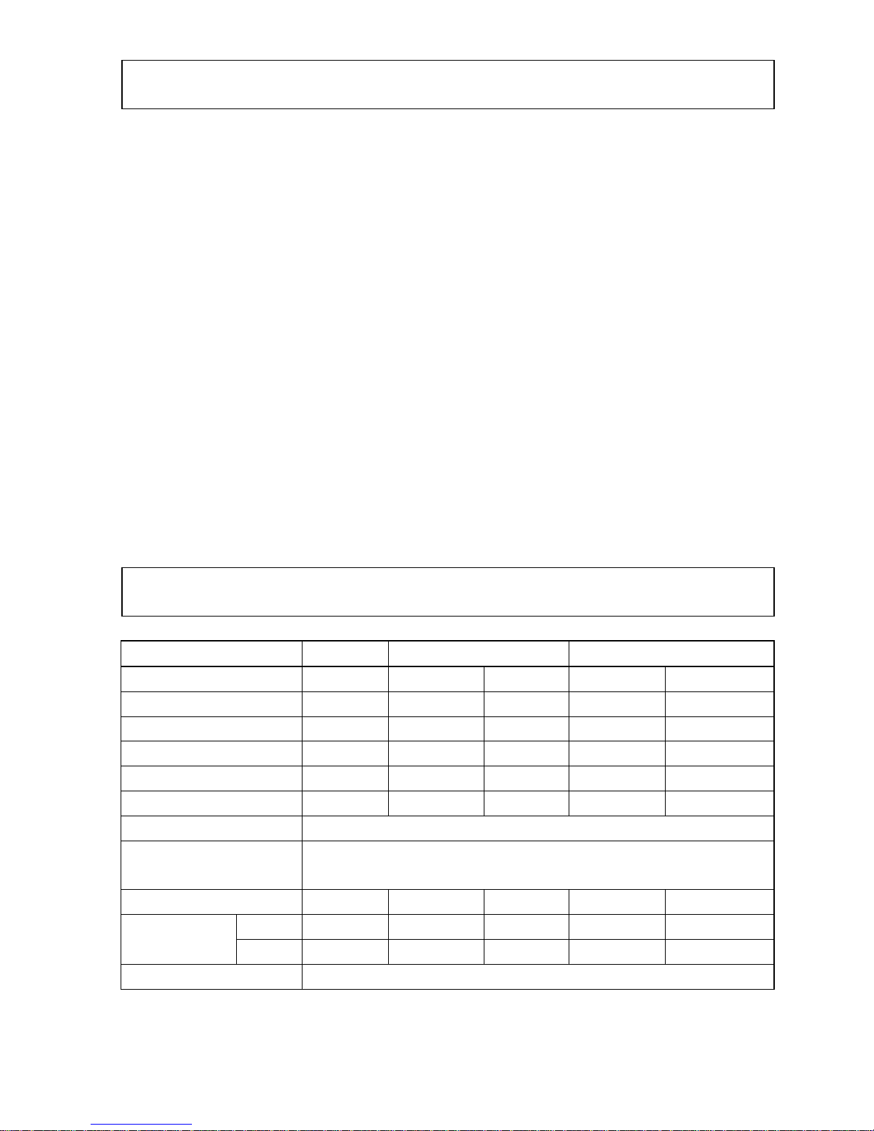
Table of Tightening Torque (kgf-cm) Table 2
Screw diameter
Material 6mm 8mm 10mm 12mm 14mm 16mm 18mm 20mm
4T(SS41) 70 150 300 500 750 1,100 1,400 2,000
6-8T(S45C) 100 250 500 800 1,300 2,000 2,700 3,800
11T(SCM3) 150 400 800 1,200 2,000 2,900 4,200 5,600
In case counter
part is made from
aluminum
100 300〜350 650〜700
※For indication in SI Unit (International Unit System), use the conversion of 1kgf-cm=9.80665N-cm
5. Disassembly work should be conducted where it is free from dust.
6. Where bonding agent such as Loctite has been in use and screw is hard to loosen, heat it with torch
lamp or the like. Such heated bolt must be replaced with new one, which is of high-tension type as
specified.
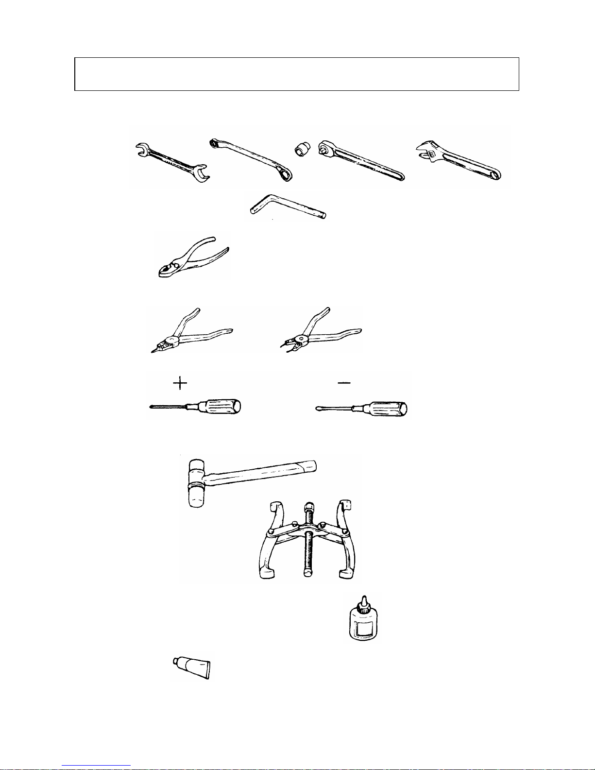
7. Use proper tool in proper manner.
Hydraulic hose tightening torque: Screw size 1/4 380kgf‑cm
3

4
=Disassembled operation system=
5-1 OPEARTION SYSTEM (MVH-R60)
Disassembly
1. Removing two bolts (51) causes throttle body (37)
and throttle lever (39) to come off as an assembly.
Removing the double nut (46, 47) causes the
throttle lever to come off the throttle body.For
removing throttle lever off the machine, remove
the throttle wire (50) which has been screwed
down to the engine.
2. Removing bolt (18) causes the travel lever (17) to
come off hand pump (16).
3. Remove hydraulic hose (26) from the elbow of
vibrator shown in the drawing of disassembled
vibrator.
4. Removing four bolts (28) shown in the drawing allows to remove the handle (1) from base.
Reassembly:
Reassemble the system with its disassembly procedure reversed while observing below:
1. For installing the handle assembly (1) to the base, first have the four bolts (28) tightened only
lightly which are fixing the handle bracket (R) and (L) (26, 27) in the developed drawing, and after
adjusting resistance in handle operation by means of double nut (12), retighten them securely.
2. Have the throttle lever resistance adjusted with double nut (46, 47) before fixing the throttle lever
(39) with socket head set screw (45). The nut tightening torque is 120kgf-cm.
3. Set rpm for high speed side of engine (See Table 1) should be adjusted by means of engine set screw
on the engine side.
5. DISASSEMBLING/REASSEMBLING THE MVH-R60~150:
!Note
: Whenever hydraulic hose has been disconnected, apply blank plug to it for prevention of
any dust from entering.
Remove hydraulic hose clamp (27), its retainer bolt (28) and nut (29). Removing two
bolts (21) and nuts (22) allows to remove grip (25) and hand pump (16) from handle (1).

For VIBRO-COMPACTOR MODEL MVR-R60
Reassembling the governor lever assembly:
The governor lever assembly should be totally disassembled except for hollow setscrew (62) and nut M8
(63) (See Fig.A). <Note 1>
(Fig.-A)
Disassembling the Governor Lever Assembly: Disassembled hollow setscrew (62) and thin nut M8 (63)
should be reassembled to be flush with each other as shown
in Photo B and C.
Parts not to disassemble.
Caution! channel
Photo D
20mm
Photo E
Photo B:
Properly done. Photo C:
Correction required.
Reassembling Procedure:
1. Insert the slider (53) into throttle body (51) with its groove coming in the
back. (Photo D)
2. Install the outer governor wire (64). (Photo E)
(In case the end of inner governor wire should be bent, install inner and
outer wires together by taking measures of steps 3 and 4 below to get the
result as shown in Photo H.)
3. Insert inner part of governor wire (64) through throttle body (51)
(Photo F and G)
4. While pulling the end on inner wire which has come out of outer
part of governor wire, rotate it so that the gear teeth of slider is
visible. (Photo
H).
Apply grease.
Teeth should come to surface.
Photo H
Place head in groove.
Photo G
Insert inner part
Photo F
5

5.Assemble plain washer (57) and o-ring (56) to throttle gear (Photo I).
Photo I:
Throttle gear, etc.
Tooth face of throttle gear,
plain washer and o-ring should
be coated with grease.
6. Assemble throttle gear (52) to throttle body (51) as
follows:
Triangle mark
Photo K
Photo J:
Pull the inner part.
①Push-in the governor wire (inner) and shift the
slider (53) all the way to the back (Photo J).
②Install with triangle mark of the throttle gear
coming on top (Photo K)
7. Assemble throttle lever (54) to throttle body (51) (P
*Plain washers s hoto L and M). Throttle body (51)
Belleville spring (58) x 2
Plain washer M10 (57)
Throttle lever (54)
Plain washer M10 (57)
Nut M10 (61)
Cap nut M10 (60)
hould be installed facing each
*T ss of throttle lever should be adjusted
*Tu -in the hollow setscrew (59) to lock the throttle
fter assembling, throttle lever stops when it reaches
other.
ightne
with nut M10 and cap nut M10. To increase
resistance in the movement of throttle lever,
add a plain washer M10 on the back end.
Tightening torque: 120kgf‑cm Photo L:
Assembling the lever
Photo M:
crewHollow sets
rn
lever to throttle gear.
A
top position as shown in Photo M. This is the position
for the maximum engine rpm.
6

5-1 OPERATION SYSTEM (MVH-120)
Disassembling:
1. Removing two bolts (26) allows to remove the
assembly of grip (25), lever bracket (33) and
throttle lever (35).
Disassembled operation system
Removing double nut (36, 37) causes throttle
lever (35) to come off the lever bracket (33).
To remove throttle lever from machine,
remove governor wire which has been screwed
down to engine.
2. Removing the bolt (13) allows to remove
travel lever (12) from hand pump (11).
3. Remove hydraulic hose (19) from the
connector (34) of vibrator shown in the
drawing of disassembled vibrator
4. With the two handle root mounting double nuts (5) removed, taking off the bolt (2) allows to remove
the handle (1) from the base.
! Note:After removing hydraulic hose, apply blind plug to prevent any dust from entering.
Removing hose clamp (20), its mounting bolt (21), hand pump locking nut (18) and two
stud bolts (pump) (16) allows to remove the hand pump (11) from handle (1).
Reassembly:
Reassembly should be conducted with the disassembling procedure reversed while observing below:
1. For installing the handle assembly (1) to the base, first lightly tighten the nut and bolt which have
been tightening the guard hook side of the machine and adjust the resistance of handle movement by
means of double nut (5) before retightening.
2. Resistance of handle movement should be adjusted with double nut (36, 37).
3. Set rpm of the engine on the high speed end should be adjusted on the engine side by means of engine
setscrew.
※Disassembly and reassembly procedures for MVH-150 is identical to those of MVH-120.
7

8
5-2 BASIC MACHINE MVH-R60, 120 and 150 ※MVH-R60 is used as an example.
Disassembly:
1. With four bolts (21) removed, take off the
outer belt cover (20).
2. Remove V-belt (16).
3. With bolt (15) removed, withdraw the
clutch (12).
4. With flat head screw (18) removed, take
off dust cover (17). (Base can be
separated from compaction plate even
without performing the steps 3 and 4.)
5. Remove hydraulic hose which has been
connected to vibrator.
6. After removing four bolts which have been fixing isolation rubber to the base (1), lift the base
assembly upward. The compaction plate assembly will be separated.
Reassembly:
Reassembly should be conducted with the disassembly procedures reversed, while observing below:
1. Coat the bolts and nuts for mounting the isolation rubber with Loctite 242.
2. All the mounting bolts for the basic machine should be coated with Loctite 242.
3. Installation of the clutch should be made with the belt groove coming to the engine side.
R60 main body corollary exploded view
Before removing the hydraulic
hose, ensure the joint area is free
of dirt and other contaminates.

5-3 VIBRATION SYSTEM
During disassembly and reassembly work, use care not damage any parts.
O-ring, oil seal, packing or the like must be replaced with new one.
Disassembly MVH-R60, 120 and 150 ※MVH-R60 is used as an example.
Fig.1
Cylinder
1. Remove any hydraulic hose connection.
2. With vibrator case mounting bolts (46, 47)
removed, separate the vibrator case assembly
from compaction plate (See Fig.1).
3. With four bolts (30) removed, remove cylinder
(29).
4. Disassembling the piston:
4-1 With the vibrator case inverted upside down,
rotate gear in either direction to cause the
piston assembly (15) to be projected from the
vibrator case, before removing the expansion
stop ring (17) from inside of the piston. (Use a
bent nose type stop ring plier for this
purpose.) (See Fig.2)
Fig.2
Piston
Piston
Expansion
stop ring
Gear
4-2 Withdraw the piston.
4-3 With the contraction stop ring (14) removed,
take off bearing (13) and expansion stop ring
(17) which had been removed earlier (See
Fig.3).
Fig.3
Contraction stop ring
Bearing
Expansion stop ring
9

10

Pendulum shaft (driven)
11
(MVH-R60)
4-4 Remove seal cap (27).
4-5 Remove pendulums (19, 20) from each
pendulum shaft (See Fig.4).
4-6 Shift the pendulum (driven shaft side) (4) to
one side of the vibrator case (1) and remove
bearing (2) using the pulley puller, before
removing the pendulum assembly from the
vibrator case (See Fig.5).
4-7 Push out the stop ring (5) and gear (driven
shaft side) to one side and pull it out. If the
gear is hard to remove, use the press rather
than tapping on it with hammer. (See Fig.6.)
4-8 Push the knock pin (12), with your finger or
by using a plastic hammer if it is sticky, which
will allow to pull out piston rod (11) from the
pendulum shaft (See Fig.7).
(MVH-120AND 150)
4-4 Remove seal cap (25).
4-5 Remove pendulum (18) from each pendulum
shaft (See Fig.8).
4-6 With the driven shaft assembly pushed out to
the side opposite to pulley and the bearing (2)
taken out, remove the driven shaft assembly
from the vibrator case (See Fig.8).
4-7 Disassembling the driven shaft:
Remove four mounting bolts (10) and take out
bearing holder (8) (See Fig.9).
4-8 Remove four mounting bolts (44) and driven
gear (31). Tap on and remove parallel pin (12)
before pulling out piston rod(11) from driven
shaft (4) (See Fig.10).
With two contraction stop rings (5) removed,
remove 210°cam ring (7) from driven shaft (4)
before removing bearing (9) as well (See
Fig.11).
Pendulums Fig.4
Pendulum shaft (driven shaft side)
Bearing Fig.5
Gear Fig.6
Driven shaft
Fig.11
Fig.10
Fig.9
Fig.8
The side opposite to pulley
Fig.7
Knock pin
Piston rod
Pendulum shaft (driven)

MVH -120, 150 VIBRATOR
1. Models MVH-120 and MVH-150 are
different with respect to bearing (2),
pendulum (18), hex socket head bolt
(19), pendulum pulley (35),
washer (37), mounting bolt (38), belt
cover (lower)(45) and mounting socket
head bolt (46).
2. For MVH-150, three different types of
pendulum pulleys (35) are available
according to engine model.
12

MVH-60, 120AND 150 ※MVH-120 is used as an example:
Disassembling the driving shaft side:
5-1 With its mounting bolt (38) removed, pull out the
pendulum pulley (35) from drive shaft. Have the
key (6) removed as well (See Fig.12).
Fig.12
5-2 With its four mounting bolts removed, remove the
bearing cover (21) (See Fig.12).
5-3 With its four mounting bolts removed, remove
pendulum (18) and push out the drive shaft assembly
to the bearing cover side before removing the bearing
(See Fig.12).
5-4 As shown in Fig.13, remove upper stop ring
(5) and engage supports between the drive
gear (30) and inner surface of vibrator case.
Press the drive shaft from top and remove
drive gear within the vibrator case. The gear
having been pressed-in over the distance of
about 2cm, its removal will be easy beyond
that point.
Support
contraction stop ring
Remove upper
Fig.13
Press
5-5 Pull out the drive shaft from vibrator case.
13

REASSEMBLY
MVH-R60, 120AND 150
●Jigs to be used (3 types)
●Before proceeding with reassembly, remove residual liquid packing thoroughly from mating surface
of vibrator case and compaction plate. Clean and de-grease all the other parts as well.
Jig A Jig B Jig C
●Coat the press-fit area with molybdenum grease.
Belt side
Driven shaft sideDrive shaft side
molybdenum grease.
Coat with
Fig.14Opposite to belt side
Re-assembling the driving shaft:
1. Have both of the two bearings (2) inserted in the
belt side of vibrator case (1) (See Fig.14).
Bearings in use:
MVH-R60: 6206C4
MVH-120: 6307C4
MVH-150: NJ307MC4
2. Within the vibrator case, press the drive gear (7)
into drive shaft (3) with its punched side coming
to top (Opposite to belt side) (See Fig.15).
2-1 Vibrator case is to be supported by means of
Jig B with its belt side coming to bottom.
2-2 Have the key 10x8x19 (6) and upper (opposite
to belt side) stop ring (5) engaged to drive shaft.
After placing such assembly inside the vibrator
case, have the drive gear (7) (with its punched
side coming to top) and stop ring (5) engaged to
halfway of the drive shaft, in such order.
2-3 With the Jig A arranged as shown in Fig.15,
ge the
lower stop ring (See Fig.16).
2-
(2) into drive shaft (See
Fig.17).
Drive side
Bottom Jig B
Jig A
Punched surface
on opposite
to belt side
Press-in
Top molybdenum grease
Coat with
Fig.15
push the drive gear into drive shaft
by means of press and enga
Drive side
Fig.16
Drive side
Fig.17
4 Press the bearing of opposite to
belt side
14

Reassembling the driven shaft:
MVH-120 and 150
1. Insert 210°cam ring (7) to drive shaft (4).
Pay attention to the direction of flange face to
install. (See Fig.18)
Fig.21
Position of pressed-in
parallel pin.
Coat with molybdenum
grease.
Press-in
2. Insert two bearings 6807(9) to driven shaft
from its each end and retain them with stop
ring S-35 (5). Apply flat screw drive blade and
lightly tap on it to make sure that the stop ring
has seated in the groove properly. (See Fig.19)
Fig.18Driven shaft side
Apply
molybdenum
grease
Shifter piston side.
Pay attention o directiont
of flange face.
Fig.19Driven shaft Driven shaft side
Apply molybdenum grease.
Fig.20
3. Insert piston rod (11) to the driven shaft (See
Fig.20).
4. Press the parallel pin (12) via cam ring into piston rod. After pressing it in, make sure that the
parallel pin does not protrude from periphery of the cam ring. (See Fig.21)
5. After inserting driven shaft gear (31) to cam ring
(7), lock it with four hex socket head bolts 6x20 (44).
Driven shaft gear (31) and cam ring should be
aligned with punch marks as shown in Fig.23.
Install Fig.22
Bolts should be coated with Loctite 271.
Tightening torque: 180kgf-cm
Fig.24
6X20
Tightening torque:
180kgf-cm
Loctite 271
Fig.23
Mating punch mark on
driven shaft (31)
Mating punch mark on210°cam ring
15

16
Reassembling the driven shaft:
MVH-120 and 150
6. Install bearing holder (8) to driven shaft gear with
four hex socket head bolts 6x30 (10). (See Fig.25)
7. Fit the driven shaft assembly to vibrator case and
after aligning the punch marks of drive gear (30) and driven gear (31), insert it to bearing (2).
(See Fig.26 and 27.)
(MVH-R60)
1. Fit the piston rod to driven shaft, penetrate
knock pin through center hole and push the
gear to the middle of driven shaft before
inserting bearings from each side (See Fig.28).
2. Install the stop ring (See Fig.28)
Apply Loctite 271 to the bolts.
Tightening torque: 180kgf-cm 180kgf-cm
Apply Locktite 271.
Tightening torque:
Fig.25
Fig.26
Driven shaft
assembl Drive gear (30) Driven gear (31)
Mating punch
marks Fig.27
Piston rod Knock pin
Bearing
Gear
Pulley side
Pulley side
Driven shaft
Align
Fig.28
!Note: When inserting driven gear to driven
shaft, make sure to align the punch
mark of gear with pendulum
installing position of pendulum shaft,
before placing the knock pin in the
spiral groove.
Installing with the phase displaced by
180°, will cause operation of forward
and reverse travel to be reversed.
Also, make sure that piston rod and
gear are installed in proper direction.
(See Fig.28)
○Be sure to apply molybdenum type
extreme pressure grease sufficiently
to the bore of pendulum shaft, piston
rod, spiral portion of the bore of gear,
before assembling.

Reassembling the piston:
MVH-R60, 120 and 150
1. Have the expansion stop ring installed over the
piston rod and insert two bearings before retaining
it with contraction stop ring (See Fig.29). (When
using single shield type bearing, it should be
installed with its seal surface facing outward.)
Contraction
stop ring
Fig.29
Seal surface
Bearing
Contraction
stop ring
○When using commercially available bearing,
use molybdenum extreme pressure type grease
to pack.
○Apply grease to the area of piston rod where
bearing is inserted.
Fig.30
USH packing
2. Install USH packing to piston. (See Fig.30.)
(Push it in with your finger after coating with oil.)
○Make certain that piston has no scar or
scratch.
○Use care not to damage piston.
○Install packing in proper direction.
3. Place the piston over the bearing and push the
assembly into vibrator case, before retaining it
with the expansion stop ring which had been
installed earlier (See Fig.31).
Fig.31
Piston
Expansion
stop ring
○To install the piston, either push it in with
hand or lightly tap on it with plastic hammer.
○When installing the expansion stop ring, use
bent nose type plier and make sure that it has
seated properly in the groove.
○After installation, make sure that the piston
rotates smoothly.
17
This manual suits for next models
2
Table of contents
Other MQ Multiquip Power Tools manuals