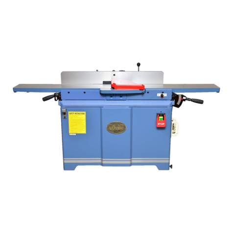
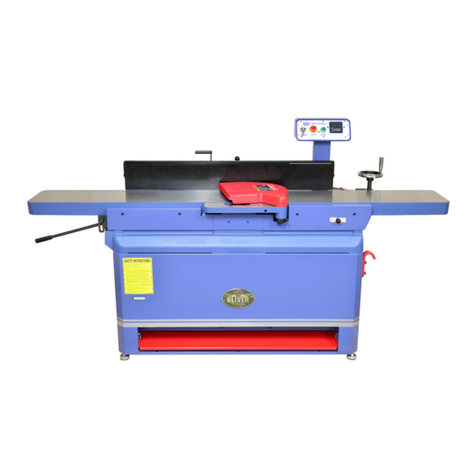
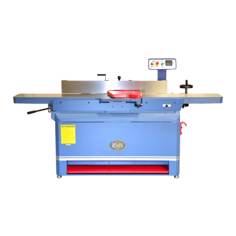
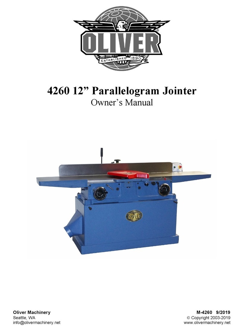
Oliver 0006 User manual

Model 0006
6” Jointer
Owner’s Manual
Oliver Machinery M-0006HS 08/2015
Seattle, WA Copyright 2003-2015

1
Table of contents
SAFETY INSTRUCTIONS .......................................................................................................2
Receiving Jointer......................................................................................................................4
Installation Stand Assembly .....................................................................................................4
Safety Switch ...........................................................................................................................7
Grounding Instructions .............................................................................................................8
Adjustments .............................................................................................................................9
Fence Adjustments: Tilt.........................................................................................................10
Helical Cutterhead..................................................................................................................12
Cutterhead Removal ..............................................................................................................12
Depth of Cut...........................................................................................................................13
Jointing Knives.......................................................................................................................13
Basic Operations....................................................................................................................14
Push Blocks ...........................................................................................................................17
Wiring Diagrams.....................................................................................................................18
Parts Diagrams ......................................................................................................................19
Parts List ................................................................................................................................22

2
SAFETY INSTRUCTIONS
For Your Safety Read Instruction Manual Before Operating Jointer
As with allmachines, there is acertainamount of hazard involved with theuseof thisjointer. Usethemachine with
therespect andcaution demanded where safety precautions areconcerned. When normal safety precautions are
overlooked or ignored, personal injury to theoperator canresult.
Wear eye protection.
Always keep cutter head and drive guards in place and in proper operating condition. Do not remove guard for
rabbeting operations.
Never make jointing , planning, or rabbeting cut deeper than 1/8 in.
Always use hold-down/push blocks for jointing material narrower than 3 inches, or planning material thinner
than 3inches.
Never perform jointing. Planning, or rabbeting cuts (with jointers provided with a rabbeting guard) on pieces
shorter than 8 inches (203 mm) in length.
Keep guards in place and in working order.
Remove adjusting keys and wrenches. Form habit of checking to see that keys and adjusting wrenches are
removed from tool before turning it on .
Keep work area clean. Cluttered areas and benches invite accidents.
Don’t use in dangerous environment. Don’t use power tools in damp or wet locations, or expose them to rain.
Keep work area well lighted.
Keep children away. All visitors should be kept safe distance from work area.
Make workshop kid proof with padlocks, master switches, or by removing starter keys.
.
Don’t force tool. It will do the job better and safer at the rate for which it was designed.
Use right tool. Don’t force tool or attachment to do a job for which it was not designed.
Use proper extension cord. Make sure your extension cord is in good condition. When using an extension
cord, be sure to use one heavy enough to carry the current your product will draw. An undersized cord will
cause a drop in line voltage resulting in loss of power and overheating Table (see Figure 9) shows the correct
size to use depending on cord length and nameplate ampere rating. If in doubt, use the next heavier gage. The
smaller the gage number, the heavier the cord.
Wear proper apparel. Do not wear loose clothing, gloves, neckties, rings, bracelets, or other jewelry which
may get caught in moving parts. Nonslip footwear is recommended. Wear protective hair covering to contain
long hair.
Always use safety glasses. Also use face or dust mask if cutting operation is dusty. Everyday eyeglasses
only have impact resistant lenses, they are NOT safety glasses.
Secure work. Use clamps or a vise to hold work when practical. It’s safer than using your hand and it frees
both hands to operate tool.
Don’t overreach. Keep proper footing and balance at all times.
Maintain tools with care. Keep tools sharp and clean for best and safest performance. Follow instructions for
lubricating and changing accessories.
Disconnect tools before servicing; when changing accessories, such as blades, bits, cutters, and the like.
Reduce the risk of unintentional starting. Make sure switch is in off position before plugging in.

3
Use recommended accessories. Consult the owner’s manual for recommended accessories. The use of
improper accessories may cause risk of injury to persons.
Never stand on tool. Serious injury could occur if the tool is tipped or if the cutting tool is unintentionally
contacted.
Check damaged parts. Before further use of the tools, a guard or other part that is damaged should be
carefully checked to determine that it will operate properly and perform its intended function –check for
alignment of moving parts, binding of moving parts, breakage of parts, mounting , and any other conditions
that may affect its operation. Aguard or other part that is damaged should be properly repaired or replaced.
Direction of feed. Feed work into a blade or cutter against the direction of rotation of the blade or cutter only.
Never leave tool running unattended. Turn power off. Don’t leave tool until it comes to a complete stop.
Do not perform jointing operation on material shorter than 8 in , narrower than 3/4 in, or less than 1/4 in thick.
Do not perform planing operation on material shorter than 8 in , narrower than 3/4 in, or wider than 6”in or
thinner than 1/2 in.
Maintain the proper relationships of infeed and outfeed table surfaces and cutter head knife path.
Support the work piece adequately at all times during operation; mqintain control of the work at all times.
Do not back the work toword the infeed table.
Do not attempt to perform an abnormal or a little-used operation without study and the use of adequate hold-
down/push blocks, jigs, fixtures, stops and the like.
Hand safety. It is good practice to movethehands
in an alternate motion from back to front as thework
continues through thecut. Never pass thehands
directly over thecutter knife. As onehandapproaches
theknives remove it from thestock in an arcmotion
andplace it back on thestock in aposition beyond
thecutterknife.
Three inch rule. When working apiece of wood on
thejointer, follow the3inch radius rule. Thehands
must never be closer than3inches to thecutter head.
Health hazards. Some dust created by power
sanding, sawing, grinding, drilling andother constructionactivities contains chemicals known to cause cancer,
birth defects or other reproductive harm. Some examples of these chemicals are:
*Lead from lead-based paint.
*Crystalline silica from bricks andcement andother masonry products.
*Arsenic andchromium from chemically-treated lumber.
Yourrisk from these exposures varies, depending on howoften youdo this type of work. To reduce your
exposure to these chemicals, work in awell-ventilated area, andwork with approved safety equipment, such
as those dust masks that arespecifically designed to filter outmicroscopic particles.
Familiarize yourself with thefollowing safety notices used in this manual:
CAUTION: (This meansthatif precautions arenotheeded, it mayresult in minor or moderate injury
and/or possible machine damage)
WARNING: (This meansthatif precautions arenotheeded, it could result in serious injury or
!
possibly even death).
!
!

4
Receiving Jointer
Upon delivery, open shipping containers andcheck
that allparts arein good condition. Anydamage
should be reported to your distributor and
shipping agent immediately. Before proceeding
further, read yourmanualandfamiliarize yourself
thoroughly withassembly, maintenance and
safety procedures.
Warning: This machine is very heavy.
Please don’t move or assembly this machine
alone. Ask someone to help for safety required.
Installation Stand Assembly
Showing as below:
Prepare following parts for stand install
A: Stand- Left................................ 1
B: Stand- Right.............................. 1
C: Front Panel............................... 1
D: Motor Bracket ........................... 1
E: Shoulder Screw 5/16”x1/2”........ 12
F: Hex. Nut 5/16”-18NC................. 12
H: Foot Leveling............................ 4
I; Hex. Nut 3/8”-16NC................... 8
J: Flat Washer 10.5x27x2t............. 8
K: Hex. Screw w/washer ............... 3
Step 1: Assembly Stand- Left (A) . Stand- Right (B) &
Front Pane (C) with Shoulder Screw (F)*6 & G Hex.
Nut*6 but not tighten all screws.
Step 2: Put Motor bracket (E) on the stand (step 1)
lock by Shoulder Screw (F)*6 & Hex. Nut (G)*6 but
not tighten all screws.
Step 3: Turn over the stand assembly upside down
then locate Foot (H) . Hex (I). Nut & Flat Washer (J)
on four corners.

5
Installation Motor & Switch
Step 4: Put the motor & switch assembly on the
Motor Bracket (D) and lock by Shoulder Screw
(E)*4 & Hex. Nut (F)*4 but not tighten all screws.
Warning: The motor & switch assembly is
heavy. Do not assemble motor by yourself; ask
someone to help is required.
Step 5: Place to switch into the rectangle hole
on stand-right and tighten by 2 Round Head
phillips screw w/teeth washer (L)
Step 6: The plug (M) need to pass through the
round hole on the stand-right and fix the power
Fixing plate (O) by Round Head phillips screw
w/flat washer (N)* 2
Installation Jointer Body & Stand
Step 7: Put a large clean carton board or plastic paper
on the floor to protect the jointer table top surface.
Step 8: Turn over the jointer Body then put the stand
of step 6 to the jointer base by 3 Hex. Screw
w/washer 3/8”x16NCx3/4”(P) but not tighten all
screws
Warning: The jointer body & stand are heavy.
Be careful and asking help when needed.
Installation V-Belt
Step 9: To attach the V-belt over cutterhead pulley
and motor pulley.
Stand-Right
Switch
L
Stand-Right
M
O
N
Motor
E
F
D
Jointer Body
Stand
P
V-Belt

6
Checking Belt Tension
Step 10: Pull down on the motor to achieve the
desired belt tension (the correct belt tension is
achieved when the belt can be deflected
approximately one inch at the center belt span
using light finger pressure) Snug tight the 4
Shoulder Screw (E) & Hex. Nut (F).
Installation Rear Panel
Step 11: Assembly the rear panel after the V-
belt adjustment with 3 Shoulder Screw (E) &
Hex. Nut (F) then tighten all of screws on the
stand assembly.
Then Turn over the jointer .
Warning: The jointer with stand is heavy.
Be careful and asking help is required.
Installation Pulley Cover
The pulley cover is mounted with 2 Round Head
phillips screw w/teeth washer (L) to the threaded
holes in the Stand.
Installation Fence
1. Take the lock Knob (R), flat washer (S), and lock
nut (T) from the hardware bag..
2. Place the Key (U) on the Fence bracket slot then
put the fence assembly onto the table (B) Be sure
the key stock (U) on the bed lines up with the
channel (V) in the fence casting.
3. Place the flat washer (S) on slot (W); insert the
lock Knob (R) through the fence casting and the
table casting.
4. Thread the lock nut (T) onto the lock Knob
(R). Make sure the tab on the nut faces up and
engages the slot in the table casting.
R
S
U
T
Fence Assembly
W
V
L
E
F

7
Installation Blade Guard & Removal
WARNING: Use the jointer guard for all
operations. Do not connect the plug to power
source
1. Loosen the Round Head phillips screw
(A)from guard post (Z)
2. Turn knob (Y) counterclockwise to create
tension on spring, and hold it there.
3. Insert guard post (Z) down through hole in
front of ledge.
4. Slightly turn knob (Y), if necessary, until
the guard seats itself, and the spring
engages the slot at the end of the guard
post.
5. Check the guard for proper tension. If
guard does not spring back into place
when pulled back from cutterhead, remove
guard and adjust spring tension by repeating
steps 1-3 until correct tension is achieved.
NEVER run the jointer without the guard
being in place and in perfect working order.
6. Tighten the Round Head phillips screw
(A)from guard post (Z)
Installation Dust Chute
Mount the dust chute to the pre-tapped holes in
the side of the stand with 2 wing screws (A) .
Installation Handwheel
Slip the handwheel (B) onto the elevation shaft (C)
(under the infeed table) then tighten with the Round
Head phillips screw w/washers (D)
Installations are completed.
Safety Switch
This Jointer has a rocker style switch with a
removable locking key to prevent unauthorized
use. If you intend to be away from the machine for
a long period of time and there is any chance of its
use by others, especially children, Remove the
lock key with the switch in the “OFF”position.
Store it in a safe, inconspicuous place in your
workshop. To turn the planer on, insert the red
locking key and turn the switch to the ON position.
The planer will then be operable. To turn the
planer off, turn the switch to the “OFF”position.
WARNING: Always be sure the switch is in the
“OFF”position before connecting the
jointer to the power source.
A
Y
Z
X
B
C
D
Lock Key
Switch Assembly

8
Grounding Instructions
WARNING: If themachine doesnotcome
wired to run, theelectrical andmotor
wiring mustbe doneby aqualified
electrician. Themachine mustbe
properly grounded to help avoid
electrical shock andpossible death.
Follow therecommendations made by
theNational Electrical Code for
grounding.
1. Allgrounded, cord connected tools:
In theevent of amalfunction or breakdown, grounding
provides apath of least resistance for electric current to
reduce therisk of electric shock. This tool is equipped
with an electric cord having an equipment- grounding
conductor andagrounding plug. Theplug must be
plugged into amatching outlet thatis properly installed
and grounded in accordance with all localcodes and
ordinances. Do notmodify theplug provided -if it will
notfittheoutlet, have theproper outlet installed by a
qualified electrician.
Improper connection of theequipment-grounding con-
ductor canresult in arisk of electric shock. The
conductor with insulation having an outer surface
that is green, with or without yellow stripes, is the
equipment-grounding conductor. If repairor
replacement of theelectric cord or plug is necessary,
do notconnect theequipment-grounding conductor to
aliveterminal. Check with aqualified electrician or
service personnel if thegrounding instructions are
notcompletely understood, or if in doubt as to
whether thetool is properly grounded.
Useonly3-wire extension cords thathave 3-prong
grounding plugs and3-polereceptacles that accept
thetool’splug.
Repair or replace damaged or worn cord immediately
2. Grounded, cord-connected tools intendedforuseon a
supply circuit having anominal rating less than
150 volts:
This toolis intended foruseon acircuit that hasan
outlet that looks like theoneillustrated in Sketch A,
Fig. 1. Thetoolhasagrounding plug thatlooks like
theplug illustrated in Sketch A.
Atemporary adapter, which looks like theadapter il-
lustrated in Sketches BandCin Fig. 1,maybe
used to connect this plug to a2-polereceptacle as
shown in Sketch Bif aproperly grounded outlet is not
available. Thetemporary adaptershould be used only
until aproperly grounded outlet canbe installed by a
qualified electrician. Thegreen-colored rigid ear, lug,
andthelike, extending from theadaptermust be
connected to a permanent ground such as aproperly
grounded outlet box.
Note: In Canada, the use of a temporary adapter is
not permitted by the Canadian Electrical Code
3. Grounded, cord-connected tools intended for use
on a supply circuit having a nominal rating between
150-250 volts, inclusive:
This tool is intended for use on a circuit that has an
outlet that looks like the one illustrated in Sketch D
Fig. 1. The tool has a grounding plug that looks like the
plug illustrated in Sketch D.
Make sure the tool is connected to an outlet having the
same configuration as the plug. No adapter is available or
should be used with this tool. If the tool must be
reconnected for use on a different type of electric circuit,
the reconnection should be made by qualified service
personnel and after reconnection, the tool should comply
with all local codes and ordinances.
Extension Cords
Useproper extension cord. Makesure your extension
cord is in good condition. When using an extension cord,
be sure to useoneheavy enough to carry thecurrent your
product will draw. An undersized cord will cause adrop in
linevoltage resulting in loss of power andoverheating.
Fig. 2 shows thecorrect size to use depending on cord
length and nameplate ampere rating. If in doubt,usethe
nextheavier gauge.The smaller the gauge number, the
heavier the cord.
Rewiring Motor for 230Volts
When rewiring thesupplied electric motorfor230volts, be
sure power cord is unplugged then change the
connections as illustrated in the diagram in the motor wiring
box.Always secure wire nuts with friction tape.
Anew plug will be required for 230 volts as illustrated in Fig.
1, Sketch D.
Fig. 1
Note: In Canada, the use of a temporary adapter is not
permitted by the Canadian Electrical Code.
Ampere Rating
Volts
Total
length
of
cord
in
feet
Ampere Rating
115/230
25'
50'
100'
150'
More Not
Than More
Than
AWG
0
6
6
10
10
12
12
16
18
16
16
12
18
16
14
12
16
16
14
12
14
12
Not r
ecommended
Fig. 2
Note: The reconnection shall be made by qualified
service personnel.
!
GROUNDING PIN

9
Adjustments
Warning: Always disconnect the machine from
the power source before making any
adjustments..
Failure to heed this warning can lead to serious
personal injury.
Note : Clockwise raises the table,
counterclockwise lowers thetable.
To adjust outfeed table
The Jointer table is adjusted at manufactory and
should no further adjustment required. To align
the tip of knife & outfeed table as below if
necessary.
1. Loosen thumb screw (A), Fig. 3
2. Turn Knob (B) under the outfeed table.
3. Put a straight gauge (C) on the outfeed
table extending over the cutter head then
rotate the cutterhead by hand until the
knife tip just touch the straight gauge,
Fig. 4
4. When set, retighten thumb screw (A).
To adjust infeed table:
1. Loosen the thumb screw (D), Fig. 5
2. Place a straight gauge (C) cross the
outfeed table & infeed table
3. Turn the handwheel (E) until the outfeed
table & infeed table on the same level.
4. Tighten the thumb screw (D).
5. Loosen Round Head phillips screw (F),
Fig.6 then adjust the pointer (G) by hand
until the pointer line alignment with scale
“0”.
NOTE: Thefine adjustment handle has1/16"
travel per rotation.
Warning: There is a Depth Stop Limited on the
back side that must be released if
cutting a depth greater than 1/8".
If hand wheel seems jammed, please
check and release the Depth Stop
Limiter on the front of jointer.
Fig. 3
Fig. 4
Fig. 5
Fig. 6
A
B
D
E
D
C

10
Table Gibs and Leveling
Thetable gibs on your machine are factory
adjusted andmay never require readjustment.
Should anyadjustment become necessary, do
thefollowing:
1. Lightly loosen the 2 wing screw (A), Fig. 7.
By loosening 6 lock nuts (B) then tighten 6
Set screws (C) , should be loose enough to
move the table.
2. Tighten 2 Wing screws
3. Support theendof thetableandatthe
same time, raise it up slightly. Snug the gib
screws. Anyadjustment of thegibs is very
minute, perhaps even 1,000th of an inch. If
the gibs are too tight the adjustment handles
will be difficult to turn. If thegibs ar etoo
loose the tables could sag. Keep checking
the level of thetables withastraightedge until
leveling is achieved. Whentables are level,
tighten the lock screws.
Warning: It is recommended thatanother
person holdandsupport thetable when
performing these adjustments.
Fence Adjustments: Tilt
Fence adjustments are made with the lock
knob (D) shown in Fig. 8
To slide the fence forward or back on the table,
loosen lock knob (D), slide the fence to the
desired position and tighten lock knob (D) to
secure fence.
To tilt the fence forward:
1. Loosen locking handle (E), Fig. 8
2. Place a machinist protractor or triangle on
the table and against the fence. Adjust the
fence to the desired angle and tighten
locking handle (E) to secure the fence.
To tilt the fence back:
1. Loosen locking handle (E), Fig. 8
2. Flip back the stop block (F).
3. Adjust the fence to the desired angle and
tighten locking handle (E) to secure fence.
Caution: When the jointing operation is finished
with the fence tilted back, do not forget to flip
the pivot stop block back to its original position.
Fig. 7
Fig. 8
NOTE: The lock knob (D, Fig. 8) can be adjusted to
a more convenient position by loosening the
nuts on its opposite end, turning the handle
to the proper position, and retightening the
nuts.
B
C
A
E
D
F

11
Fence Stop Adjustments
Periodically check the 90° and 45° backward
(135°) tilt accuracy of the fence with an angle
measuring device, such as an adjustable
square or machinist’s protractor.
90º Fence Adjustment
Referring to Fig. 9 :
The 90º stop is controlled by the stop bolt (A)
and the stop plate (B).
1. Set the infeed table to approximately the
same height as the outfeed table.
2. Move the fence by releasing lock knob (D)
and pushing the fence assembly until it
overlaps the tables.
3. Tighten lock knob (D).
4. Adjust the fence to a 90º angle by releasing
lock handle (C).
Note: The stop bolt (A) should be resting
against the stop plate (B).
5. Place an angle measuring device (H)
Fig.10 on the table colsed to fence surface
and pulling up the fence handle (G) to
confirm a 90º setting then tightening the lock
handle (C).
6. Loosen the hex nut (E) until the stop bolt
head (A) touch stop block (F) surface.
7. Tighten the hex nut (E) to retain the setting.
8. Double check to the fence is setting square
with table .
45º & 135 º Fence Backward Stop Adjustment
Referring to Fig. 11:
Note: The 45º fence backward stop is
controlled by the stop bolt (A) and 135 º fence
backward stop is controlled by the stop bolt
(B).
1. Loosen the lock knob (D). Move the stop
plate (E) out of the way and position the
fence at the 45 º or 135º angle. Make
sure the fence sits against on the correct
stop bolt.
2. Tighten the lock knob (D)
3. Place an angle measuring device on the
table Fig. 12 and against the fence to
confirm 45 º & 135º setting (A Fig.27).
4. To adjust, loosen the lock nut (F) or (G) ,
turn the stop bolt (A) or (B) until a 45 º or
135º angle is obtained.
5. Tighten the lock nut (F) or (G).
6. Double check to the fence is setting correct
angel with table .
Fig. 9
Fig. 10
Fig. 11
Fig. 12
H
A
B
D
C
E
F
G
F
G
D
C
E
B
A
45 º
135º

12
Helical Cutterhead
WARNING: Knife inserts are dangerously sharp.
Use extreme caution when inspecting,
removing or replacing knife inserts.
The knife inserts on the Jointer are four-sided.
When dull, simply remove each insert, rotate it
90° for a fresh edge, and re-install it. No further
adjustment is necessary. Use the two provided
torx wrench to remove the knife insert screw.
Use one of the torx wrenches to help hold the
cutterhead in Position, and the other to remove
the screw. See Fig. 13. It is advisable to rotate
all inserts at the same time to maintain
consistent cutting. However, if one or more
knife inserts develops a nick, rotate only those
inserts that are affected.
Each knife insert has an etched reference mark
so you can keep track of the rotations.
IMPORTANT: When removing or rotating
inserts, clean saw dust from the screw, the
insert, and the cutterhead platform. Dust
accumulation between these elements can
prevent the insert from seating properly, and
may affect the quality of the cut.
Before installing each screw, lightly coat the
screw threads with machine oil and wipe off any
excess.
Securely tighten each screw which holds the
knife inserts before operating the jointer!
Make sure all knife insert screws are tightened
securely. Loose inserts can be propelled at high
speed from a rotating cutterhead, causing injury.
FIG. 13
Cutterhead Removal
If removal of the cutterhead is necessary, do the
following:
WARNING: Disconnect jointer from
power source.
1. Remove the entire fence assembly by
releasing lock handle and removing hex nuts
(see page 6) lift the fence off the machine.
2. Loosen the bolts connecting the motor to the
motor mount and remove the drive belt from
cutterhead pulley (see page 5).
3. Lower bothinfeed andoutfeed tables to
expose the cutterhead.
4. Remove the two bolts and spring washers
which secure the cutterhead to thebase, as shown
in Fig. 14
5. Remove the cutterhead assembly, with studs
attached, by lifting cutterhead straight up from
base. Thebeltpulley maybe left on cutterhead
to assist in raising the cutterhead.
6. Remove pulley andbothbearing housings
withattached studs fromthecutterhead.
NOTE: You maywishto keep on handan extra
cutterhead in order to maintainshop productivity.
7. When mounting newcutterhead to base, make
sure thecurved seats of thebasearecleaned and
free of dust andgrease.
FIG. 14
!

13
Depth of Cut
Depth of cut is determined by the height of the
infeed table relative to thehigh point of the
knives on thecutterhead.
When facing thewidth of aboard(asopposed to
theedgeof aboard), NEVER attempt to take
offmore than 1/64" witheachpass.
Thedepth of cut is indicated by thescale located
on thefront of thejointer baseas shown in
Fig. 15.
Jointing Knives
After extended use it will be necessary to
sharpen the knives on the cutterhead assembly
so that all knives protrude exactly the same
height above the cutterhead .
To joint the knives:
WARNING: Disconnect machine from
power source. Use approved eye
protection whenever sharpening blades.
FIG. 15
FIG. 16
1.Remove the cutterhead guard
2. Place a metal straightedge across both
tables as shown in Fig.16, and make
sure both tables are set t o the exact
height o f the high point of the knives.
3. Clamp a block of wood across the infeed
table as shown in Fig. 17 in order to block
the end of a fine India stone or oilstone
during the jointing operation. This helps to
prevent kickback of the stone.
4.Turn machine on.
5. Keeping hands well clear of the cutterhead,
place the stone into position as shown in
Fig. 17, and slide the oilstone back and
forth across both tables until the knives are
lightly jointed.
6. TURN MACHINE OFF and visually inspect each
knife. If only the high knife has been touched,
lower the OUTFEED table 0.003”and
continue the sharpening process until all three
knives have been touched by the stone.
7. Replace cutterhead guard.
FIG. 17
!

14
Basic Operations
Before making any cuts on the stock, make a
few practice cuts by raising the infeed table to
“ 0" and with the power disconnected. In this
manner you will acquaint yourself with the feel
of jointer operations.
Surfacing
twohandedpush
block
Adjust depth of cut. It is better to makecuts of
approximately 1/64 inch. Thiswill enable you
to have better control over thematerial being
surfaced. Make several passes if necessary to
obtain proper stock removal.
Never surface pieces shorter than 12inches or
thinner than3/8 inchwithout the useof a
special work holding fixture. Never surface
pieces thinner than3inches without the use of
apushblock. On stock 8" to 12"longusea
single two-handed push block (Fig. 18). On
stock longer than12 inches usetwo push
blocks (Fig. 19). Withnarrow stock usethe
type push block shown in Fig.20.When
surfacing shortstock over 4inches wide, use
two (2) pushblocks to guide material over
cutterhead (Fig. 21).
L-shaped push block
for narrow stock
twopush blocks
forstock longer
than 12 inches
FIG.18
FIG. 19
twopush blocks
with dowels
forshort stock
over 4inches wide
FIG. 20
FIG. 21

15
Surfacing: Long Boards
Theuseof pushblocks willhelpto insure
against hands coming in contact with cutterhead
in the event of akickback andas trailing endof
board passes over cutterhead.
When surfacing longstock, place pushblock
nearthefront of piece andstart feeding wood with
the right hand until guard has opened and cut is
started (Fig. 22).
Place second pushblock near the rear of infeed
table and continue feeding stock using the hand
over hand method (Fig. 23).
Before the left hand is in the 3 inch area of the
cutterhead move it over to the outfeed side
(Fig. 24).
As soon as possible follow with the right hand
over to the outfeed side and continue through
with cut (Fig.25).
Begin by feeding stock with right hand and
apply pressure to front of stock with push block.
When the stock is longer than twice the length
of the infeed and outfeed tables, another
helper or support table must be used to
support the stock.
FIG. 22
FIG. 23
FIG. 24
FIG. 25
On outfeed
Side both hands
pull stock through
left handis
moved to outfeed side
near cutter,
feed hand
over hand
left hand pushes
down toward fence
as right hand
starts feed

16
Jointing (or Edging)
Never edge a board that is less than 3 inches
wide, less than 1/4 inch thick, or 12 inches
long, without using a push block.
move fence forward
to expose only amount
of cutterhead required
CAUTION: When workpiece is twice the
è
length of the jointer infeed or outfeed
table use an infeed or outfeed support .
Begin by feeding stock with right hand and
apply pressure to front of stock with push block.
When edging, make cuts of approximately 1/16
inch for hardwood and 1/8 inch for softwood.
When edging wood wider than 3 inches lap the
fingers over the top of the wood, extending
them back over the fence such that they will act
as a stop for the hands in the event of a
kickback. Keep stock against the fence
(Fig. 26).
Beveling
When beveling never make cut deeper than
1/16 inch. Make certain material being beveled
is over 12 inches long, more than 1/4 inch thick
and 1 inch wide. Set fence to desired angle.
FIG.26
FIG. 27
CAUTION: Although fence may be tilted in
or out for bevel cut, We recommends for
safety reasons the fence be tilted in,
if possible, making a cradled cut (Fig. 27).
For wood wider than 3 inches, hold with fingers
close together near the top of the stock, lapping
over the board and extending over the fence.
When beveling material less than 3 inches wide,
use beveled push blocks and apply pressure
toward the fence. Keep fingers near top of
push block (Fig. 28).
When beveling short material use one bevel
hold down and apply pressure toward the fence.
Keep thumb above the ledge on hold down
block (Fig. 29).
Cross Grain
NOTE: When beveling around four edges of a
workpiece, make cross grain cuts first. This will
help clean up any chipping or splintering when
beveling the end grain.
For long boards, follow the same hand-over-
hand procedure used for surfacing long boards.
FIG. 28
FIG. 29
!
!

17
Skewing (Shear Cutting)
When edging or facing burl or birds-eyemaple,
it is notunusual to deface or marthesurface
being finished. This is caused by the
cutterhead blades attimes cutting against the
grain. In order to prevent the defacing or
marring of this type wood, it is necessary to skew,
or anglefinish, thematerial being worked. See
Fig. 30.
1. Release the fence locking handle and
remove the two hex nuts and flat washer
holding the fence to the fence support (see
page 4). Remove the fence.
2. Remove the key from the fence slide base.
3. Replace the fence assembly at the desired
angle across the cutterhead. Secure the
fence to the support with the two hex nuts
and flat washer, then tighten the fence
locking handle.
Push Blocks
Push blocks are simple, yet necessary tools to
assist the operator especially when jointing thin
or short stock. Illustrated in Figure 32 are three
types of push blocks commonly used in jointing.
Push blocks may be obtained commercially or
easily constructed.
NOTE: The Jointer is supplied with two push
block for feeding stock as below showing
FIG. 30
FIG. 31

18
Wiring Diagrams

19
Parts Diagrams
Table of contents
Other Oliver Power Tools manuals

Oliver
Oliver 4235 User manual

Oliver
Oliver 4270 User manual

Oliver
Oliver 10060.001 User manual

Oliver
Oliver 4265 User manual

Oliver
Oliver 4240 User manual

Oliver
Oliver 4265C Instruction Manual

Oliver
Oliver 10047VS User manual

Oliver
Oliver 4260 User manual

Oliver
Oliver M1013 User manual

Oliver
Oliver 4235 User manual
Popular Power Tools manuals by other brands

Sparx
Sparx S200 operating manual

Chicago Electric
Chicago Electric 40208 Assembly and operating instructions

Ryobi
Ryobi 3001953 user manual

Sharpe
Sharpe RAZOR 24A525 Series Instructions-parts list

Atlas Copco
Atlas Copco ETV STB63-50-10-IRC-B Original product instructions

Makita
Makita AN901 instruction manual