5
• The installation should be done by a qualified HVAC contractor. Unit must be installed in compliance with all
national and local electrical and mechanical codes. Failure to do so will void ETL safety listing and Second
Wind warranty.
• Read all safety instructions at the beginning of this manual. Failure to do so could lead to personal injury and/
or equipment damage.
• In cases where molds are already present on the evaporator coil, it is recommended that a qualified HVAC
technician clean the coil before the installation of the UV lamp.
• Safety interlock switches for the access panel are recommended but not supplied.
• Make sure the rooftop unit power has been shut off at the main power source before
installation.
• Protect all non-UV resistant materials from direct UV exposure with aluminum tape
or metal conduit.
• CAUTION: Ultraviolet light can be harmful to your sight, do not look at the lamp
when it is illuminated.
1. Using the Second Wind NEMA unit as a template, mark the (4) mounting holes on the surface where the device
is to be installed.
2. Open the enclosure wit flat screwdriver.
3. Mark the Ø7/8 conduit hole location for the electrical supply.
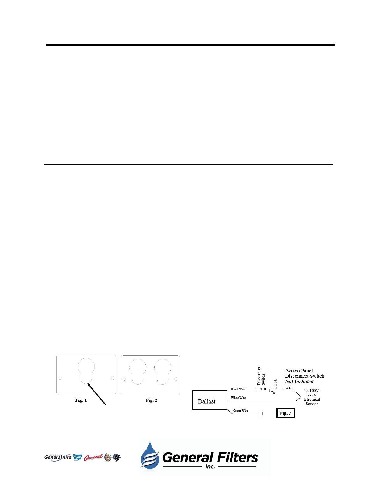
4. For 3000 Series units, mark the position of the smallest diameter on keyhole lamp plate (Fig. 1).
5. For 2000-230OD, and trace perimeter of rectangle cutout on enclosure.
6. Cut electrical access hole and lamp access hole or cutout, depending on model, remove all metal and clean
rough edges to prevent damage to unit.
7. Secure NEMA encloser in position and secure with appropriate hardware (not included).
8. Ensure that NEMA enclosure fits flush against the equipment or duct to ensure gasket seal of joint. Seal
perimeter of enclosure with outdoor silicone.
9. Remove lamp(s) from tubes inside carton, use an alcohol wipe to remove any dirt or fingerprints from the lamp
if present.
10. 3000 Series—insert the lamp into the larger diameter of keyhole, and lower into the smaller diameter. Ensure
that the lamp is secured in lower diameter.
11. 2000-230OD only—perform same as #10 on lamp bracket assembly, then secure opposite end of lamps in
spring clamps at end of assembly. Install in NEMA enclosure and secure with locknuts.
12. Attach the lamp connector to the lamp. There is only one way to attach the connector to the lamp. If it does
not go on, rotate the connector 90 degrees and try again.
13. With the cover of the NEMA enclosure still open, access the ballast and wiring. Install the proper
weatherproof conduit on the bottom of the enclosure. Connect the electrical service through the conduit.
Connect the black and white wires to power and the green wire to ground. Install access panel disconnect
switch, NOT INCLUDED. Refer to the wiring diagram (Fig. 3).
14. Place warning labels (included) on the equipment near installed unit or near the power supply.
15. Close the cover, screw the cover closed to make sure the safety interlock switch is activated. Turn on electrical
service, unit is always energized.
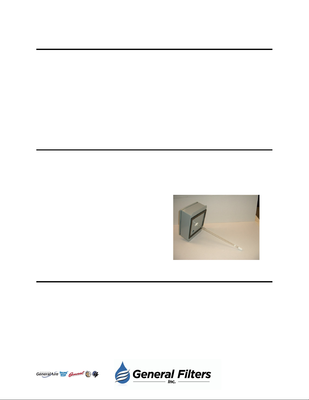
Installation
Lamp sets in
bottom of keyhole
5
43800 Grand River Ave.
Novi, MI 48375
(866) 476-5101
www.generalfilters.com
Our Brands: