GENERAL RADIO COMPANY
MICROSECONDS
DEL.RANGE DEL. CONTROL
DIRECT
I
I
I
TRIGGER DELAY DELAY
CONTROL
-+
SWEEP AMPLITUDE RESET
FROM
INPUT
'
STAR?
BISTABLE
GENERATOR COMPARATOR TRIGGER
AMPLIFIER
-
SYNC GATE
CIRCUITS STOP DELAY RESET TRIGGER
4
COINCIDENCE COINCIDENCE
GATE DURATION SENSITIVITY DELAY ED TRIGGER TO SWEEP
C
?-
3-1000pSEC COINCIDENCE DEL.SYNC
,
MONOSTABLE-
AMPLIFIER
L
TRIGGER
JL
"
AMP.
B
C.F.
GATE
I
COINC.
0
POS,
DRIVE
4
INVERTER
::?ti
1-
PANEL
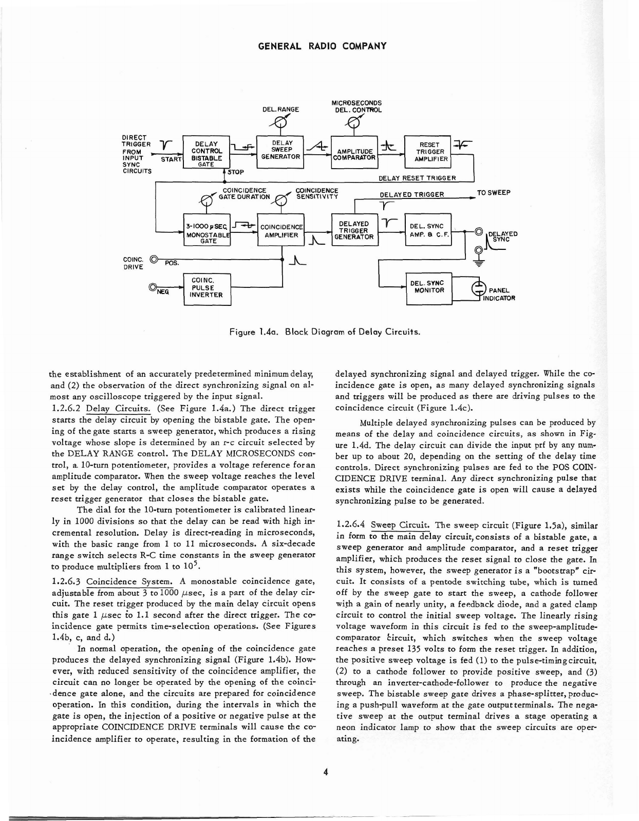
Figure 1.4a. Block Diagram of Delay Circuits.
the establishment of an accurately predetermined minimumdelay,
and (2) the observation of the direct synchronizing signal on al-
most any oscilloscope triggered by the input signal.
1.2.6.2 Delay Circuits. (See Figure 1.4a.) The direct trigger
starts the delay circuit by opening the bistable gate. The open-
ing of thegate starts a sweep generator, which produces a rising
voltage whose slope
is
determined by an r-c circuit selected by
the DELAY RANGE control. The DELAY MICROSECONDS con-
trol, a. 10-turn potentiometer, provides a voltage reference foran
amplitude comparator. When the sweep voltage reaches the level
set by the delay control, the amplitude comparator operates a
reset trigger generator that closes the bistable gate.
The dial for the 10-turn potentiometer
is
calibrated linear-
ly in 1000 divisions so that the delay can be read with high in-
cremental resolution. Delay
is
direct-reading in microseconds,
with the basic range from
1
to
11
microseconds. A six-decade
range switch selects R-C time constants in the sweep generator
to produce multipliers from
1
to
lo5.
1.2.6.3 Coincidence System. A monostable coincidence gate,
adjustable from about
3
to1000 psec, is a part of the delay cir-
cuit. The reset trigger produced by the main delay circuit opens
this gate
1
psec to
1.1
second after the direct trigger. The co-
incidence gate permits time-selection operations. (See Figures
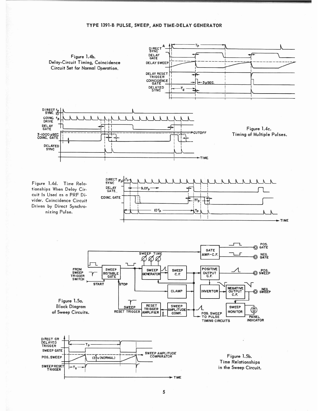
1.4b, c, and d.)
In normal operation, the opening of the coincidence gate
produces the delayed synchronizing signal (Figure 1.4b). How-
ever, with reduced sensitivity of the coincidence amplifier, the
circuit can no longer be operated by the opening of the coinci-
.dence gate alone, and the circuits are prepared for coincidence
operation. In this condition, during the intervals in which the
gate
is
open, the injection of a positive or negative pulse at the
appropriate COINCIDENCE DRIVE terminals will cause the co-
incidence amplifier to operate, resulting in the formation of the
delayed synchronizing signal and delayed trigger. While the co-
incidence gate
is
open, as many delayed synchronizing signals
and triggers will be produced as there are driving pulses to the
coincidence circuit (Figure 1.4~).
Multiple delayed synchronizing pulses can be produced by
means of the delay and coincidence circuits, as shown in Fig-
ure 1.4d. The delay circuit can divide the input prf by any num-
ber up to about 20, depending on the setting of the delay time
controls. Direct synchronizing pulses are fed to the
POS
COIN-
CIDENCE DRIVE terminal. Any direct synchronizing pulse that
exists while the coincidence gate
is
open will cause a delayed
synchronizing pulse to be generated.
1.2.6.4 Sweep Circuit. The sweep circuit (Figure 1.5a), similar
in form to the main delay circuit,consists of a bistable gate, a
sweep generator and amplitude comparator, and a reset trigger
amplifier, which produces the reset signal to close the gate. In
this system, however, the sweep generator
is
a "bootstrap* cir-
cuit. It consists of a pentode switching tube, which
is
turned
off by the sweep gate to start the sweep, a cathode follower
with a gain of nearly unity, a feedback diode, and a gated clamp
circuit to control the initial sweep voltage. The linearly rising
voltage waveform in this circuit
is
fed to the sweep-amplitude-
comparator kircuit, which switches when the sweep voltage
reaches a preset 135 volts to form the reset trigger. In addition,
the positive sweep voltage
is
fed (1) to the pulse-timingcircuit,
(2) to a cathode follower to provide positive sweep, and
(3)
through an inverter-cathode-follower to produce the negative
sweep. The bistable sweep gate drives
a
phase-splitter, produc-
ing a push-pull waveform at the gate outputterminals. The nega-
tive sweep at the output terminal drives a stage operating a
neon indicator lamp to show that the sweep circuits are oper-
ating.