GENERAL RADIO COMPANY 1650-B User manual

DANCE

INSTRUCTION MANUAL
IMPEDANCE
BRIDGE
Form
165@012@A
ID-0100
April,
1968
GENERAL
RADIO
West
Concord,
Massachusetts
Copyright
1968,
General Radio Company

Specifications
RANGES OF MEASUREMENT ACCURACY
t
Bridge operates up to
100
kHz
with reducedaccuracy.
GENERAL Accessories Required: None. Earphones can be used for high
Generator: Internal;
1
kHz
22%.
Type
1310
or
1311
Oscillator precision at extremes of bridge ranges.
recommended if external generator is required. Internal dc sup-
~~~~~~~~i~~
~~~il~bl~:
T~D~
1650-P1
~~~t
jig.
Residuals
=0.5
pF
=
0.2
pH
=lmR
.
.
ply,
6
V,
60
mA, max. Mounting: Flip-Tilt Cabinet.
Detector: Internal or external; internal detector response flat or
selective at
1
kHz; sensitivity control provided. Type
1232-A
Dimensions (width x height x depth): Portable,
13
x
6Y4
x
121/4
in.
Tuned Amplifier and Null Detector is recommended if external
(330
x
175
x
315
mm); rack,
19
x
121/4
x
4%
in.
(485
x
315
x
detector is required. Combination of
1311
oscillator and
1232
de-
105
mm).
tector is available as the Type
1240
Bridge Oscillator-Detector. Net Weight (est): Portable,
17
Ib
(8
kg); rack,
18
Ib
(8.5
kg).
DC
I%,
1
R to
100
kR, ext supply or
detector required
>I00
kR and
<l
R.
tl%,
10
micromhos to
1
mho,
ext supply or detector requ~red
<10
micromhos.
Capacitance
1
pF to
1100
pF, series or
parallel,
7
ranges
Inductance
1
pHto
1100
H, series or
parallel,
7
ranges
Resistance
ac or dc,
1
mR to
1.1
MR,
7
ranges
Conductance
ac or dc,
1
nanomhoto
1.1
mhos,
7
ranges
--
Dissipation Factor,
D,
at
1
kHz,
0.001
to
1
of series C,
0.1
to
50
of parallel C.
Storage Factor,
Q,
at
1
kHz,
0.02
to
10
of series
L,
1
to
1000
of parallel
L.
DC Polarization: Capacitors can be biased to
600
V
from external Shipping Weight (est): Portable,
21
Ib
kg); rack,
30
Ib
(13,5
kg),
dc power supply for series capacitance measurements.
Power Required:
4
size-D cells, supplied.
Patent
Nos
D
187,740
and
2,966.257.
20
Hz
to
20
kHzt
21%
21
pF
21% 21
pH
21%
rl
mR
?l0h 21
nanomho
25% r0.001
at
1
kHz and lower
1
-
accurate to
Q
25% 20.001
at
1
kHz or lower
Condensed Operating Instructions
A
step-by-step procedure for the 1650-8 Bridge operation
is given in the operations chart inSection
2.
For your conven-
ience, the chart has been reproduced and included inside the
flip-tilt cabinet of the instrument.
NOTE: This instrument is equippedwith our new snap-on knob for added
convenience and safety. Refer to the Service Section for details.

Contents
Section
1
-Introduction Section 4-Accuracy
............
1.1
Description
1-1
1.2
Opening and Tilting the Cabinet
.....
1-1
1.3
Power Supply
...........
1-1
1.4
Symbols. Abbreviations. and Definitions
.
.
1-2
1.5
SeriesandParallelComponents
.....
1-2
......
1.6
Portable-to-Rack Conversion
1-3
1.7
Connections
...........
1-4
Section 2-Basic Measurements
2.1
General
.............
2-1
2.2
DC and AC Sensitivity
........
2-4
2.3
DC Voltage and Current Limits
.....
2-4
2.4
Connection of External Generator ....
2-6
2.5
MaximumAppliedACVoltage
.....
2-6
2.6
Operating Procedurewith Orthonull
...
2-7
Section 3-Special Measurements
3.1
General
.............
31
3.2
Application of DC Bias toCapacitors
...
3-1
3.3
Application of DC to Inductors .....
3-2
3.4
DC Bias for AC Resistance Measurements . .
3-4
3.5
Measurement of AC Resistance or
....
Conductancewith Reactance
35
3.6
Measurement of Transducers
......
3-5
3.7
Resonant Frequency of Tuned Circuits
. .
3-6
...
3.8
Shielded ThreeTerminal Components
3-6
3.9
Remote Measurements
........
3-6
3.10
Measurement of Grounded Components .
.
37
3.1 1
Use of the Type
165Q.Pl
Test Jig
....
37
...........
3.12
LimitTesting
37
1
General
.........
4.2
DC Resistance
.......
4.3
AC Resistance
.......
4.4
Inductance
........
4.5
Capacitance
.......
4.6
Effects of Capacitanceto Ground
.....
4.7
D and
Q
Accuracy
4.8
Orthonull Accuracy .....
4.9
D and
Q
Rangesvs Frequency
.
4.10
Correctionsfor Residuals ...
....
4.1 1
Operation below
1
kHz
....
4.12
Operation above
1
kHz
Section 5-Principles of Operation
5.1
General .........
5.2 1650
Bridge
.......
Section 6-Service and Maintenance
6.1
Warranty ........
6.2
Service
.........
6.3
Minimum PerformanceStandards
6.4
Trouble Analysis ......
6.5
Repair Notes .......
6.6
Calibration Procedure ....
6.7
Knob Removal
......
6.8
Knob Installation
......
Parts Lists and Diagrams
.......
Appendix

BIAS jack.
Voltage bias for capacitors: Apply biasonly if PARAMETER switch is in
Cs position. For Cp,.refer to Section
2.
Max voltage is
600V
dc. Add a
resistor as a current l~m~terto prevent short circuit.
Current bias for inductors: Apply bias only if PARAMETER switch is in GENERATOR switch.
Lp position. For L,, refer toSection
2.
Turns bridge on, selects internal or external
\
/
generator, ac or dc, checks battery.
\
Internal OSCillator LEVEL control.
/
UNKNOWN terminals.
PARAMETER switch.
OPP ARM jack.
Connect external
decade capacitor
for reactive bal-
ance of resistors.
external amplifier
or earphones for
additional sensiti-
Ground.
-/.d
MULTIPLIER switch.
-
Multiply CGRL dial setting by
switch range for result.
'
DETector SENSitivity control.
accuracy, choose MULTIPLIER
ting for balance between
1
and set-
10.
vity or selectivity. DO dial.
OR THO NULL^
switch.
When set to IN, clutch engaged between
/
EXTernal DO jack.
Useful for extending DOrange with
a decade box.
EXTernal GENerator jack.
Max power:
0.05
W.
Max voltage:
500 V
dc; or
f- V
ac rms where f is in Hz, or
100
V ac rms,
5
two main dials, false nulls are avoidedand
balance is faster for high
D
and low Q
measurements. Switch to INwhen CGR L
and DO dials are both in white sectors.
-
whichever issmaller.
Frequencyrange for L and C:
20
Hz to
20
kHz.
Figure
1
-
1.
Type 1650-B Impedance Bridge.

Section
I-
Introduction
1.1 DESCRIPTION.
The 1650-B Impedance Bridge (Figure 1-1)
is
a
self-contained impedance-measuring system, which in-
cludes six bridges for the measurement of capacitance,
resistance, conductance, and inductance, as well as
the generators and detectors necessary for dc and
1-kHz measurements. Features of this bridge include
one-percent C,
G,
R, and L accuracy over all ranges,
high
D
and
Q
accuracy, a mechanism to facilitate low
Q
measurement, a slow-motion mechanism on the
CGRL dial, visual ac and dc null indications, comb
plete portability, and a convenient
tilt in^
mechanism
-
and carrying case. The slow-motion mechanism turns
the CGRL dial slowly and effortlessly about a 1-in.
sector. Extra torque must be applied to move the dial
beyond the 1-in. sector.
In the relay-rack model (Figure 1-2), the captive
cover of the Type 1650-B
is
replaced with a relay-rack
adaptor panel (paragraph 1.6).
1.2 OPENING AND TILTING THE CABINET.
The directions for opening the Type 1650-B Im-
pedance Bridge are given on the handle support of the
instrument. Once open, the instrument may be tilted
to any convenient angle, The angle should be chosen
to give the most comfortable access to the knobs and
the best view of the meter and dials.
The instrument may be locked fully open by the
same slide pins that are used to lock the instrument
closed. Thus, the instrument can be carried in the
open position with the cover firmly in place.
Whether the instrument
is
open or closed, the
cover forms a convenient storage place for the instruc-
1.3 POWER SUPPLY.
The Type 1650-B
is
powered by four
D
cells,
which slide into a fiber tube inside the instrument.
These batteries, supplied with the instrument, should
be installed with the positive terminals (center buttons)
facing the open end of the tube. The batteries are pro-
tected from leakage and accidental discharge during
shipment by an insulating diskinserted between thecap
and the lastcell. Toremovethedisk, proceed asfollows:
a. Open the instrument cabinet and place it in the
locked position.
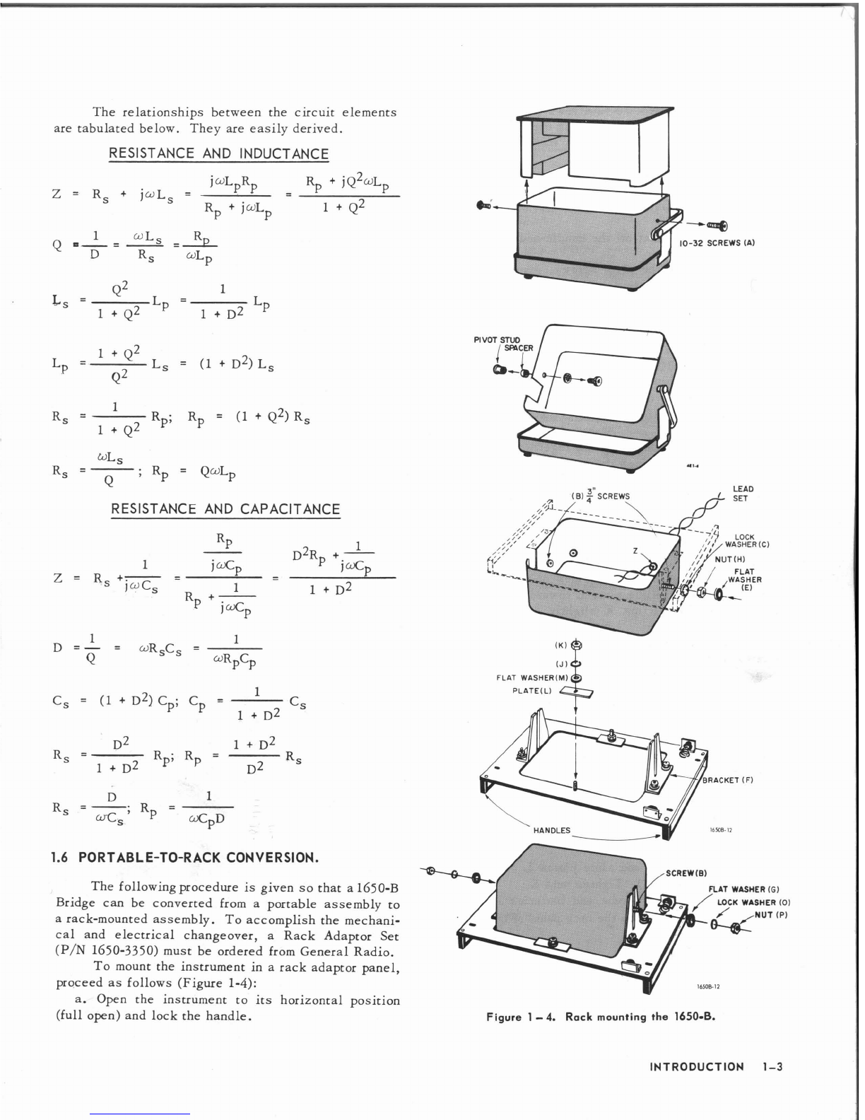
b. Remove the two cabinet screws (Figure 1-4).
c. Lift the instrument from its cabinet.
d. Follow the directions on the battery tube, and
remove the disk.
e. Place the battery tube back in its holder.
f. Replace the instrument in its cabinet.
g. Replace the two cabinet screws.
The instrument
is
now ready to operate as soon as it
is
in the desired position and turned on.
tion manual and for any other test data that should be
kept with the instrument.
Figure
1
-
2.
Type 1650-8 Impedance Bridge
in
rack panel.
INTRODUCTION 1-1

1.4 SYMBOLS, ABBREVIATIONS, AND DEFINITIONS.
R~
G 1
D dissipation factor
=
-
=
-
=
-
=
cot
6'
=
tan
o
The following symbols, abbreviations, and defi-
X
B
Q
nitions are used on the panel of the Type 1650-B and
in this instruction manual: 1
for capacitors wCSRS or
C capacitance
(
++
)
wC~R~
CD external decade capacitor
Co bridge residual capacitance
R R
PF power factor
=
-
=
=
cos
0
R2
+
x2
parallel capacitance
series capacitance
standard capacitor (0.1
@)
unknown capacitance
conductance
(
-
),the inverse of resistance
frequency
angular frequency, 27rf
ohm, a unit of resistance, reactance, or im-
pedance
kilohm,
1
kfl
=
1000 ohms
multiplying factor applied to D and Q at fre-
quencies other than 1 kHz
megohm, 1
MR
=
1
x
lo6
ohms
microfarad, a unit of capacitance
milliohm, lrnn
=
1
x 10-3 ohm
(or mpF) nanofarad (or millimicrofarad), 1nF
=
1mpF
=
1
x pF
unknown conductance
inductance
(
-
)
bridge residual inductance
parallel inductance (or ppF) picofarad (or micromicrofarad), IpF
=
1ppF
=
1
x
IO-~~F
series inductance henry, a unit of inductance
millihenry, 1mH
=
1
x
10-3
H
microhenry,
1
pH
=
1
x
10-6 H
ground, case (chassis)
unknown inductance
resistance
(-),
the realpart of an impedance
ratio arm resistance
standard 10 knresistor
CGRL rheostat resistance
bridge residual resistance
1.5
SERIES AND PARALLEL COMPONENTS.
An impedance that
is
neither a pure reactance nor
a pure resistance may be represented at any specific
frequency by either a series or a parallel combination
of resistance and reactance. Keeping this concept in
mind will be invaluable for properly interpreting the
bridge results. The values of resistance and reactance
used in the equivalent circuit depend on whether a
series or a parallel combination
is
used. The equiva-
lent circuits are shown in Figure 1-3. 'A nomograph
for series-parallel conversion at
1
kHz
is given in the
Appendix.
parallel resistance
series resistance
DQ rheostat resistance
unknown resistance
series reactance, the imaginary part of an
impedance
impedance
XB1
quality factor
=
-
=
-
=
-
=
tan
8
=
cot
6
RGD
for inductors
-
or
-
RS
wLP
Figure
1
-
3.
Equivalent circuits
for
complex impedonce.
INTRODUCTION
1-2

The relationships between the circuit elements
are tabulated below. They are easily derived.
RESISTANCE AND INDUCTANCE
RESISTANCE AND CAPACITANCE
1.6
PORTABLE-TO-RACK CONVERSION.
The following procedure
is
given sothat a 1650-B
Bridge can be converted from a portable assembly to
a rack-mounted assembly. To accomplish the mechani-
cal and electrical changeover, a Rack Adaptor Set
(P/N
1650-3350) must be ordered from General Radio.
To mount the instrument in
a
rack adaptor panel,
proceed as follows (Figure 1-4):
a. Open the instrument to its horizontal position
(full open) and lock the handle.
--@
-32
SCREWS (A)
FLAT WASHERIM)
PLATEIL)
SCREW
(6)
%AT WASHER
(GI
-
/
LOCK WASHER
(0)
Figure
1
-
4.
Rack
mounting the
1650-8.
INTRODUCTION
1-3

b. Remove the No. 10-32 screws
(A)
with resilient
washers that hold the instrument in the cabinet. These
screws are on the sides of the instrument (one per
side) just above the handle pivot.
c. Lift the instrument out of the cabinet and set it
to one side.
d. From the inside of the cabinet, remove the two
pivot screws.
e. Lift the cabinet off the handle-and-cover assem-
bly.
f.
In place of the pivot screws, insert the two
%-
inch screws (B) supplied. Place the lockwasher
(C)
and nut
(H)
on each screw and secure.
g. Remove the eyelet from foot
Z
in the cabinet
(the foot farthest from the side cutout).
h. Remove the rubber foot and install the supplied
grommet (P/N 4110-0500).
i. Set the cabinet to one side.
j.
Remove the battery tube (P/N 1650-1261) from
the instrument by following the instructions on the
tube.
k. Twist the lead-set leads together and feed the
ilnconnected ends through the grommet
(Z)
in the cabi-
net from the outside to the inside.
1. Solder the white lead of the lead set (P/N 1650-
0280) to S103, 204R (Figure 6-9). Solder the black
lead to S102, 204R.
m. Install the instrument in
its
cabinet. Install and
tighten the two No. 10-32 screws (A)removed in step b.
n. Loosen nut K on both sides of the opening in
the rack panel and slide plate L toward the outside of
the panel. Tighten nut K slightly so that L won't
slide
.
o. Put a large flatwasher
(E)
over the projecting
screws on each side of the instrument.
p. Set the back of the instrument on a flat surface
(face upward). Turn the instrument so that it
is
right
side up asyou look at it.
q.
Lower the adaptor panel over the instrument
being sure that the battery mounting brackets are on
the right-hand side. Brackets F go over screws B.
r. Install a flat washer
(G),
lock washer (0) and
nut (P) on screws
B
outside of bracket F.
s.
Raise the adaptor panel up until it
is
flush with
the instrument panel and rubber gasket.
t. Tighten nuts P and turn the instrument over onto
the adaptor handles.
u. Loosen nuts K and slide plates L over the rub-
ber gasket (Figure 1-5). Tighten nuts K.
v. Snap the battery tube and batteries into place
between the insulators on the rack panel (Figure 1-6).
1.7
CONNECTIONS.
The UNKNOWN terminals are standard %-inch-
spaced binding posts that accept banana plugs, stand-
ard telephone tips, alligator clips, crocodile clips,
PANEL
I
L\
CABINET
Figure
1
-
5. Detail
view
of ponel mounting.
LEAD
SET
1650
-
0280
BATTERY
INSULATOR-
(1650-1230)
BATTERY
-
INSULATOR
(1650-
1231)
Battery mounting for rack-mounted 1650-8 Bridge.
INTRODUCTION 1-4

l
nDLC
I
-
I
NOTE:
GR874
connectors are
50
R
and ore rnechan-
ically sexless; i.e., any two, although identical, can
be plugged together.
DESCRIPTION
CATALOG
NO.
274-NQ Double-plug patch cord, in-line cord, 36" long
274-NQM Double-plug patch cord, in-line cord, 24" long
274-NQS Double-plug patch cord, in-line cord, 12" long
274-NP Double-plug patch cord, right-angle cord, 36" long 0274-9880
274-NPM Double-plug patch cord, right-angle cord, 24" long 0274-9892
274-NPS Double-plug patch cord, right-angle cord, 12" long 0274-9852
274-NL Shielded double-plug patch cord, 36" long
274-NLM Shielded double-plug patch cord, 24" long
274-NLS Shielded double-plug patch cord, 12" long
274-LLB Single-plug patch cord, black, 36" long
274-LLR Single-plug patch cord, red, 36" long
274-LMB Single-plug patch cord, black, 24" long
'274-LMR Single-plug patch cord, red, 24" long
274-LSB Single-plug patch cord, black, 12" long
274-LSR Single-plug patch cord, red, 12" long
1560-PY5 Adaptor cable, double-plug to telephone plug, 36" long 1560-9695
874-R34 Coaxial patch cord, double plug to GR874, 36" long 0874-9692
874-R33 Coaxla1 patch cord, two plugs to GR874, 36" long 0874-9690
274-QBJ Adaptor, sh~eldcddouble plug to BNC
Patch cord, shielded double plug to BNC
Patch cord, GR874 to BNC
Patch cord, BNC to BNC
INTRODUCTION
1-5

spade terminals and all wire size up to number eleven
(Figure 1-7).
The EXT DQ, DET, and BIAS jacks accept a
two-terminal telephone plug such as the Switchcraft
No. 440.
The EXT GEN, G, and OPP ARM jacks accept
a single banana plug such as the GR Type 274-DB1
or 2
(P/N
0274-9454 or 9455, respectively). These
jacks are spaced %-inch on centers sothat a GR Type
274-MB Insulated Double Plug (P/N 0274-9875) can
be used between the EXT GEN and G terminals or the
OPP ARM and
G
terminals.
General Radio also makes a variety of intercon-
necting cables that can be used in various system
interconnections. Some of these cables are shown in
Table 1-1.
Figure
1-7.
Methods
of
connection to the measurement terminals.
Clamps
up
to
No.
1
l
INTRODUCTION
1-6

Section
2
-
Basic Measurements
2.1
GENERAL.
Figure 2-1 shows the six bridge circuits used
in the Type 1650-B Impedance Bridge, as well as the
balance equations. Hays and Maxwell inductance
bridges and series and parallel capacitance comparison
bridges are used to provide wide coverage over the
D
and Q ranges. Full use of these wide ranges at low
Q
and high
D
values
is
achieved by means of an Ortho-
null@balancing mechanism (paragraph
5.4).
Both ac
and dc measurements may be made with the bridge,
which has a magnitude responsive detector.
The next two pages concisely state the informa-
tion needed for making basic measurements. The
schematics include allrelevent bridge terminals to aid
the user in making special measurements that require
bias, etc. The symbols on the diagrams are the same
as those defined in Section
1.
A
short discussion of
Orthonull usage, detector sensitivity, etc relating to
basic measurement practice follows the instruction
chart.
Cs
c~
R
(
Y,"ODI)
(07';:
tgH0)
(3
SERIES CAPACIJANCE PARALLEL CAPACITANCE RESISTANCE
UNKNOWN
~n
TO
lMeg
ao"
R~ R~
ICGRL"
0-16k
c
r
Dluf
RATIO
0-Ilk
RATIO
10
k
0-Nk
L~
L~
(
LOW
O
:
02 TO10
SERIES INDUCTANCE PARALLEL INDUCTANCE
Figure
2-
1.
Bridge circuits used in impedance bridge.
BASIC MEASUREMENTS
2-1

I
i
i
*-
LOW
D
10 TO
I1
%y
...
cxpKj
o
UNKNOWNHIGH
&As
opt-
T,?
TIP+
BODY
ARM
'"
Do0\
(1
hn
cGRL
RHEOSTAT
01pF
CASE
c,
;
c,
b,O
<
Dx
UR~C~
vRTCT
a.
Turn GENERATOR switch to
BAT CHECK position. If the meter
pointer is not in the BAT sector,
replace the batteries.
b. Turn GENERATOR switch to AC
EXTERNAL or AC
INTERNAL
1 kHz.
c.
Turn PARAMETER switch to Cs.
d.
Connect the unknown so that
most stray capacitance is between
the LOW terminal and the
1650-8
case.
e.
Turn
ORTHONULL@
switch to
OUT.
f.
Turn OSC LEVEL clockwise.
The panel control affects only the
internal oscillator.
g.
Turn DQ dial near 0.05 on the
LOW
D
scale.
h.
Turn CGRL dial near
11.
i.
Adiust DET SENS for about
6
divisions deflection.
i.
Turn MULTIPLIER switch for
minimum meter reading.
k.
Alternately adiust, firstthe CGRL
dial, then the DQ dial for the best
null, increasing the DET SENS as
needed.
I,
ORTHONULL@
is not used on
thisbridge unless the DQ dial read-
ing times f(kHz) approaches or ex-
ceeds 1.
m.
If the DQ dial goes into the
uncalibrated portion, the unknown
should be measured as
Cp.
n.
The series capacitance of the
unknown equals the product of the
CGRL-dial reading and the
MUL-
TIPLIER-switch setting.
o,The D equals the reading on the
DQ dial times f (kHz).
p.
Turn GENERATOR switchtoOFF.
HIGH
0
(0
I
TO 50)
O
l
iF
C,
$CT
6-
8
DL-
'
"RXCX
vRTC,
a.
Turn GENERATOR switch to
BAT
CHECK position.
If
the meter
pointer is not in the BAT sector,
replace
the batteries.
-rum
GENERATOR
switch
to
AC
EXTERNAL or AC INTERNAL
1
kHz.
c.
Turn PARAMETER switch to Cp.
Large electrolytics should be mea-
sured at a low frequency (120 Hz)
for greater accuracy.
d.
Connect the unknown so that
most stray capacitance is between
the LOW terminal and the 1650-8
case.
e.
Turn
ORTHONULL@
switch to
OUT.
f.
Turn OSC LEVEL clockwise.
The panel control affects only the
internal oscillator.
g.
Turn DQ dial near
0.2
on the
HIGH
D
scale.
h.
Turn CGRL dial near 11.
i.
Adiust DET SENS for about
6
divisions deflection.
i.
Turn MULTIPLIER switch for
minimum meter reading.
k.
Alternately adiust, first the DQ
dial, then the CGRL dial for the
best null, increasing the DET
SENS
as needed.
I.
ORTHONULL@
switch should be
set to IN if the DQ dial reading
times l/f (kHz) approaches or ex-
ceeds 1.
m.
If
the DQ dial reaches the stop
at 0.1, the unknown should be mea-
sured as Cs.
n.
The parallel capacitance of the
unknown equals the product of the
,
CGRL-dial reading and the MUL-
TIPLIER-switch setting.
o. The D equals the reading on the
DQ
dial times
l/f
(kHz).
p.
Turn GENERATOR switch OFF.
--
R
IN. OC
e-o
UNKNOWN
o
HIGH
loon
+
6
VOLTS
(1
ARMopp
RHEosTaT
cGRL
(ti 10
kn
a,#
E
ExT
oc
cbsc
Rrxr
21~1~
,$,
VOLT&dE
@=
E;
UNKNOWN
o
HIGH
T,P*
BlbS
OPP
BWI
50kn
ARM
CGRL
(#in
RHEOSTAT
10
kn
a=
w
CLIE
Ac
1::~~~
UNKNOWN
o
HIGH
BOD"
-
ARMopp
CGRL
'Ihn
RHEOSTAT
10
kn
a%L
R*R~
a,&
0
Rx
7
a.
Check mechanical zero of meter.
b. Turn GENERATOR switch to the
BAT CHECK position. If the meter
pointer is not in the BAT sector,
replace the batteries.
c.
Turn GENERATOR switch to the
desired generator source. The
OSC
LEVEL control affects only the
internal osci
l
lator.
d.
Turn
ORTHONULL@
switch to
OUT and PARAMETER switch toR.
e. Turn CGRL dial near
11.
f.
Adiust DET SENS control for
about
6
divisions deflection.
g. Turn MULTIPLIER switch for
minimum reading to the left of
center
if
making a dc measurement.
Null as usual if making an ac mea-
surement. (DQ rheostat not in the
circuit.)
h.
Adjust CGRL dial for best ac
null, or zero the pointer
if
using
dc.
If
ac null is not sharp, a re-
active balance may be necessary,
see instruction manual.
i.
The unknown resistance is the
CGRL-dial reading multiplied by
the MULTIPLIER switch setting.
i.
Turn GENERATOR switch to
OFF.

OPERATING INSTRUCTIONS
MULT
RAR
H
1
I0 100.
10k lOOk 1M
MULT
RAR
nU
100
1M
HIGH
o
(I
m)
0
R'-
"LX uRTCT
a. Turn GENERATOR switch to
BAT CHECK.
If
the meter pointer
isn't in the BAT sector, replace
the batteries.
b.
Turn GENERATOR switch to AC
EXTERNAL or AC INTERNAL
1 kHz.
c.
TurnPARAMETER switch to
Lp.
d.
Connect unknown so that most
stray capacitance is between the
LOW terminal and the 1650-B case.
e. Turn ORTHONULL@ switch to
OUT.
f.
Turn OSC LEVEL clockwise.
The panel control affects only the
internal oscil[ator. Use full output
except for nonlinear unknowns.
Iron core inductors are often non-
I
near.
'
g. Turn DQ dial near
5
on the HIGH
Q scale.
h.
Turn CGRL dial near 11.
i.
Adiust DET SENS for about
6
divisions deflection.
i.
Turn MULTIPLIER switch for
minimum meter reading.
k.
Alternately adiust the CGRL and
DQ dials for the best null, CGRL
first, increasing the DET SENS as
needed. Null means bring the
pointer as near to the center of the
meter as possible. Usually it won't
be possible to center the pointer.
I.
ORTHONULL@
is not used on
this bridge unless the DQ dial
reading times l/f (kHz) approaches
1 or less.
m.
If a sharp nu1
l
cannot be ob-
tained, the unknown is too lossy
and must be measured as
Ls,
or
the unknown is not inductive.
n.
The ~arallelinductance of the
unknown equals the product of the
CGRL-dial reading and the MULTI-
PLIER-switch setting.
o.
The Q of the unknown equals the
dial reading times l/f (kHz).
p.
Turn GENERATOR switch to
OFF.
G
RESISTANCE
cln
m
1ooo~n1
INT
DC
UNKNOWN
0
HlGH
6
VOLTS
OPP
ARM
llhn
CGRL
0
*n
RHEOSTAT
,.m>'
CllL
EYT DC
REXT
Z~VI'
@zv::
UNKNOWN
HlGH
BIAS
OPP
MD"
5o*n
ARM
I0
MI
'I*
CGRL
RHEOSTAT
AX
CASE
Ac
nlri
a. Check mechanical zero of meter.
b.
Turn GENERATOR switch to the
BAT CHECK position. If the meter
pointer is not in the BAT sector,
replace the batteries.
c. Turn GENERATOR switch to the
desired generator source. The OSC
LEVEL control affects only the in-
ternal oscillator.
d.
Turn
ORTHONULL@
switch to
OUT and PARAMETER switch toG.
e. Turn CGRL dial near 11.
f.
Adiust DET SENS control for
about 6 divisions deflection.
g.
Turn MULTIPLIER switch for
minimum readingto the left of center
if making a dc measurement. Null
as usual if making an ac measure-
ment. (DQrheostat not inthe circuit.)
h.
Adiust CGRL dial for best ac
null, or zero the pointer if using dc,
If ac null is not sharp, a reactive
balance may be necessary, see
instruction manua
I.
i.
The unknown conductance is the
CGRL-dial reading multiplied by
the MULTIPLIER switch setting.
i.
Turn GENERATOR switch to
OFF.
i"H
I00
1
iiiu
1
10 100
lOOk lOk lk
mH
1
I0 I00
10 100 Ik
Ls
-
LOW
o
(002
TO
10)
L~
'LRdiC,
Q
"'X
YRTCT
RX
mU
1
10 100
100 10
1
1
1ok 10look
H
1001M
MuLT
RA~
a. Turn GENERATOR switch to
BAT CHECK. If the meter pointer
isn't in the BAT sector, replace
the batteries.
b.
Turn GENERATOR switch to AC
EXTERNAL or AC INTERNAL
1 kHz. Air core rf chokes should
be measured at a high frequency
(10 kHz) to get a reasonable Q.
c.
Turn PARAMETER switch to
Ls.
d.
Connect unknown so that most
stray capacitance is between the
LOW terminal and the 1650-B case.
e* Turn ORTHONULL@ switch
to
OUT.
f.
Turn OSC LEVEL clockwise.
The
ane el
control affects only the
internal oscillator. Use full output
except for nonlinear unknowns.
Iron core inductors are often non-
I
rnear.
'
g. Turn DQ dial near
4
on the LOW
Q scale.
h.
Turn CGRL dial near 11.
i.
Adjust DET SENS for about 6
divisions deflection.
i.
Turn MULTIPLIER switch for
minimum meter reading.
k.
Alternately adiust the CGRL and
DQ dials for the best null, DQ dial
first, increasing the DET SENS as
needed. Null means bring the point-
er as near to the center of the
meter as possible. Usually
it
won't
be ~ossibleto center the pointer.
I.
ORTHONULL@
should be switch-
ed IN if the DQ-dial reading times
f (kHz)approaches or is less than 1.
m.
If a sharp null cannot be ob-
tained and the Q dial is near 10,
switch to
L
17'
n.
The serles inductance of the
unknown equals the ~roductof the
CGRL-dial reading and the MULTI-
PLIER-switch setting.
0.
The Q of the unknown equals the
Q-dial reading times
f
(kHz).
p.
Turn GENERATOR switch OFF.
loo
PH
1
1
lo
10
loo
mH
loo
Ik

2.2
DC AND AC SENSITIVITY.
With the internal 6-volt supply, one-percent bal-
ances may be easily made up to 10kR and with care
up to 100kR. Above 100kR a higher external voltage
should be used (paragraph 3.2). Below
ln,
the sensi-
tivity limits the accuracy to fl~mR.A more sensitive
meter may be placed in series with the internal meter
by plugging it into the BIAS jack on the side of the
bridge.
A 100-a resistor in series with the internal 6-V
supply limits the current in the unknown to 60 mA.
The unknown
is
in series with the CGRL rheostat for
external dc, so that the unknown current
is
greatest
when the CGRL dial
is
at zero.
The maximum power that can be applied to the
bridge by the internal supply
is
0.09W; thus there
is
nodanger of injuring components rated at 0.1W or more.
At range extremes
it
is
often desirable to make
1-kHz ac measurements to increase sensitivity. For
most resistors, the difference between the measured
1-kHz and dc values
is
negligible.
An external tuned null detector, such as the
1232,
is
very desirable when making measurements
at frequencies other than 1kHz. It may be connected
between the LOW UNKNOWN terminal and the 1650-B
case. The screw near the UNKNOWN binding post is
a convenient ground point.
t
I
HELL
L-
l
2
MAXIMUM DCBRIDGEVOLTAGE
AND CURRENT
2.3
DC VOLTAGE AND CURRENT LIMITS.
WARNING
Bridge voltages must be limited to pro-
tect the bridge and the unknown com-
ponent from damage. It
is
also advis-
able to limit the current to 5 mA or less
to protect the operator from injury. The
maximum voltage limit, standard EIA
test voltages and some military test
voltages
are
described below.
I* Max
100mA
100
m~
71
mA
22
mA
14.1
mA
14.1
mA
14.1
mA
Unless the utmost in sensitivity or
a
standard
test voltage
is
desired,
a
supply of about 100 V (e.g.,
a
90-V battery), with about 25 kain series,
is
recom-
E
Max
71V
71
v
71 V
71 V
71 V
223 V
500V
Range
Full Scale
1
R
IO~
10Ofl
I
kn
10
kn
100
kn
1
MR
Range
Multiplier
100
rnn
~n
100
100R
I
kfl
10
kn
100
kn
REC
117
appliesonly up to
9999R.
*
itis preferable to limit current to avold shock
*
At
EXTGEN
terminals.
hazard or to reducevoltage to
10V.
**
Maximum allowance bridgevoltagewill not give maximum
test voltage.
1
HDLC
L-L
EIASTANDARD TEST VOLTAGES
(RS
196
FIXED-FILM RESISTORS
REC 117 LOW-POWER WIRE-WOUND RESISTORS)
*
at
EXTGEN
terminals
**
cannot get required bridge voltage
***
limited to
71 V
by bridge
Resistance
Range
less than
10
10-99R
100
-
999R
1000
-
9999R
10-99
kR
100
kfl
up
1
HDLC
L-J
EIASTANDARDTEST VOLTAGES
(RS 172
-
FIXED COMPOSITION ,RESISTORS)
BASIC MEASUREMENTS
2-4
EIA Max
Test Voltage
0.3 V
1
V
3 V
10
v
30 V
100 V
Bridge Mult
Range
1
a
100
100
R
I
kR
10
kR
100
kR
Max Fridge
Voltage
+
*I
**
33 V
20
v
33 V
101 V
Resistance Range
2.7
-
99
n
100
-999R
1000
-
99990
10
-99kR
100
kn
up
voltageEIA Test
R~~~~
0.5-
I
v
0.5- 1 V
2.5- 3 V
8 -lOV
24 -3OV
80 -lOOV
Bridge
Muit
Range
in
10
R
I
00
0
I
kR
I0
kR
100
kR
Bridge*
Voltage
**
50
-
71 V***
27.5
-
33 V
16 -2OV
26.4
-
33 V
80
-
IOOV

r
TABLE
2-4
VARIABLE RESISTORS
(Military Specifications)
Spec. Title
&
Date Resistance Measurement Accuracy Test
Description Tolerance (all Meas. at dc). Voltage
Mi
I-R-94B
7130157 f10
&
20%
Qualification inspection: Table
2-6
Amend. No.
2 2/27/62
not to exceed
L0.5%
ResistorsVariable Acceptance inspection:
Composition
-
continuous
f
1%
operation when properly
derated, at any a'mbient GR Bridges: Qualification:
temp. up to
120
C
1608
and
1652
GR BridgesAcceptance:
1608, 1650,
&
1652
Mil-R-22097B
5114/62 &lo% L1.0%
Table
2-5
Lead-screw-actuated
NonwirewoundVariable
G
R Bridges:
1608, 1652,
&
-at
maxi mu^
ambient
1650
temps. of
70
C,
85'
C,
&
125O
C.
Mil-R-23285A
1
1118/65 k5
&
10%
Qualification inspection: Table
2-7
Nonwirewound Metal
f0.5%
Film Variable
-
Quality conformance:
fl%
continuous full rated
load operation at an GR Bridges Qualification:
ambient temp. of
1608
&
1652
125'
C.
G
R
BridgesConformance:
1608, 1652, 1650
Mil-R-19A
11/9/56
f
10%
f
1.O%
As small as
Amend. No.
2 1/6/59
practical
Low Operating Temp.
G
R Bridges:
1608, 1652,
&
Wirewound Variable;
1650
ambient tEmp. of
40
C
up to
105
C.
Mil-R-22B
3/21/62 f10%
f
1.0%
As small as
Power Type Wirewound
G
R Bridges:
1608, 1652,
&
practical
Variable
1650
I
TABLE 2-5*
MIL-R-22097BTEST VOLTAGES
TABLE 2-6
MIL-R-94BTEST VOLTAGES
100
to
999 .O1
to
2
1
k to
9.99 k 0.1
to
4
10 k
to
99.99 k 1.0
to
15
100
k
Iln
Test Voltage (V)
Resistor Range (0) (DO NOT EXCEED)
less than
1
1
to
9.99
10
to
99.9
100
to
999
1
k
to
9.99
k
10k
to
99.9 k
100k
up
BASIC MEASUREMENTS
2-5
0.1
0.3
1
.o
3.0
10
30
1
00
1
ABLt
2-/
MIL-R-23285ATEST VOLTAGES
*
0.5
W and larger resistors.
Resistor Range
(a)
2.7
to
99
100
to
990
I
k
to
9.9 k
10k
to99
k
100 k
or higher
Voltage Range (V)
0.3
to
0.5
0.5
to
1.5
1.5
to
4.5
4.5
to
15
15
to
45

mended. The available power from such a supply
is
0.1 W, which is a low enough dissipation for almost
all resistors, and the maximum current is 4 mA. Such
a supply permits measurements up to
1
MO
with 1%ac-
curacy. For resistance over
1
MR,
a higher voltage is
desirable for good sensitivity, but it should be noted
that the maximum EIA test voltage
is
100
V,
and that
various types of resistorshave different voltageratings.
The maximum voltage and current that may be
applied to the bridge for each range are given in Table
2-1. Careful observation of both of these limits will
prevent damage to the bridge.
Because the full voltage may be applied to the
unknown, it
is
advisable to limit the available power
to a value less than the power rating of the unknown
component.
CURRENT-LIMITINO
RESISTOR
Figure
2
-
2.
Circuit for standard
test voltage measurements.
Various EIA standards for testing different
types of resistors are summarized
ii
Tables 2-2 and
2-3. Various military standards are listed in Tables
2-4 through
2-7.
A suggested setup for tests at these
voltages is shown in Figure 2-2. The voltmeter here
indicates the bridge voltage and should be set as listed
in Tables 2-2 and 2-3. An alternate scheme is to put
the voltmeter directly across the unknown resistor,
assuming that the input resistance of the voltmeter
is
large enough to cause no error.
2.4
CONNECTION OF EXTERNAL GENERATOR.
In most cases when an external generator is used
it should be connected to the EXT GEN jack on the
side of the bridge. In this connection, the external
generator is connected directly to the internal bridge
transformer when the function switch
is
in the AC EX-
TERNAL position, and the low generator terminal is
connected to the bridge chassis (which should be
grounded; paragraph 4.6). A second ground connection
to the generator should be avoided.
If the external generator can be overdriven when
connected to a low-impedance load, it is generally de-
sirable toplace a resistor in series with the ungrounded
generator connection to the bridge. This resistor
should be large enough to prevent distortion even when
the bridge input is short-circuited. The bridge input
impedance at the EXT GEN jack is a minimum of 30
fl
(resistive) at 1 kHz when the bridge is set to measure
a short circuit on the UNKNOWN terminals. This is
shunted by the inductance of the primary of the bridge
transformer, which is approximately 0.25
13.
In some cases where more input power
is
re-
quired, particularly in measurements of low impedance,
a matching transformer between generator and bridge is
useful. This transformer need not be shielded. The
GR Type 1311 Audio Oscillator
is
recommended for
this application at frequencies of 50,
60,
100, 120,
400, 500, 1000, 2000, 5000, and 10,000 Hz because its
output will not be distorted by over-loading and it has
a matching transformer to drive low-impedance loads.
When the desired bridge voltage is higher than
can be applied by the internal bridge transformer, the
generator can be connected directly in the bridge cir-
cuit by connection to the BIAS jack (Figure 2-3a). In
this connection, the generator is ungrounded and ca-
pacitance from its terminals to ground must be con-
sidered. Capacitance from the negative BIAS terminal
to ground can cause a large error at high frequencies
when low impedances are measured. Therefore, use a
shielded cable and use the outer conductor to connect
the low generator terminal to the positive BIAS termi-
nal. Capacitance of over 100 pF from the positive
BIAS terminal to ground can cause appreciable error
(paragraph 4.6). A bridge transformer can be used to
connect a generator to the BIAS jack, but this has no
advantage over the use of the internal bridge transform-
er unless the external transformer has a higher voltage
rating, as do the GR Type
578
Transformers (Figure
2-3b).
SHIELDED BRIDGE-TF~NSFORMER
OSC
Figure
2
-
3.
Methods of applying external ac.
2,s
MAXIMUM APPLIED AC VOLTAGE.
The maximum ac voltage that may be applied to
the 1650-B Impedance Bridge depends on:
a. the voltage and power ratings of each compon-
ent (including the unknown),
b. the bridge circuit used,
c.. the range used,
d. the position of the variable components,
e. the method of applying the voltage.
Exact limits for any specific measurement can be cal-
culated from the circuit diagrams of Figure 2-1, and by
insuring that the power dissipation in the ratio-arm
BASIC MEASUREMENTS
2-6

resistors and the rheostats is less than 0.5
W.
If such
a maximum voltage
is
applied, care must be taken to
avoid any adjustments of the panel controls that would
result in an overload.
A much simpler approach
is
to limit the power
into the bridge to 0.5
W
so that no bridge components
can be damaged under any conditions. If the power
rating of the unknown is less than 0.5 W, the input
power should be reduced accordingly. A series resistor
is
the simplest way to limit the power. It should have
E
a value of R
=-
where
E
is
the open-circuit genera-
4P
'
tor voltage and P the power rating of the unknown com-
ponent.
The input transformer imposes the following fur-
ther limit on the voltage applied to the EXT GEN jack:
-
f
Emax
--
volts (f in Hz), or 100 volts,
5
whichever is smaller. This transformer has a 3-to-1
step-down ratio and an equivalent resistance, referred
to the primary, of 20
0.
Therefore, to limit the power
applied to the bridge to 0.5 W, a series resistor of
2
&-
-
200 should be placed in series with the external
2
supply.
2.6
OPERATING PROCEDURE WITH ORTHONULL.
In the measurement of inductors whose Q
is
less
than
1
or capacitors whose D
is
greater than 1, bal-
ancing procedure can be simplified and false nulls
avoided by the use of Orthonull. It should be noted
that Orthonull operates on all four bridges (Cs, Cp,
Ls,
L
)
and at any frequency. It will facilitate the balance
wbn the unknown
is
very lossy, i.e., has a high D or
a low Q at the frequency of measurement. The white
sectors of the DQ dial are adjusted for IkHz. At other
frequencies they don't apply. The balancing procedure
(essentially the same as without Orthonull once the
Orthonull mechanism is engaged)
is
asfollows:
a. Set the bridge switches as described in the
Operating Procedure Chart, depending on what
is
being
measured. Connect the unknown to the UNKNOWN
terminals and connect the external generator (if one
is
used)
as
described in paragraph 2.4.
b. Set the ORTHONULL SWITCH toIN.
c. Set the CGRL dial upscale (10 or 11).
d. Make the first balance with the DQ dial.
e. Adjust the CGRL dial for further balance (the
DQ dial, ganged to the CGRL dial by the Orthonull
mechanism, will follow). If the CGRL setting
is
less
than
1
at balance, turn the CGRL MULTIPLIER switch
to a lower range and rebalance.
f. Make further balances using first the DQ dial,
then the CGRL dial, then the DQ dial, etc. until the
meter reading cannot be reduced further.
When the Q
is
very low, the meter deflection will
give several sharp dips as the CGRL dial
is
rotated.
To find the best dip, rotate the CGRL dial slowly over
a wide range without making another DQ adjustment.
Often the Q
is
higher at some other frequency,
and it
is
desirable to change the frequency of meas-
urement. This
is
necessary if the inductor
is
above
resonance and appears capacitive. A DQ Coverage
Chart
is
shown in Figure
2-4.
Figure
2
-
4.
DQ
coverage chart.
BASIC MEASUREMENTS
2-7

Section
3
-Special Measurements
3.1
GENERAL.
The inclusion of the
EXT
DQ,
BIAS,
and
OPP
ARM
jacks in the 1650-B permits many special meas-
urements to be made. The EXT DQ jack allows ex-
tension of the DQ coverage at frequencies below 100
Hz,
the
BIAS
jack allows a bias voltage or current to
be applied across or through an unknown impedance,
and the
OPP
ARM
jack allows more accurate balancing
of reactive resistors. The following section presents
a few of the many applications possible with these
external connection jacks.
3.2
APPLICATION OF DC BIAS TO CAPACITORS.
3.2.1
INTERNAL OSCILLATOR OPERATION.
Up to 600
V
of dc bias may be applied to the un-
known capacitor by any of several different methods.
r)
DET
p
DET
The simplest method can be used for measuring only
series capacitance; fortunately, this
is
how most ca-
pacitors are specified.
WARNING
Charged capacitors form a shock hazard,
and care should be taken
to
ensure per-
sonal safety during measurement and to
be sure that the capacitors
are
dis-
charged after measurement. The exter-
nal dc
supply
should also be handled
carefully.
It
is
advisable to limit the power that may be
drawn from the external dc supply to 0.5
W
(by a resis-
tor, fuse, or circuit breaker) in order to protect the
bridge components in case the unknown
is
short-cir-
cuited.
DDET
Figure 3-
1.
Methods of applying dc voltages to copacitance.
SPECIAL MEASUREMENTS 3-1

The various methods of applying dc bias to ca-
pacitors and suggestions for their use are described
in the three methods that follow:
Method
1.
CS
Bridge (Figure
3-la).
In this method, up to 600
V
may be applied on
any range. Connect the negative terminal of the un-
known capacitor (if polarized) to the
LOW UNKNOWN
terminal. The dc supply used should have a low ac
output impedance. It
is
usually helpful to ground the
negative side of the dc supply and to leave the bridge
floating to avoid hum from the power line. If the nega-
tive side of the supply (BIAS jack body)
is
grounded,
the bridge panel and
LOW UNKNOWN
terminal will be
at low dc potential with low signal voltage on them.
Method
2.
Cp Bridge (Figure
3-lb).
The same precautions mentioned in Method
1
ap-
ply here, and a blocking capacitor should be added
using the EXT DQ jack. The positive side of the
blocking capacitor should be tied to the tip of the
phone plug. The voltage rating of this capacitor should
be sufficient for the full dc applied. The capacitance
required depends on the D of the unknown and on the
accuracy required. The errors caused by this capacitor
are:
n
Lt
C measured
=
Cx (1
-
D~
)
where Cr
=
0.1 /uf
5
and
C,,
>>
C
D
measured Dx (1
+_
DI)
Method
3.
Csor Cp Bridge (Figure
3-lc
and
e).
This method
is
recommended for small capaci-
tors. The maximum voltages that may be applied to
the Cs and Cp bridge are given in Table 3-1, but the
maximum voltage on the bridge are a function of the
CGRL-and-DQdial settings.
The ac impedance of the dc source should be
high (>10kR) to avoid shunting the detector, and the
dc source should have low hum. The advantages of
this circuit are that the bridge and supply are both
grounded and the dc current can be easily limited by
a
resistor, since the impedance of the source should be
high.
WARNING
Note that
the
LOW UNKNOWN terminal
hasthe highvoltageon it in this method.
3.2.2
EXTERNAL AC GENERATOR OPERATION.
When both external ac and dc supplies are used,
hum may be introduced by the capacitance to the line
in the power transformers of these generators. The
bridge should be set up as shown in Figure 3-1, with
both the ac and dc supplies grounded and the bridge
not grounded. The ac generator should be shunted by
a resistor
if
it does not provide
a
path for dc.
Method 3, paragraph 3.2.1, may also be used to
apply dc bias. The bridge and both the ac and dc sup-
plies are grounded (Figure 3-l), and the ac generator
is
connected to the EXT
GEN
jacks. This method
is
particularly useful for high-frequency measurements of
small capacitors (paragraphs 2.4 and 3.2.1).
TABLE
3-1
MAXIMUM DCVOLTAGES APPLlED
TO CAPACITORS
BY METHOD
3
3.3
APPLICATION OF DC TO INDUCTORS.
Range
Multiplier
100
pF
1
nF
10
nF
100
nF
1
PF
10
pF
100,uF
Direct current may be supplied to inductors dur-
ing measurement by any of several different methods
so that incremental inductance measurements may be
made. The various methods are described below along
with suggestions for their use. A blocking capacitor
(Cb in Figure 3-2) is needed only for the Ls bridge
shown. This capacitor (not supplied with the bridge)
should be connected by a phone plug inserted into the
EXT DQ jack. The errors caused by this capacitor are:
To get the corrected results add(%)(A)to the
Qx
Max Volts
On
Bridge
505
V
242
V
142
V
78
V
72
V
71
V
71
V
measured
Ls
and
Q.
It will be necessary to solve for
Qx in equation (2) but usually Qmeas
ured
2:
QX.
Max Volts
On Unknown
500
V
220
V
71
V
7
V
0.7
V
0.07
V
0.007
V
WARNING
Large inductors carrying high currents
are shock hazards. Reduce the dc to
zero before disconnecting the dc supply
or unknown inductor.
SPECIAL MEASUREMENTS
3-2
Table of contents
Other GENERAL RADIO COMPANY Media Converter manuals