Genesys EXPO 4 User manual

Rubber Mallet, Flat Head Screw Driver
Expo Spanner (included), Spanner 8mm
Tools Required
Two competent people wearing safety gloves,
safety shoes and protective eyeware
are recommended to undertake the assembly.
Safety Precaution
1 2 3 4 5 6
7
700
1000
1150
Width
(mm)
Depth (mm)
Expo 4 Shelf Capacities
140kg
300
110kg
90kg
130kg
400
200kg
180kg
200kg
500
180kg
150kg
180kg
600
200kg
150kg
1. Attach plastic feet to the uprights
2. Attach the horizontal battens to join the uprights together
and push lug in using the flathead screwdriver, repeat for
the second frame.
3. Insert shelf clips at desired heights to position the
shelves.
4. Place top and bottom shelves onto the clips.
5. Attach the cross bracing at the back of the bay using the
expo spanner + 8mm spanner.
6. Insert the remaining shelves onto the shelf clips to
complete the bay.
7. To add an extension bay, repeat steps 1, 2 and 3 for one
frame, insert shelf clips at the desired height into the
outside of the existing bay. Repeat steps 4 and 6.
EXPO 4 Assembly Instructions

Expo H Bracing Installation
H Brace is used instead of the standard Cross Brace on both
Expo 3 or Expo 4 bays to allow access from all sides. The
standard Cross Brace ‘obstructs’ the back of the bay so loading
is only possible from the front (and sides), while the H brace,
attached at the shelf level, allows access from both the front and
back (and sides) of the bay.
1. Build the first Expo bay and also install all shelves at desired
heights as per the original Expo Assembly Instructions - excluding
the Cross Brace installation step. The bay should be supported
by another person or leaned against a wall while building it.
2. Install first H Brace to the front of the bay at the height of the
second shelf from the bottom. Use the M6x15 nuts and bolts to fix
the H brace to the uprights - locate the right 2 holes on the H
Brace matching the holes on the uprights - depending on the
shelf height, they might be at a different position. One hole should
be above the shef level and the other below the shelf level.
3.Intall the second H brace to the back of the bay, the same way
as the first one, but position it to the second shelf from top of the
bay.
If you are building a run of Expo bays, please refer to the bracing
diagram below. To see how to build a run of Expo bays, please
refer to the original Assembly Instructions that came with your
particular Expo system.
2 31
Top View
Upright
H Brace Bolt
Nut
Bracing Diagram for a run of Expo bays using H Braces
Picture above shows how the position for bolts might differ
depending on the shelf position.(example only)
Expo Spanner (included)
Tools Required
EXPO - ‘H’ BRACE Assembly Instructions

123
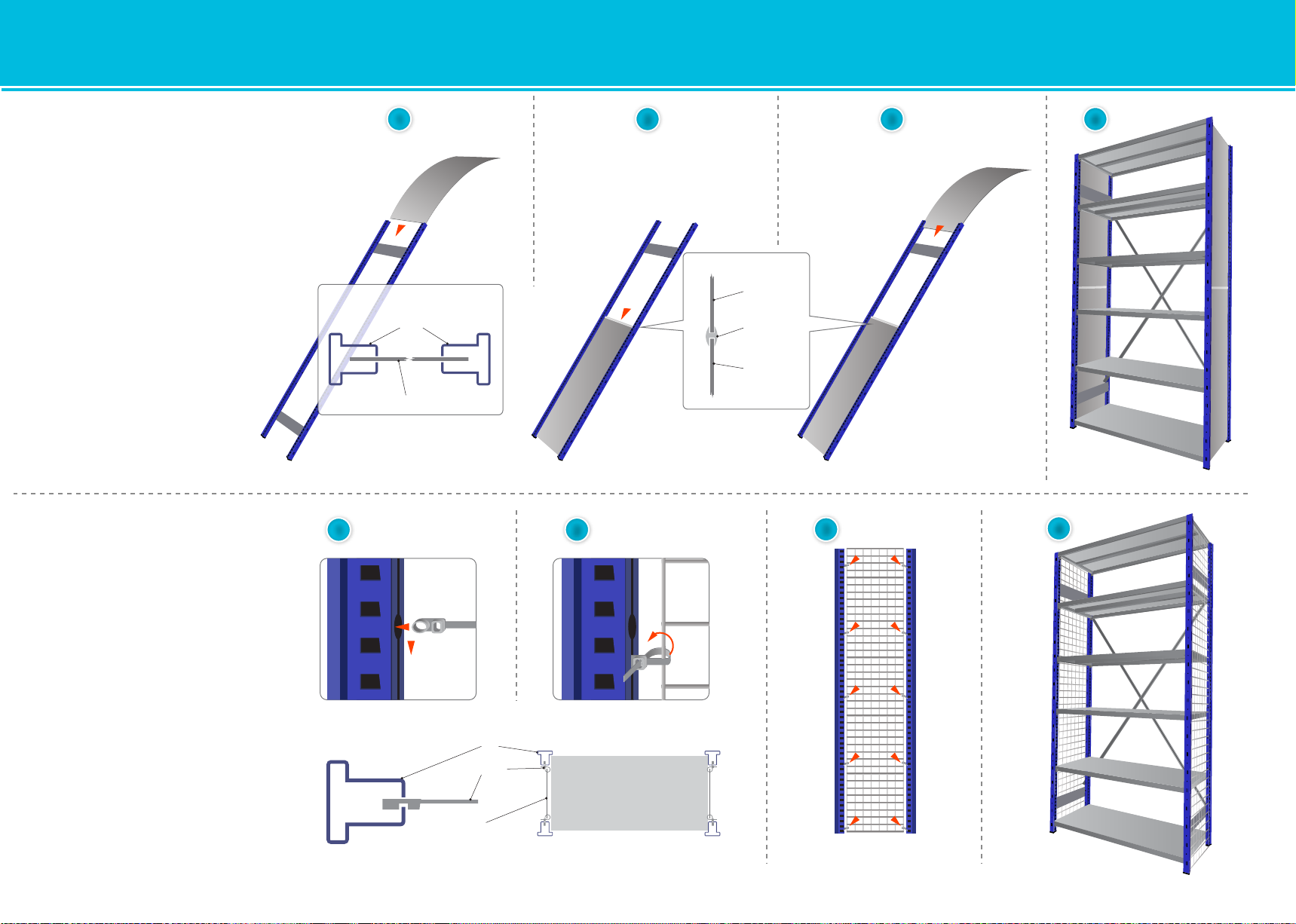
Back Mesh Panel Installation
Mesh back panels can be attached at any time
after the bay has been assembled.
1. Push the arrow tip of the cable tie through the
hole on the back of the upright.
2. Position the mesh as required and loop the tie
around the outer wire of the mesh.
3. Repeat the process along the whole height of
the bay and on both sides of the mesh. Use as
many ties as required - approx 2-3 ties per meter
per side. To cover the whole back of the bay, you
will need to use 2 or more mesh panels and use
basic cable ties to join the panels together.
4. To prevent goods falling off at the back behind
the shelf and the mesh, push the black clip onto
the edge of the shelf and run through another
cable tie to connect the clip and the back mesh.
Use the clip on every 2nd shelf.
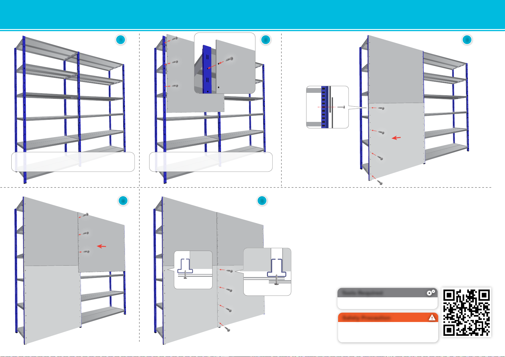
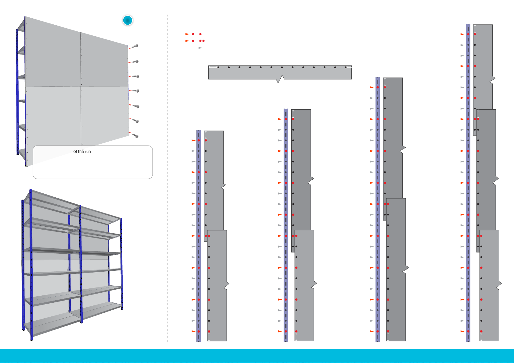
Hook-in Back Cladding Installation
Depending on the height of the bay, use a
combination of 400 and 500 mm tall panels.
Do not use any bracing on bays with hook-in back
cladding.
1. Place the first back cladding pannel to the back
of the bay by inserting the hooks on the panel to
the vertical slots at the back of each upright.The
first panel is situated 100mm off the floor.
2. Continue placing the other panels from the
bottom up, on top of each other.
3. Insert the U Clip to both uprights just above the
top hook of the top back panel to prevent the
panels being accidentally knocked out.
2
4
Uprights
Cable Ties Back Mesh Panel
Shelf
Back Mesh Panel
Shelf
Clip
Cable Tie
1
U Clip
3
100mm
EXPO BACK CLADDING Assembly Instructions

Side Cladding Installation 1
1
2
2
3
3
Side Cladding is installed in the first part of the
bay assembly, when two uprights are connected
either by battens (expo 4) or shelf carriers (expo3)
with feet attached - so you have completed step 2
on the bay assembly instructions.
1. Lean the connected frame to the side and slide
in the first steel sheet clad in between the uprights
inner gaps.
2. Attach plastic joining rib to the top of the first
steel sheet clad.
3. Slide in another steel sheet clad panel the
same way as the first one to sit in the ridge of the
joining rib.
4. Once all frames requiring side cladding are
assembled, continue building the bay as
described on the bay assembly instructions
- step 3 and onwards.
Mesh Side Panel Installation
Mesh Side panels can be attached at any time
after the bay has been assembled.
1. Insert the Cable tie into the upright’s inner gap
via the 13mm diameter hole.
2. Position the mesh as required and loop the tie
around the outer wire of the mesh.
3. Repeat the process along the whole height of
the bay and on both sides of the mesh. Use as
many ties as required - approx 2-3 ties per meter
per side.
4. Install all the additional mesh as required.
4
4
Steel Clad
Uprights
Top View
Uprights
Cable Ties
Mesh Panel
Steel Clad
Steel Clad
Plastic Joining Rib
EXPO SIDE CLADDING Assembly Instructions

1 2 3
4 5
Top View Top View
2. Check the diagram on the next page before installation
Attach the left side of the top piece of cladding (together with the first upright of the connecting bay)
to the top hole of the first upright on the bay by fixing it using ‘the screw’ and screwdriver.
Do not tighten the screws at this stage, use the diagram on the next page to locate the positions for
other screws. (If this is a single bay, you can fix the right side of the cladding together with the upright
for the connecting bay to the second upright now)
3. Slide the lower cladding sheet between the uprights and attach to the upright overlaping the clad
above by fixing it with the screws as shown on the screw positions diagram.
4. Attach the next top cladding sheet to the upright on the extension bay together with the next upright
for the connecting bay, overlaping the previous piece of top cladding sheet. Secure using ‘the screws’
as per the screw positions diagram.
5. Now slide-in the next lower cladding sheet between the uprights and attach to the upright overlaping
the previously placed cladding sheets by fixing it with ‘the screws’ as shown on the diagram.
If you have more than 2 bays in the run,repeat the process from step 4.
Otherwise continue on the next page
Build an Expo 3 or Expo 4 bay or a run of bays as you require.
(please refer to specific assembly instructions to build the bays)
No bracing is needed as the back cladding will brace the bays!
Please check the diagram on the next
page before installation to see which
positions to use to fix the cladding.
Attach the foot to the upright
before fixing the uprights
and the cladding together!
Pozi Screwdriver or as a Drill Bit on a Drill
Tools Required
EXPO - BACK TO BACK BAYS WITH BACK CLADDING Assembly Instructions

6. Finish the cladding of the run by attaching the last upright.
Once your back cladding with uprights are in place, make sure
the bay is square and tighten all loose screws.
7. Build the frames for the connecting bay. Refer to the assembly
instructions for the particular system you are building.
- Expo 3 uses shelf carriers to connect the uprights into frames
- Expoo 4 uses battens to connect the uprights into frames
8. Install the shelves. Refer to the assembly instructions for the
particular system you are building.
- Expo 3 shelves are inserted into shelf carriers
- Expoo 4 shelves are connected using shelf clips
6
7 8
H 3000mm
Long section
1045mm Clad 1045mm Clad
1045mm Clad
1045mm Clad
1045mm Clad
1345mm Clad
1345mm Clad
1345mm Clad
1345mm Clad
H 2500mm
Diagram - Screw Positions for Solid Steel Cladding on Expo Upright
Position where the screw connects the clad sheet with the upright
Same as above + the two clad sheets (or four clad sheets on an extension bay) overlap here
Position to be kept without screw
The side of the clad sheet where the first hole is further from the edge than on the other side.
Make sure the long section is at the right side (top or bottom) when installing the cladding.
H 2200mm
H 2000mm
Long section
Long section
Long section
Long section
Long section
Long sectionLong section
Long section
Long section

Pozi Screwdriver or as a Drill Bit on a Drill
Tools Required
Two competent people wearing safety gloves,
safety shoes and protective eyeware
are recommended to undertake the assembly.
Safety Precaution
scan for more info
1 2 3
2. Check the diagram on the next page before installation
Attach the left side of the top piece of cladding to the top hole of the first upright on the
bay by fixing it using ‘the screw’ and screwdriver. Do not tighten the screws at this
stage, use the diagram on the next page to locate the positions for other screws.
(If this is a single bay, you can fix the right side of the clad to the second upright now)
3. Attach the lower cladding sheet to the upright overlaping the clad above
by fixing it with the screws as shown on the screw positions diagram.
4. Attach the next top cladding sheet to the upright on the extension bay, overlaping
the previous piece of top cladding. Secure using ‘the screws’ as per the screw
positions diagram.
5. Now attach the next lower cladding sheet to the upright, overlaping the previously
placed cladding by fixing it with ‘the screws’ as shown on the screw positions diagram.
If you have more than 2 bays in the run, repeat the process from step 4.
Overlaping
top and bottom clad
4 5
Top View
Overlap
Top View
Overlap
Build Expo 3 or Expo 4 bay or a run of bays as you require.
(please refer to specific assembly instructions to build the bays)
No bracing is needed as the cladding will brace the bays!
‘The screw’ we refer to in this document to fix the back
cladding is: 6.3 x 13mm Pozi Pan Head Self Tapping Screw
( comes with cladding )
EXPO - SOLID SHEET BACK CLADDING Assembly Instructions
V1.0

H 3000mm
Long section
1045mm Clad 1045mm Clad
1045mm Clad
1045mm Clad
1045mm Clad
1345mm Clad
1345mm Clad
1345mm Clad
1345mm Clad
H 2500mm
Diagram - Screw Positions for Solid Steel Cladding on Expo Upright
Position where the screw connects the clad sheet with the upright
Same as above + the two clad sheets (or four clad sheets on an extension bay) overlap here
Position to be kept without screw
The side of the clad sheet where the rst hole is further from the edge than on the other side.
Make sure the long section is at the right side (top or bottom) when installing the cladding.
H 2200mm
H 2000mm
6
Long section
Long section Short section
Long section
Long section
Long section
Long section
Long sectionLong section
Long section
Long section
Finish the cladding of the run of bays by fixing the right side
of the last clad sheets to the last upright of the run.
Once your back cladding with uprights are in place, make
sure the bay is square and tighten all loose screws.
Table of contents
Other Genesys Indoor Furnishing manuals
Popular Indoor Furnishing manuals by other brands

Next
Next ARDEN D22058 Assembly instructions

Lanberg
Lanberg WFFA 54 Series user manual

Saint Birch
Saint Birch BX4100 Assembly instructions

Whittier Wood Furniture
Whittier Wood Furniture Addison 3839DUETa Assembly instructions

Ironwood
Ironwood GLACIER CD6029 quick start guide

TCC
TCC CPC operating instructions

Connection
Connection Tryst Booth Assembly instructions

Himolla
Himolla 29111 48 Assembly instructions

Extreme marquees
Extreme marquees 22m x 14m DOUBLE POLE STAR SHADE installation instructions

Eco-Systems
Eco-Systems ECO-1094 Setup instructions

Kimball Office
Kimball Office Aspire Assembly instructions

Numark
Numark Roxboro Cove Assembly instructions