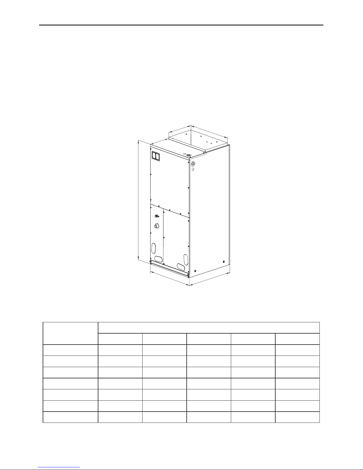
Genex HW(R)130 User manual

Air handler
Air handlers
Installation Manual
Thank you for choosing Air handlers, please read this Installation manual carefully before
operation and retain it for future reference.
GENEX reserves the right to interpret this manual which will be subject to any change due
to product improvement without further notice.
GENEX reserves the nal right to interpret this manual.


Contents
1. Safety Precautions .........................................................................................1
2. Product Introduction .......................................................................................2
2.1 Product Description ....................................................................................2
2.2 Physical Dimension ...................................................................................2
2.3 Names of Main Parts..................................................................................3
2.4 General Information....................................................................................3
3. Preparative for Installation..............................................................................5
3.1 Pre-Installation Instruction .........................................................................5
3.2 Important Safety Instructions .....................................................................5
4. Installation ......................................................................................................7
4.1 Unit Inspection ...........................................................................................7
4.2 Location......................................................................................................7
4.3 Piping Work ................................................................................................8
4.4 Special Instructions ....................................................................................9
4.5 Drain Pan Ret ......................................................................................... 11
4.6 Condensate Removal...............................................................................12
4.7 Ductwork .................................................................................................12
4.8 Electric Heater..........................................................................................12
4.9 Electrical Supply Wire and MOP ..............................................................15
5. Installation Check and Trial Run ..................................................................23
5.1 Checking Items after Installation .............................................................23

5.2 Trial Run ..................................................................................................24
6. Common Malfunction and Elimination..........................................................24
7. Maintenance and Care .................................................................................25
7.1 Outdoor Heat Exchanger..........................................................................25
7.2 Drain Pipe.................................................................................................25
7.3 Notice before Seasonal Use.....................................................................25
7.4 Maintenance after Seasonal Use .............................................................26
7.5 Parts Replacement...................................................................................26
8. After-Sales Service .......................................................................................26

Air Handler
1
1. Safety Precautions
Improper installation, adjustment, alteration, service, maintenance, or use can cause explosion,
fire, electrical shock, or other conditions which may cause death, personal injury, or property
damage. Consult a qualied installer, service agency, or your distributor or branch for information or
assistance. The qualied installer or agency must use factory--authorized kits or accessories when
modifying this product. Refer to the individual instructions packaged with the kits or accessories
when installing. Follow all safety codes. Wear safety glasses, protective clothing, and work
gloves. Use quenching cloth for brazing operations. Have re extinguisher available. Read these
instructions thoroughly and follow all warnings or cautions included in literature and attached to
the unit. Consult local building codes and National Electrical Code (NEC) for special requirements.
Recognize safety information. This is the safety--alert symbol .
When you see this symbol on the unit and in instructions or manuals, be alert to the potential
for personal injury. Understand these signal words; DANGER, WARNING, and CAUTION. These
words are used with the safety--alert symbol. DANGER identies the most serious hazards which
will result in severe personal injury or death. WARNING signifies hazards which could result in
personal injury or death. CAUTION is used to identify unsafe practices which may result in minor
personal injury or product and property damage. NOTE is used to highlight suggestions which will
result in enhanced installation, reliability, or operation.
WARNING
Electrical shock hazard
Failure to follow this warning could result in personal injury or death.
Before installing, modifying, or servicing system,main electrical disconnect switch must be in
the OFF position. There may be more than 1 disconnect switch. Lock out and tag switch with a
suitable warning label.

Air Handler
2
2. Product Introduction
2.1 Product Description
The GENEX HW(R)130 Condensing Unit and HNF Multi-Position Air Handler offer the perfect
combination of superior product quality, operating efciency, operating sound levels and value for
money. The Condensing Unit uses the environmentally friendly refrigerant R410A, which is chlorine-
free to help prevent damage to the ozone layer.
2.2 Physical Dimension
AB
D
W
H
Fig.1
Table 1 Dimension of Indoor Unit
Unit:Inch (mm)
MODEL
DIMENSION
W D H A B
HNF13018/A-D 18-1/8"(460) 21-1/4"(540) 43-1/2"(1105) 11-5/8"(295) 16-3/4"(426)
HNF13024/A-D 18-1/8"(460) 21-1/4"(540) 43-1/2"(1105) 11-5/8"(295) 16-3/4"(426)
HNF13030/A-D 18-1/8"(460) 21-1/4"(540) 43-1/2"(1105) 11-5/8"(295) 16-3/4"(426)
HNF13036/A-D 21-1/4"(540) 21-1/4"(540) 48-1/4"(1224) 11-5/8"(295) 20"(508)
HNF13042/A-D 21-1/4"(540) 21-1/4"(540) 48-1/4"(1224) 11-5/8"(295) 20"(508)
HNF13048/A-D 24-7/8"(630) 21-1/4"(540) 48-1/4"(1224) 11-5/8"(295) 20"(508)
HNF13060/A-D 24-7/8"(630) 21-1/4"(540) 48-1/4"(1224) 11-5/8"(295) 20"(508)

Air Handler
3
2.3 Names of Main Parts
Electric Box Assay
Centrifugal Fan
Fan Motor
Secondary Drain Pan
Evaporator Assy
Primary Drain Pan
Fig. 2
2.4 General Information
Table 2
Model No. Cooling Capacity SCFM Electric Heater (kw)
HNF13018/A-D 1.5 Ton 640 0-10
HNF13024/A-D 2.0 Ton 825 0-10
HNF13030/A-D 2.5 Ton 980 0-15
HNF13036/A-D 3.0 Ton 1140 0-20
HNF13042/A-D 3.5 Ton 1300 0-20
HNF13048/A-D 4.0 Ton 1400 0-20
HNF13060/A-D 5.0 Ton 1650 0-20

Air Handler
4
Table 3
Filters
Model No. Filter size (inch / mm)
HNF13018/A-D 16"×20"×5/8"/406×508×15
HNF13024/A-D 16"×20"×5/8"/406×508 ×15
HNF13030/A-D 16"×20"×5/8"/406×508×15
HNF13036/A-D 19-5/16"×20-5/16"× 5/8"/490×516×15
HNF13042/A-D 19-5/16"×20-5/16"×5/8"/490×516×15
HNF13048/A-D 23"×20-5/16"× 5/8"/585×516×15
HNF13060/A-D 23"×20-5/16"×5/8"/585×516×15
Table 4
Model No. Net Wt / Gross
Wt(kg)
Net Wt / Gross Wt
(lb)
HNF13018/A-D 52 / 56.5 114.7 / 124.6
HNF13024/A-D 53 / 57 116.9 / 125.7
HNF13030/A-D 55.5 / 59 122.4 / 130.1
HNF13036/A-D 65/ 70 143.3 / 154.4
HNF13042/A-D 67/72 147.7 / 158.8
HNF13048/A-D 79 / 84 174.2 / 185.2
HNF13060/A-D 80/86 176.4 / 189.6
Table 5
Model
Airow
Tonnage
Range
Motor @ 230V 1Ph 60Hz DD Blower Wheel
(inch)
Diameter-Width
SCFM vs.ESP(1)(2)
HP FLA 0.1 0.2 0.3 0.4 0.5
HNF13018/A-D 1.5 1/16 0.62 10-8 640 590 510 430 280
HNF13024/A-D 2.0 1/5 1.52 10-8 825 748 668 519 304
HNF13030/A-D 2.5 1/4 1.25 10-8 1000 950 820 730 670
HNF13036/A-D 3.0 1/3 2.0 10-10 1150 1120 1060 990 880
HNF13042/A-D 3.5 1/3 2.0 10-10 1384 1300 1256 1205 1168
HNF13048/A-D 4.0 1/2 2.5 10-10 1510 1400 1350 1325 1265
HNF13060/A-D 5.0 3/4 4.6 11-11 1720 1650 1570 1510 1420
Notes:
① Based upon W/nominal tonnage, dry coil and lter should be installed.
② Use 0.96 as approximate SCFM correction factor for wet coil.

Air Handler
5
3. Preparative for Installation
3.1 Pre-Installation Instruction
3.1.1 Checking Product Received
After receiving the product, please check if there is any damage caused by transportation.
Shipping damage is the responsibility of the carrier. Verify the model number, specications and
accessories are correct prior to installation. The distributor or manufacturer will not accept claims
from dealers for transportation damage or installation of incorrectly shipped units.
3.1.2 Before Installation
Carefully read all instructions for the installation prior to installing product. Make sure each step
or procedure is understood and any special considerations are taken into account before starting
installation. Assemble all tools, hardware and supplies needed to complete the installation. Some
items may need to be purchased locally. Make sure everything needed to install the product is on
hand before starting.
3.1.3 Codes & Regulations
This product is designed and manufactured to comply with national codes. It is installer’s
responsibilities to install the product in accordance with such codes and/or any prevailing local
codes/regulations. The manufacturer assumes no responsibilities for equipment installed in violation
of any codes or regulations.
3.1.4 Replacement Parts
When reporting shortages or damages, or ordering repair parts, give the complete product
model and serial numbers as stamped on the product. Replacement parts for this product are
available through your contractor or local distributor.
3.2 Important Safety Instructions
Recognize Safety Symbols, Words, and Labels
The following symbols and labels are used throughout this manual to indicate immediate or
potential hazards. It is the owner’s responsibility to read and comply with all safety information and
instructions accompanying these symbols. Failure to heed safety information increases the risk of
serious personal injury or death, property damage and/or product damage.
DANGER: Immediate hazards which will result in property damage, product damage, severe
personal injury or death.
WARNING: Hazards or unsafe pratices could result in property damage, product damage,
severe personal injury or death.
CAUTION: Hazards or unsafe practices which may result in property damage, product
damage, severe personal injury or death.
WARNING: Before serving or installing this equipment. The electrical power to this unit
must be in the “off ” position. Caution, more than one disconnect may exist. Failure to observe this
warning may result in an electrical shock that can cause personal injury or death.
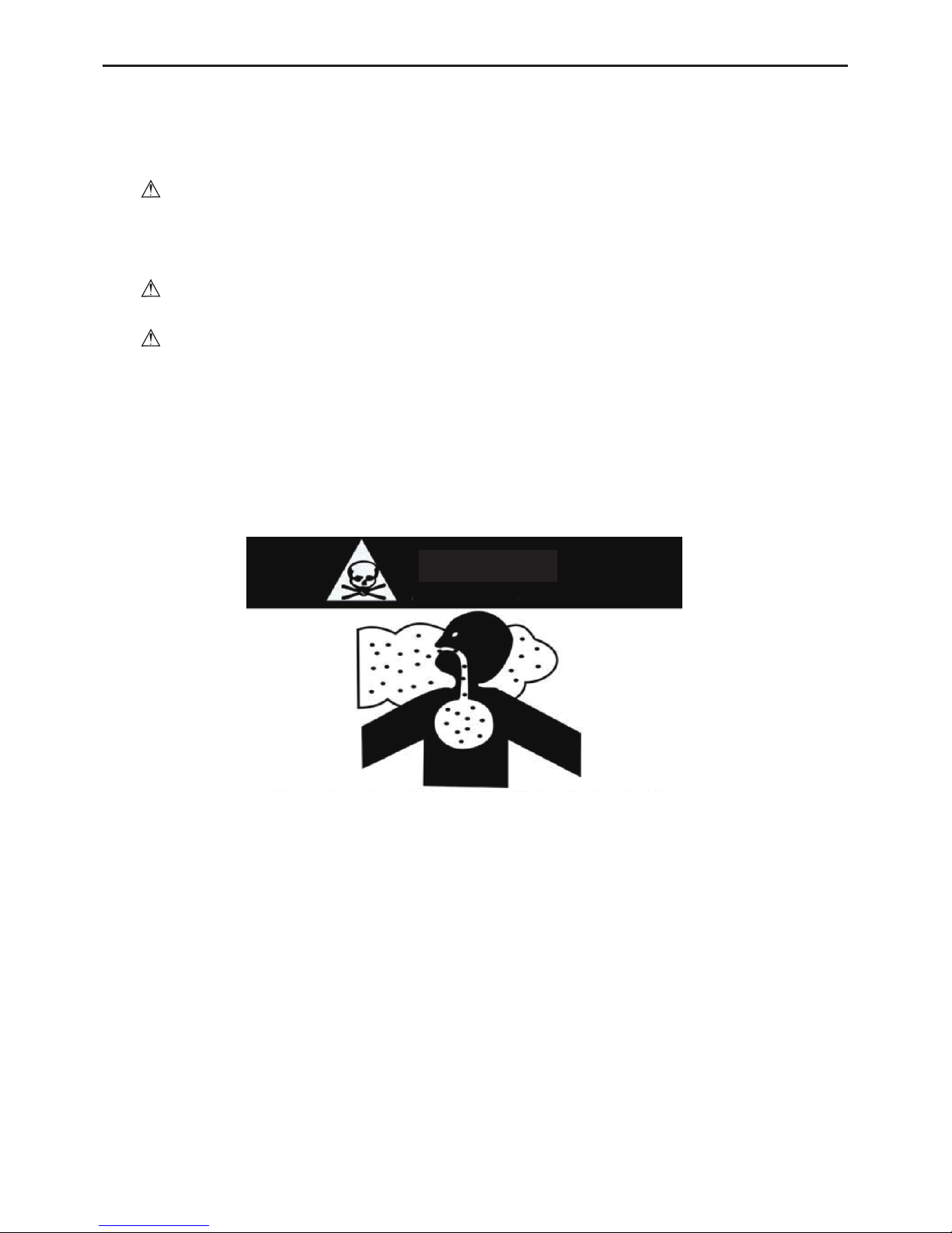
WARNING: The united states environmental protection agency (‘epa”) has issued various
regulations regarding the introduction and disposal of refrigerants introduced into this unit. Failure

Air Handler
6
to follow these regulations may harm the enviroment and can lead to the imposition of substantial
nes. These regulations may vary due to the passage of laws. A certied technician must perform
the installation and service of this product. Should questions arise, contact your local epa ofce.
WARNING: Due to high system pressure and electrical shock in potential, installation and
service work can be dangerous. Only trained and qualied personnels are permitted to install or
service this equipment. Observe all warnings contained in this manual and labels/tags attached to
the equipment.
WARNING: This product is factory shipped for use with a 208-230/1/60 electrical power
supply. This air handler must not be recongured to operate with any other power supply.
WARNING: The unit must have an uninterrupted, unbroken electric grounding to minimize
the possibility of personal injury if an electric fault occurs. The electric grounding circuit may consist
of an appropriate sized power cord which connected with the grounding piece located in the unit
control box and also connecting to the building electric service panel. Other methods of grounding
are permitted if performed in accordance with the “national electric code” (nec)/ “american national
standards institute” (ansi)/ “national re protection association” (nfpa) 70 and local/state codes. In
canada, electric grouding conforms to the canadian electric code csa c22.1. failure to observe this
warning can result in electrical shock that can cause personal injury.
CARBON MONOXIDE POISONING HAZARD
DANGER
Special warning for installation of furnaces or air handling units in enclosed areas, such
as garages, utility rooms or parking areas.
Carbon monoxide producing devices (such as an automobile, space heater, gas water heater,
etc.) should not be operated in enclosed areas such as unventilated garages, utility rooms or
parking areas because of the danger of carbon monoxide (CO) poisoning resulting from the
exhaust emissions.If a furnace or air handler is installed in an enclosed area such as a garge, utility
room or parking area and a carbon monoxide producing device is operated therein, there must be
adequate ventilation directly to outside.
This ventilation is necessary to avoid the danger of CO poisoning which can occur if a carbon
monoxide producing device continues to operate in the enclosed area. Carbon monoxide emission
can be (re)circulated throughout the building if the furnace or air handler is operating in any mode.
CO can cause serious illness including permanent brain damage or death.

Air Handler
7
4. Installation
4.1 Unit Inspection
Upon delivery, inspect the unit for damage. Any damage must be reported immediately to the
carrier. Do not install such an equipment damaged by freight which determines the integrity and
safety of the unit.
Please check the equipment model number to ensure the unit is appropriately sized for the
condensing unit.
If an incorrect unit is supplied, it must not be installed and it is to be returned to the supplier.
The manufacturer assumes no responsibility for the installation of incorrectly delivered units. The
evaporator coil contains high-pressure inert gas for holding charge.
4.2 Location
WARNING: This air handler is designed for indoor installation only. Do not install it outdoors.
When installing the air handler, take consideration to minimize the length of refrigerant tubing as
much as possible. Do not install the air handler in a location either above or below the condenser
that violates the instructions provided with the condenser. Service clearance is to take precedence.
Allow a minimum of 24” in front of the unit for service clearance. When installing in an area directly
over a nished ceiling (such as an attic), an emergency drain pan is required directly under the unit.
See local and state codes for requirements. When installing this unit in an area that may become
wet, elevate the unit with a sturdy, non-porous material. In installations that may lead to physical
damage (i.e. a garage) it is advised to install a protective barrier to prevent such damage.
Fig. 3

Air Handler
8
4.3 Piping Work
4.3.1 Specication of Connection Pipe
Table 6
Model
External Diameter (inch)
Gas Pipe(in) Liquid Pipe(in)
HNF13018/A-D 5/8 3/8
HNF13024/A-D 5/8 3/8
HNF13030/A-D 3/4 3/8
HNF13036/A-D 3/4 3/8
HNF13042/A-D 7/8 3/8
HNF13048/A-D 7/8 3/8
HNF13060/A-D 1 1/8 1/2
4.3.2 Piping Preparation
All cut ends are to be round, burr free, and cleaned. Failure to follow this practice increases the
chances for refrigerant leakage.
Piping Size
For the correct piping size, follow the specication for the condenser/heat pump.
Line set size matches service
valve connection Do not crimp service valve connector
when pipe is smaller than connector
Fig. 4

Air Handler
9
4.3.3 Pipe Connection
This air handler comes with a plastic accessory bag which contains: piston, tailpiece and white
teon seal. Please refer to table7 to verify the piston size before installation.
Table 7 PISTON KIT CHART
OUTDOOR UNIT INDOOR UNIT INDOORS PISTON SIZE(inch) PISTON KIT PART NO.
HW13018Na/A-D HNF13018/A-D ¢0.053 053
HW13024Na/A-D HNF13024/A-D ¢0.054 054
HW13030Na/A-D HNF13030/A-D ¢0.064 064
HW13036Na/A-D HNF13036/A-D ¢0.067 067
HW13042Na/A-D HNF13042/A-D ¢0.071 071
HW13048Na/A-D HNF13048/A-D ¢0.079 079
HW13060Na/A-D HNF13060/A-D ¢0.084 084
HWR13018Na/A-D HNF13018/A-D ¢0.055 055
HWR13024Na/A-D HNF13024/A-D ¢0.057 057
HWR13030Na/A-D HNF13030/A-D ¢0.068 068
HWR13036Na/A-D HNF13036/A-D ¢0.067 067
HWR13042Na/A-D HNF13042/A-D ¢0.073 073
HWR13048Na/A-D HNF13048/A-D ¢0.082 082
HWR13060Na/A-D HNF13060/A-D ¢0.091 091
4.4 Special Instructions
This air handler comes with a plastic accessory bag which contains: tailpiece and white teon
seal.
WARNING: The coil is shipped under pressure. Release the pressure before installation.
Evaporator Coil Metering Devices
(1) Remove 9/16 nut, then press the Schneider valve to release pressure, no gas indicates a
possible leak.
(2) After the gas has released, remove the 13/16 nut, Schneider valve and white teon seal
from the liquid line distributor.
(3) Take the piston from the plastic accessory bag and then Insert the piston into the liquid line
distributor.
(4) Take the tailpiece from the plastic accessory bag and slide the 13/16 nut into place.
(5) Braze tailpiece to the line set liquid tube.
(6) Braze suction line. Remove cap closure from suction line .
(7) Insert the suction line into the connection, slide the rubber grommet at least 18" away from
the braze joint.
(8) After the tailpiece has been cooled, conrm the position of white teon seal and tighten the
13/16 nut manually.
(9) Torque the 13/16nut to 20-30 ft-lbs.

Air Handler
10
(10) Replace suction line grommet.
13/16" NUT
9/16" NUT
Schneider valve and
white teon seal
Fig. 5
Flowrator
Piston
13/16" NUT
Tailpiece
White teon seal
Fig. 6
Cap closure
Rubber grommet
Suction line
Fig. 7
Note: The tightening torque of the 13/16 screw nut shall not be more than 30N·m.

Air Handler
11
4.5 Drain Pan Ret
Based upon the actual conditions, if the unit is installed as per Fig.3, there is no need to adjust
the drain pan; otherwise, the auxiliary drain pan is required to be retted on the opposite side.
The following instruction shows how to ret the auxiliary drain pan from left to right side of the
unit. As the auxiliary drain pan is universally used on both sides, only change the position of plastic
drain pan cap for replacement.
As shown in Figure 8, it is recommended that the drain pan should be ret before installation
and locate the air handler in an area that allows for access to all sides.
(1) Disassemble the front panel.
(2) Remove the mounting plate used to fix the drain pan from chassis. And dismantle the
enhanced frame, if applicable.
(3) Pull out the evaporator coil and the drain pan in horizontal.
(4) Reset the drain pan in vertical at the right side of the evaporator coil. Note: Push the
evaporator coil backwards and make sure that there is no gap between the drain pan and the xed
bracket.
(5) Fix the evaporator by enhanced frame (if applicable) and reset the mounting plate by
tightening the screws.
(6) Reassemble the front panel as per the reverse disassembly order mentioned above.
A)Factory configuration:
Auxiliary drain pan on the left
B)Replacement configuration:
Auxiliary drain pan on the right
Enhanced frame
Main drain pan
Mounting plate
Auxiliary drain pan
Rainspout
Rainspout
Auxiliary drain pan
Fig. 8

Air Handler
12
4.6 Condensate Removal
The drain pan has primary and secondary drain connection (Figure 8). Condensate removal is
performed by attaching a 3/4” PVC pipe to the evaporator coil pan and terminated in accordance
with local or state Plumbing/HVAC codes. The installation must include a “P” style trap that is
located closely to the evaporator coil. Do not over-tighten the drain connection(s) in order to
prevent possible damage to the evaporator drain pan.
See Figure 9 for details of a typical condensate line “P” trap.
Unit
Drain connection
Flexible tubing
(hose or pipe)
Positive liquid
seal (REQ'D)
2" minimum
3" minimum
Fig. 9
4.7 Ductwork
This air handler is designed for a complete supply and return ductwork
system.
WARNING: Do not operate the unit without all ductwork completed.
To ensure correct system performance, the ductwork is to be sized to accommodate Table 5.
Inadequate ductwork that restricts airow may result in improper performance and compressor or
heater failure. Ductwork is designed with less restrictions of airow and maintains suitable airow
speed. And keep the ductwork sealed with good hermeticity.
Return Ductwork. Do not place the duct inlet at a place where is lled with toxic gas or harmful
fume/odor. For upow conguration, duct terminal connects to the bottom of the air handler.
Return Air Filters. Each installation must include a return air filter. This filtering may be
performed at the air handler or externally such as a return air lter grille.
4.8 Electric Heater
The air handlers listed in this manual do not have factory installed electric heat. Electric heat is
available as an accessory. The only heater kits that can be used are HNRd series. Please refer to
installation instructions provided with heater kit for the correct installation procedure.
WARNING: Refer to the “installing electric heater” section of this manual and the instructions
provided with the heater kit for the correct installation procedure.
WARNING: The electrical characteristics of the air handler, the electric heater kit, and the
supply power should be identical. This air handler does not have factory installed electric heater.
Electric heater is available as an accessory. If installing this optition, the only heater kits that can be
used are the HNRD series as indicated below.

Air Handler
13
The heating mode temperature rise is dependent upon the system airow, the supply voltage,
and the heater kit size (KW) selected. Use Tables 8-10 to determine the temperature rise(ºF).
N/ATable 8
CFM HEATER KIT NOMINAL KW
5 10 15 20
600 28 56 N/A N/A
800 21 42 N/A N/A
1000 17 34 50 N/A
1200 14 28 42 56
1400 12 24 36 48
1600 10 21 31 42
1800 9 19 28 37
230/1/60 Supply Voltage-Temperature Rise Table ºF
Table 9
CFM HEATER KIT NOMINAL KW
5 10 15 20
600 27 52 N/A N/A
800 20 40 N/A N/A
1000 16 32 48 N/A
1200 13 27 40 53
1400 11 23 34 46
1600 10 20 30 40
1800 9 18 27 36
220/1/60 Supply Voltage-Temperature Rise Table ºF
Table 10
CFM HEATER KIT NOMINAL KW
5 10 15 20
600 25 50 N/A N/A
800 19 38 N/A N/A
1000 15 30 46 N/A
1200 13 25 38 56
1400 11 22 33 48
1600 9 19 28 42
1800 8 17 25 37
208/1/60 Supply Voltage-Temperature Rise Table ºF.
Note: For installations not indicated above the following formula is to be used:
TR= (kW*3412)*(Voltage Correction)*1.08/CFM
Where: TR=Temperature Rise
KW=Heater Kit Actual kW
3412=Btu per kW
Voltage Correction= 0.96(230 Supply Volts)
0.92(220 Supply Volts)
0.87(208 Supply Volts)
1.08=Constant CFM=Measured Airow

Air Handler
14
Note: The Temperature Rise Tables can also be used to determine the air handler airflow
delivery. When using these tables for this purpose, set the room thermostat to maximum heat and
allow the system to reach steady state conditions. Set two thermometers, one in the return air inlet
and the other one in the supply air outlet.
4.8.1 “HNRd” Electric Heater Kits Available
Table 11
SN. Kit# Description Ref. Air Handler use
1 HNRd5-D Circuit Breaker, 5kw Heat Strip 18,24,30,36,42,48,60
2 HNRd10-D Circuit Breaker, 10kw Heat Strip 18,24,30,36,42,48,60
3 HNRd15-D Circuit Breaker, 15kw Heat Strip 30,36,42,48,60
4 HNRd20-D Circuit Breaker, 20kw Heat Strip 36,42,48,60
4.8.2 “HNRd” Heater Kits Installation
CAUTIONS:
(1) Ensure that all power supply is disconnected prior to installing the heater kit.
(2) A means of strain relief and conductor protection must be provided at the supply wire
entrance into cabinet.
(3) Use copper conductors only.
(4) Installation must follow national electric code and other applicable codes.
(5) If this appliance is installed in an enclosed area such as a garage or utility room with any
carbon monoxide producing appliance, ensure the area is properly ventilated.
1) Refer to Table 11 for appropriate HNRd heater kit.
2) Check any physical damage, do not install damaged heater kit.
3) Remove the upper access panel from air handler.
4) Remove cover plate from air handler.
5) Slide the heater kit in to the slot and secure element plate with previously removed screws.
6) Insert power leads into the circuit breaker lugs or stripped red and black wires (For heater
kit without circuit breaker) and tighten.
7) Connect ground wire to ground lug.
8) Break out appropriate area of the plastic circuit breaker cover on the access panel of the
air handler.
9) Replace access panel and check operation.
Heater kit
Cover plate
Bolt Circuit breaker

Air Handler
15
4.9 Electrical Supply Wire and MOP
WARNING: More than one disconnect may exist. Failure to observe this warning may result
in an electrical shock that can cause personal injury or death.
WARNING: To avoid the risk of the re or equipment damage, only use copper conductors.
Before servicing or installing this equipment, the electrical power to this unit must be in “off” position
and all power supplies should be disconnected.
WARNING: The unit must have an uninterrupted, unbroken electric grounding to minimize
the possibility of personal injury if an electric fault occurs.The electric grounding circuit may consist
of an appropriate sized power cord which connected with the grounding piece located in the unit
control box and also connecting to the building electric service panel. Other methods of grounding
are permitted if performed in accordance with the “national electric code” (nec)/ “american national
standards institute” (ansi)/ “national re protection association” (nfpa) 70 and local/state codes. In
canada, electric grouding conforms to the canadian electric code csa c22.1. failure to observe this
warning can result in electrical shock that can cause personal injury.
4.9.1 Inspection of the Building Electrical Service
This product is designed for single-phase electrical supply. DO NOT OPERATE ON A THREE-
PHASE POWER SUPPLY. Measure the power supply to the unit. The supply voltage must be in
agreement with the unit nameplate power requirements and within the range shown in Table 12.
Table 12
Nominal Input Minimum Voltage Maximum Voltage
208/230 187 254

Air Handler
16
4.9.2 Wire Sizing
Wire size is important to the operation of your equipment. Use the following check list when
selecting the appropriate wire size for your unit.
Wire size must carry the Minimum Circuit Ampacity (MCA).
Table 13
Model Nominal
CFM
Nominal
Capacity
BTU/H
Blower
Motor Full
Load Amps
Electric Heat
(kw)
Min. Circuit
Ampacity*
Max. Fuse or
Breaker(HACR)
Ampacity
240V 208V 240V 208V 240V 208V
HNF13018/
A-D 640 18000 0.62
0 0 0.65 0.65 15 15
5 3.8 26.8 23.3 30 25
10 7.5 52.9 45.9 60 50
HNF13024/
A-D 825 24000 1.52
0 0 1.9 1.9 15 15
5 3.8 26.9 23.4 30 25
10 7.5 52.9 45.9 60 50
HNF13030/
A-D 980 30000 1.25
0 0 1.7 1.7 15 15
5 3.8 27.6 24.1 30 25
10 7.5 53.6 46.7 60 50
15 11.3 53.6/26 46.7/23 60/30 50/25
HNF13036/
A-D 1140 36000 2
0 0 2.5 2.5 15 15
5 3.8 28 24.4 30 25
10 7.5 54 47 60 50
15 11.3 54/26 47/22.5 60/30 50/25
20 15 54/52.1 47/45.1 60/60 50/50
HNF13042/
A-D 1350 42000 2
0 0 2.5 2.5 15 15
5 3.8 28.1 24.6 30 25
10 7.5 54.2 47.1 60 50
15 11.3 54.2/26 47.1/22.5 60/30 50/25
20 15 54.2/52.1 47.1/45.1 60/60 50/50
HNF13048/
A-D 1400 48000 2.5
0 0 3.1 3.1 15 15
5 3.8 29.3 25.8 30 30
10 7.5 55.3 48.3 60 50
15 11.3 55.3/26 48.3/22.5 60/30 50/25
20 15 55.3/52.1 48.3/45.1 60/60 50/50
HNF13060/
A-D 1650 60000 4.6
0 0 5.8 5.8 15 15
5 3.8 31.8 28.6 35 30
10 7.5 57.8 50.8 60 60
15 11.3 57.8/26 50.8/22.5 60/30 60/25
20 15 57.8/52.1 50.8/45.1 60/60 60/50
Table of contents
Popular Air Handler manuals by other brands

System air
System air SAVE CONNECT user manual

Airmax
Airmax MaxAir 50eP2 Design, Installation and Maintenance Instructions

System air
System air Topvex 1000 R Operating and maintenance instructions

Water Furnace
Water Furnace TruClimate 500 installation guide

System air
System air SAVE VSR 150/B user manual

System air
System air VR-250 EH/B /3 User and maintenance instructions

WEGER WALTER GMBH
WEGER WALTER GMBH DIWER EVO Series Installation and operating manual

Wolf
Wolf KG Standard Installation and maintenance instructions

Pioneer
Pioneer WYS Series Disassembly guide

Vivax
Vivax RG10N2 (D2S) manual

Trox Technik
Trox Technik FK2-EU Additional manual

Trane Technologies
Trane Technologies THERMO KING UT-1290 installation manual