Genie WRR-2 User manual

Quick Start Guide
Please read these instructions carefully before operating the unit
and keep for further reference.
2 Channel Wiegand Radio
Receiver – Up to 30m
WRR-2

ii
Intro Section
This Quick Start Guide is intended for experienced installing technicians. It is a basic
reference to ensure all connections are properly made. Installation and wiring of systems
must be in accordance with the National Electrical Code, ANSI/NFPA 70.
The contents of this manual are subject to change without notice.

Contents
iii
1.1 Product Features...........................................................................................4
1.2 Product Layout.............................................................................................4
1.3 Specification.................................................................................................4
1.4 Cable Requirements.....................................................................................5
1.5 Output Formats............................................................................................5
1.6 Grounding ....................................................................................................5
1.7 Power............................................................................................................5
1.8 Mounting .....................................................................................................5
1.9 Read Range ..................................................................................................5
1.10 External LED Indicator ................................................................................5
1.11 6-Pin Terminal Block ....................................................................................6
1.12 Connection..................................................................................................6
1.13 Troubleshooting..........................................................................................6

Quick Start Guide 2 Channel Wiegand Radio Receiver - Up to 30m
4
The Genie WRR-2 is a 2 channel long range Wiegand radio receiver that allows interface
with a wide range of electronic access control systems by complying with the Wiegand
communication protocol.
1.1 Product Features
• MAXSecure™ – Unique security feature
• Wiegand output interface
• ETL listed – Independently tested and
• certified to conform to UL Standard 294
• Wall mount box for box or flat surfaces
• Electronics sealed in a weather resistant enclosure (IP65)
1.2 Product Layout
a. 6-PIN Terminal Block
1.3 Specification
Frequency 433MHz
Transmission Rolling code and encryption
IP Rating IP65
Voltage DC12V (Nominal)
Current Draw 80mA typical @ DC12V
Read Range Up to 30m (Installer adjustable)
Cabling 24 AWG minimum, multi-conductor stranded with an overall foil shield
Interface Wiegand (26 Bit industry standard and custom Wiegand formats)
Audio Tone N /A
LED External four-state standard (red, green, amber, and off), Power (blue), and
Channel (green)
Operating Temperature -40°C to +65°C, 5–95% RH (Non-condensing)
Certifications FCC, ICC, CE, UL Standard 294
Dimensions 84 × 84 × 48.3 mm
Weight 227g

Quick Start Guide 2 Channel Wiegand Radio Receiver - Up to 30m
5
1.4 Cable Requirements
24 AWG minimum, multi-conductor stranded with an overall foil shield, for example Belden
9540 or similar. Per the SIA’s Wiegand specification, maximum cable length is 500 feet
(152.4 m).
1.5 Output Formats
Wiegand (industry standard 26-bit Wiegand and custom Wiegand formats).
1.6 Grounding
Shield (drain) continuity must run from the Receiver to the access panel. Further, the shield
and Receiver ground must be tied together at the access panel, and must connect to an
earth ground at one point only.
1.7 Power
Power required is 12 VDC nominal at 80 mA. The Receiver may be powered by the access
panel. A linear power supply is recommended for best operation.
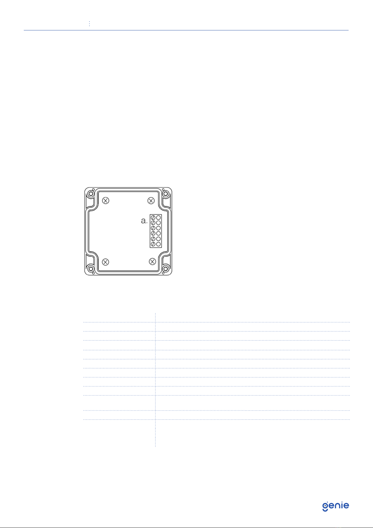
1.8 Mounting
The Receiver may be mounted indoors or outdoors. The enclosure includes pre-drilled
holes in the four corners allowing mounting to a flat surface. Use supplied #6 mounting
screws, or equivalent security screws, for installation.
1.9 Read Range
Read range is nominally up to 100 feet (30.5 m). For optimal read range, it is important
that the Receiver be mounted as far from potential interference sources as possible. These
sources may include, but are not limited to, large metal and concrete obstructions, as
well as magnetic fields and radio transmissions. Further range varies based on the height a
Receiver is installed, how a user may hold a Transmitter when being used, and where the
Transmitter is being used. Read range may vary for each installation.
1.10 External LED Indicator
Refer to the information below for explanation on the Receiver’s external LED indicator
operation:

Quick Start Guide 2 Channel Wiegand Radio Receiver - Up to 30m
6
1.11 6-Pin Terminal Block
Refer to the information below for cabling to the Receiver:
AD0: Button One, Wiegand Data 0, Channel A.
AD1: Button One, Wiegand Data 1, Channel A.
BD0: Button Two, Wiegand Data 0, Channel B.
BD1: Button Two, Wiegand Data 1, Channel B.
GND: Power, 0VDC
+VDC: Power, 12VDC Nominal.
NOTE: Apply positive voltage only to the +VDC Pin on the Terminal Block.
1.12 Connection
Connection must be done in accordance with NFPA 70. Do not connect to a receptacle
controlled by a switch. Connect to a power limited DC voltage source.
1.13 Troubleshooting
No data received/Transmitter not enrolled
Transmitter must be clicked twice to be learned by the Receiver upon initial Receiver
power up
Table of contents
Other Genie Receiver manuals