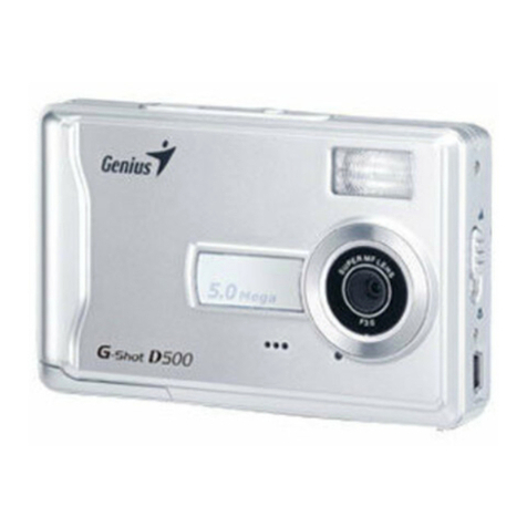
Genius G-Shot P611 User manual
Other Genius Digital Camera manuals
Genius
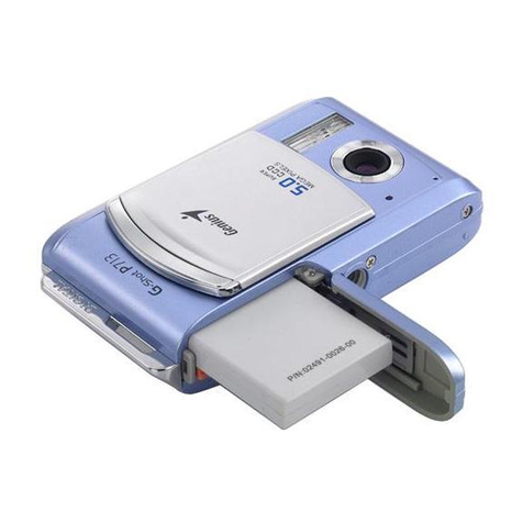
Genius G-SHOT P713 MP3 User manual

Genius
Genius DSC13M SMART User manual

Genius
Genius P633 User manual
Genius
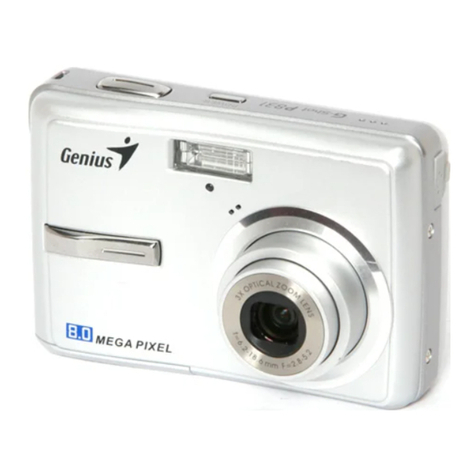
Genius P831 User manual
Genius
Genius DSC-1.3M Smart User manual
Genius
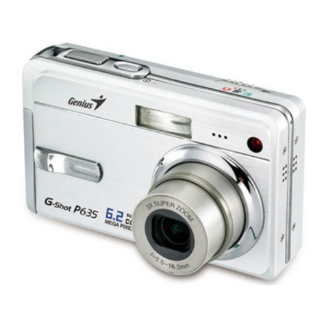
Genius P635 User manual
Genius
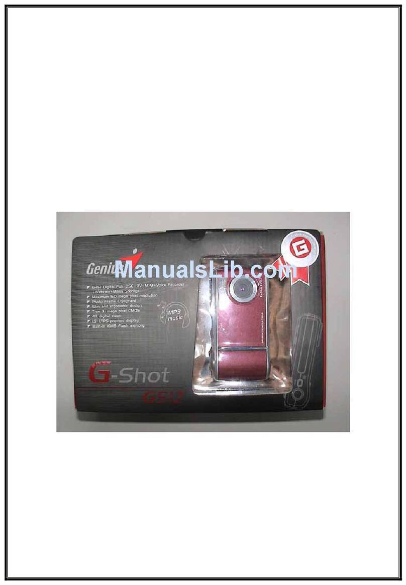
Genius G-Shot G512 User manual
Genius
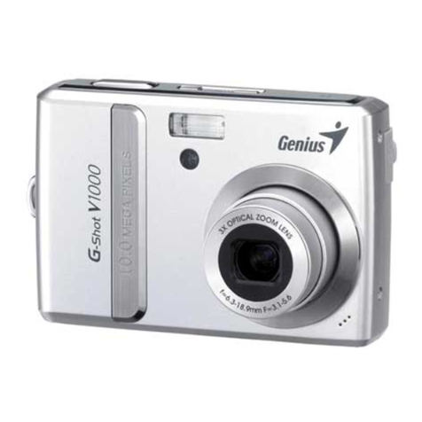
Genius V1000 User manual
Genius
Genius DSC13M SMART User manual
Genius
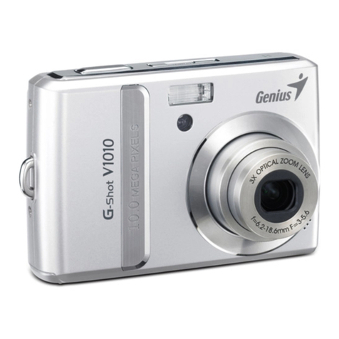
Genius V1010 User manual
Genius
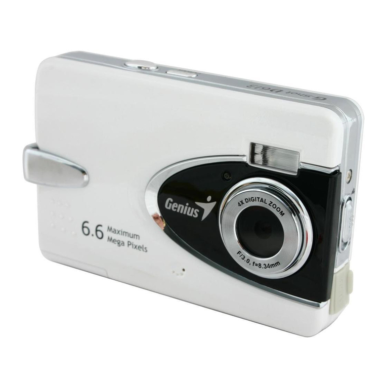
Genius D613 User manual
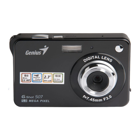
Genius
Genius Digital Camera User manual
Genius
Genius P536 User manual
Genius
Genius P535 User manual
Genius
Genius DSC 13M User manual
Genius
Genius P517 User manual
Genius
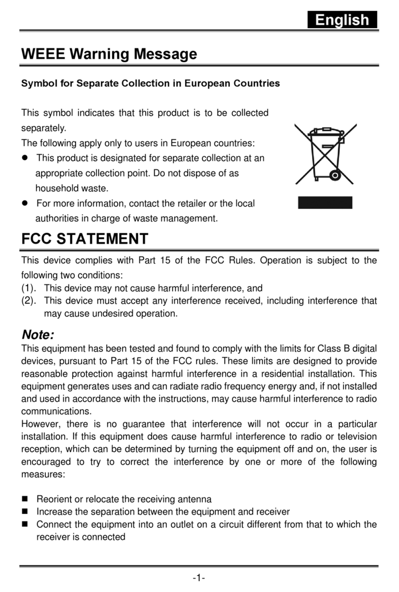
Genius G-Shot G511 User manual
Genius
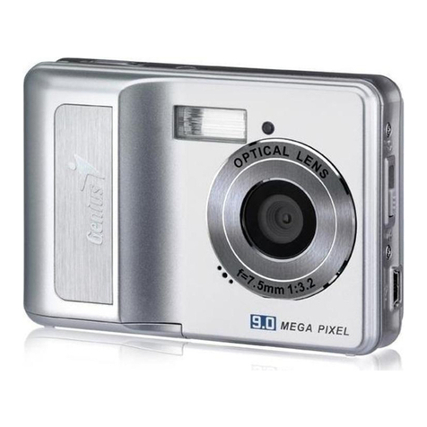
Genius D5175 User manual
Genius
Genius NAVIGATOR 900 User manual
Genius
Genius P8565 User manual

